EP0968945B1 - Dispositif de déroulage - Google Patents
Dispositif de déroulage Download PDFInfo
- Publication number
- EP0968945B1 EP0968945B1 EP99109912A EP99109912A EP0968945B1 EP 0968945 B1 EP0968945 B1 EP 0968945B1 EP 99109912 A EP99109912 A EP 99109912A EP 99109912 A EP99109912 A EP 99109912A EP 0968945 B1 EP0968945 B1 EP 0968945B1
- Authority
- EP
- European Patent Office
- Prior art keywords
- bearing
- bearing supports
- supporting shaft
- unroll
- axis
- Prior art date
- Legal status (The legal status is an assumption and is not a legal conclusion. Google has not performed a legal analysis and makes no representation as to the accuracy of the status listed.)
- Expired - Lifetime
Links
- 238000005096 rolling process Methods 0.000 description 30
- 238000006073 displacement reaction Methods 0.000 description 3
- 239000012530 fluid Substances 0.000 description 3
- 238000004804 winding Methods 0.000 description 2
- 238000002372 labelling Methods 0.000 description 1
- 239000000463 material Substances 0.000 description 1
- 230000001960 triggered effect Effects 0.000 description 1
Images


Classifications
-
- B—PERFORMING OPERATIONS; TRANSPORTING
- B65—CONVEYING; PACKING; STORING; HANDLING THIN OR FILAMENTARY MATERIAL
- B65H—HANDLING THIN OR FILAMENTARY MATERIAL, e.g. SHEETS, WEBS, CABLES
- B65H16/00—Unwinding, paying-out webs
- B65H16/02—Supporting web roll
- B65H16/06—Supporting web roll both-ends type
-
- B—PERFORMING OPERATIONS; TRANSPORTING
- B65—CONVEYING; PACKING; STORING; HANDLING THIN OR FILAMENTARY MATERIAL
- B65H—HANDLING THIN OR FILAMENTARY MATERIAL, e.g. SHEETS, WEBS, CABLES
- B65H19/00—Changing the web roll
- B65H19/10—Changing the web roll in unwinding mechanisms or in connection with unwinding operations
- B65H19/12—Lifting, transporting, or inserting the web roll; Removing empty core
- B65H19/126—Lifting, transporting, or inserting the web roll; Removing empty core with both-ends supporting arrangements
-
- B—PERFORMING OPERATIONS; TRANSPORTING
- B65—CONVEYING; PACKING; STORING; HANDLING THIN OR FILAMENTARY MATERIAL
- B65H—HANDLING THIN OR FILAMENTARY MATERIAL, e.g. SHEETS, WEBS, CABLES
- B65H2511/00—Dimensions; Position; Numbers; Identification; Occurrences
- B65H2511/10—Size; Dimensions
- B65H2511/12—Width
Definitions
- the invention relates to a rolling device according to the preamble of Claim 1.
- Such rolling devices are, for example, from EP 0 629 574 B1 known.
- the paper roll on the support i.e. opposite the floor, so that the Center axis of the roll parallel to the roll axis of the roll device runs.
- a device such as that used in EP 0 700 854 is used, for example A2 (corresponding to U.S. Patent 5,755,395) is shown and described.
- DE 42 24 309 A1 describes a tensioning device for coils or winding cores known for tape material that paired with each other Has coil support arms, the one hand in horizontal in their distance mutually changeable holders are pivotally mounted and on their free ends have receiving pins for receiving a coil.
- the support arms can be pivoted by means of vertical drives in such a way that their The mounting spigot can be adjusted essentially vertically.
- the coil support arms are further adjustable in their distance from each other and overall can be moved horizontally across its roll axis. They continue to point a decentering device, by means of which the receiving pins for a coil at the same time and opposite from its coaxially aligned Position can be moved. To function is overall only indicated that the support arms have greater freedom of movement and more extensive Adjustment options for mutual approaching or removing is awarded, which also means an enlarged work area in relation to the width of the spools or winding rolls.
- a rolling device is also known from DE G 86 29 994 U, in which the support shaft carrying the support arms in a parallel steering system is mounted so that the locating pin is forcibly in one Be guided in the vertical plane.
- the invention has for its object a rolling device Generic type so that an alignment of the to be recorded Do not roll before being picked up by the roll-off device necessary is.
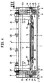
- Each rolling device shown in the drawing has - as FIG. 1 and FIG. 3 can be seen - two mirror-symmetrical to one to the plane of the drawing 2 or 4 parallel vertical center plane 2 arranged Unroll devices 1.1a. Because of the mirror symmetry of this Devices 1, 1a subsequently become those on the left in FIGS. 1 and 3, respectively Parts associated with the illustrated device 1 with a simple reference number and that of the device 1a shown in FIGS. 1 and 3 on the right assigned parts with the same reference number with the addition of a "a" denotes, without the need for a double description. As can also be seen in FIGS. 2 and 4, the two rolling devices are 1 and 1a each again largely mirror-symmetrical to a vertical running parallel to the drawing plane of FIGS.
- the rolling device has a machine frame 4, the two at a distance bearing stands 5, 5 'arranged from one another, which by means of an upper longitudinal beam 6 and lower longitudinal struts 7, 7a stiff with each other are connected.
- the stands 5, 5 ' are by means of base plates 8, 8' Ground foundations 9, 9 'supported.
- 10a, 10 ' engages as a sliding drive a swivel drive 12, 12a, as a piston-cylinder drive which can be acted upon with pressure fluid on both sides trained and stationary, but swiveling in one the respective base plate 8, 8 'attached base bearing 13, 13a is.
- Support shaft 14, 14a supported at both ends, with bearings 15, 15 'or 15a.
- These bearings 15, 15 'and 15a are designed so that the Support shafts 14, 14a can not only be moved so that their central longitudinal axes 16, 16a parallel to themselves and to the vertical median plane 2 are moved, but that they are also opposite to their longitudinal direction can be pivoted or deflected. So you can be so distracted be that their central longitudinal axes 16,16a substantially in the Horizontal moved out of a position parallel to the vertical center plane 2 become.
- the bearings 15, 15 'and 15a are, for example, as spherical bearings designed with a certain pivoting mobility and with a certain displacement in the direction of the respective Axis 16 and 16a are mounted in the bearing levers 10, 10 'and 10a.
- the Bearings 15, 15 'and 15a are located on the base bearings 11, 11a and 11 'opposite upper ends of the bearing levers 10, 10a and 10'.
- each support shaft 14, 14a there are two support arms at a distance from one another 17, 17 'and 17a attached to the support shaft 14, 14a rotatably.
- support shafts 14, 14a each point parallel to their central longitudinal axis 16, 16a extending outer guide grooves 18 into which the respective Support arms 17, 17 ', 17a engage trained projections 19, 19a, so that the support arms 17, 17a, 17 'relative to the respective support shaft 14, 14a rotatably but slidably mounted in the longitudinal direction thereof are.
- Support arms 17, 17 'and 17a are mounting pins 24, 24' attached are directed towards each other in each rolling device 1 or 1a.
- the swivel drives 12 and 12a of each rolling device 1 and 1a are can be acted upon independently, that is to say can be controlled, so that the triggered movements are independent of each other.
- the pivot arms 21, 21 ' are pivoted by means of the lifting drives 22, 22' in such a way that that the receiving pin 24, 24 'in a to the central axis 29 of the Roll 28 aligned position come. If the rolling axis 26 is not parallel to the central axis 29, ie not parallel to the vertical central plane 2, runs, then by correspondingly different control the pivot drives 12, the bearing levers 10, 10 'pivoted so that the Roll axis 26 in a position parallel to the central axis 29 of the paper roll 28 is coming.
- each rolling device 1 and 1a pivoted relative to each other can be, with appropriate pivoting the corresponding central longitudinal axis 16 or 16a of the respective support shaft 14 or 14a and thus the rolling axis 26 or 26a.
- the bearing lever 10, 10 'and 10a can different non-parallel courses of the central axis 29 of the Roll 28 are balanced relative to the median level 2, as in the for the Unrolling device 1 indicated in Fig. 1 swivel tracks 30 and 31st for the central axis of the roller 28 is shown.
- the setting drives 20 are controlled in such a way that the receiving pin 24, 24 'concentrically in the paper roll 28 intervene. Then, by appropriate control, the Swivel drives 12, 12 'an alignment of the paper roll 28 in such a way that its central axis 29 in a parallel to the central plane 2 and horizontal position, i.e. the desired starting position. Subsequently it is applied to the lifting drives 22, 22 'in a Unroll suitable position swiveled up.
- each support shaft 14, 14a in principle only one lifting drive 22 or 22a or 22 'or 22a' is necessary; it is only for each support shaft 14, 14a in the illustrated Embodiments provided two lifting drives 22, 22 'and 22a, 22a', around no significant torsions in the respective support shaft 14 or 14a let develop.
- Fig. 2 the greatest possible length a is one for the rolling device 1 paper roll 28 to be accommodated and the smallest possible length b a Paper roll 28 shown. 1 is left for the swivel path 30 with the support shaft shifted as far as possible towards the central plane 2 14 the entire pivoting range of the support arms 17, 17 'indicated while in Fig. 1 on the right for the rolling device 1a for the swivel track 31a as far as possible from the center plane 2 pivoted support shaft 14a the largest possible swivel range of the support arms 17a is shown.
- the control of the various drives that can be pressurized with fluid, thus the swivel drives 12 and 12a, the shift drives 20, 20a and the lifting drives 22, 22 ', 22a, 22a' takes place in a known manner, for example via solenoid valves, which in turn are only indicated central controller 33 are controlled.
- This central controller 33 receives signals from only indicated sensors 32, 32 ', 32a, the actual position the paper roll 28, specifically its distance from the donors and thus from the vertical center plane 2.
- the paper roll 28 donors 34 and 34a are provided, the distance the paper roll 28 from the respective upper encoder 34 or 34a and thus capture the distance 29 over the pad 27. Of these donors 34, or 34a, the diameter of the roller 28 is detected.
- the encoders 32, 32 'and 32a In contrast, with the encoders 32, 32 'and 32a, the skew of the axis 29 relative to the vertical center plane 2. Such an imbalance can, for example up to +/- 60 mm, which can be compensated. Furthermore can be activated via a suitable control of the part-turn actuators 12 or 12a uneven web tension can be compensated.
Landscapes
- Replacement Of Web Rolls (AREA)
- Spinning Or Twisting Of Yarns (AREA)
Claims (7)
- Dispositif de déroulage pour rouleaux de papier (28), équipé d'au moins un mécanisme dérouleur (1, 1a) comprenantcaractérisé par le fait que l'arbre de support (14, 14a) est monté, dans les supports stabilisateurs (10, 10', 10a ; 35, 35', 35a), de façon telle que son axe médian longitudinal (16, 16a) puisse non seulement coulisser parallèlement à lui-même, mais puisse également pivoter autour d'une position initiale, pour l'essentiel selon une horizontale ; et par le fait que les entraínements en translation (12, 12' ; 37, 37a) peuvent être actionnés indépendamment les uns des autres.un bâti de machine (4), muni de deux montants de portée (5, 5') distants l'un de l'autre,des supports stabilisateurs (10, 10', 10a ; 35, 35', 35a), sensiblement guidés avec mobilité horizontale sur lesdits montants de portée (5, 5'),des entraínements en translation (12, 12a ; 37, 37a) venant en prise avec les supports stabilisateurs (10, 10', 10a ; 35, 35', 35a),un arbre de support (14, 14a), monté dans les supports stabilisateurs (10, 10', 10a ; 35, 35', 35a) par ses extrémités,des bras de support (17, 17', 17a) guidés sur l'arbre de support (14, 14a) avec verrouillage rotatif par rapport à ce dernier, mais avec faculté de coulissement dans leur direction longitudinale,des pointeaux récepteurs (24, 24', 24a) destinés à recevoir un rouleau (28), implantés sur les bras de support (17, 17', 17a) et définissant un axe de dévidage (26, 26a), etau moins un entraínement de levage (22, 22', 22a, 22'a) couplé à l'arbre de support (14, 14a),
- Dispositif de déroulage selon la revendication 1, caractérisé par le fait que l'arbre de support (14, 14a) est monté sur les supports stabilisateurs (10, 10', 10a ; 35, 35', 35a) au moyen de paliers sphériques (15, 15', 15a).
- Dispositif de déroulage selon la revendication 1 ou 2, caractérisé par le fait qu'un jeu est réservé entre l'arbre de support (14, 14a) et les supports stabilisateurs (10, 10', 10a ; 35, 35', 35a), dans la direction de l'axe médian longitudinal (16, 16a) dudit arbre de support (14, 14a).
- Dispositif de déroulage selon l'une des revendications 1 à 3, caractérisé par le fait que les supports stabilisateurs sont réalisés sous la forme de leviers de portée (10, 10', 10a) articulés, sur les montants de portée (5, 5'), avec faculté de pivotement.
- Dispositif de déroulage selon l'une des revendications 1 à 3, caractérisé par le fait que les supports stabilisateurs (35, 35', 35a) sont réalisés avec faculté de coulissement sensiblement horizontal sur le montant de portée (5, 5').
- Dispositif de déroulage selon l'une des revendications 1 à 5, caractérisé par la présence d'au moins un capteur (34, 34a), afin de détecter la distance comprise entre ledit capteur (34, 34a) et un axe médian longitudinal (29) du rouleau (28).
- Dispositif de déroulage selon l'une des revendications 1 à 6, caractérisé par la présence de capteurs (32, 32', 32a) conçus pour détecter une position oblique du rouleau (28).
Applications Claiming Priority (2)
| Application Number | Priority Date | Filing Date | Title |
|---|---|---|---|
| DE19824695A DE19824695A1 (de) | 1998-06-03 | 1998-06-03 | Abroll-Vorrichtung |
| DE19824695 | 1998-06-03 |
Publications (3)
| Publication Number | Publication Date |
|---|---|
| EP0968945A2 EP0968945A2 (fr) | 2000-01-05 |
| EP0968945A3 EP0968945A3 (fr) | 2000-08-23 |
| EP0968945B1 true EP0968945B1 (fr) | 2003-07-30 |
Family
ID=7869712
Family Applications (1)
| Application Number | Title | Priority Date | Filing Date |
|---|---|---|---|
| EP99109912A Expired - Lifetime EP0968945B1 (fr) | 1998-06-03 | 1999-05-20 | Dispositif de déroulage |
Country Status (4)
| Country | Link |
|---|---|
| US (1) | US6267320B1 (fr) |
| EP (1) | EP0968945B1 (fr) |
| JP (1) | JPH11349194A (fr) |
| DE (2) | DE19824695A1 (fr) |
Families Citing this family (6)
| Publication number | Priority date | Publication date | Assignee | Title |
|---|---|---|---|---|
| GB2353023B (en) * | 1999-08-07 | 2001-07-04 | Walter Stephen Weston | Shaftless reel stand |
| US6484964B1 (en) * | 2000-08-17 | 2002-11-26 | Elco Enterprises, Inc. | Welding wire dereeler |
| FI125210B (fi) * | 2011-03-08 | 2015-07-15 | Valmet Technologies Inc | Järjestely taakkojen käsittelyssä |
| DE102015201180B4 (de) | 2014-01-23 | 2018-05-30 | Fosber S.P.A. | Abrollvorrichtung zum Abrollen von Spulen eines bahnförmigen Materials |
| CN107310957B (zh) * | 2017-08-16 | 2019-02-22 | 南京安顺自动化装备有限公司 | 工位式分切机收卷臂自动锁紧装置 |
| FR3089509B1 (fr) * | 2018-12-11 | 2021-01-01 | Additif | Dispositif de levage |
Family Cites Families (13)
| Publication number | Priority date | Publication date | Assignee | Title |
|---|---|---|---|---|
| US1869545A (en) * | 1929-04-22 | 1932-08-02 | Goss Printing Press Co Ltd | Web roll supporting mechanism |
| US3175779A (en) * | 1962-12-19 | 1965-03-30 | Samuel M Langston Co | Roll lift shaft mounting |
| IT1116309B (it) * | 1977-06-02 | 1986-02-10 | Bugnone Aldo | Dispositivo avvolgitore e svolgitore di nastro per macchine da stampa,verniciatrici,accoppiatrici o simili |
| JPS57184045A (en) * | 1981-05-09 | 1982-11-12 | Mitsubishi Heavy Ind Ltd | Mill roll stand |
| GB2106875B (en) * | 1981-10-05 | 1985-06-26 | Rengo Co Ltd | Automatically mounting a web roll on a mill roll stand |
| DE8629994U1 (de) | 1986-11-08 | 1987-10-01 | Peters Maschinenfabrik GmbH, 22525 Hamburg | Vorrichtung zur achslosen Abrollung von Papierbahnen von einer Papierrolle |
| DE3715475A1 (de) | 1987-05-08 | 1988-12-22 | Jagenberg Ag | Vorrichtung zum abwickeln einer materialbahn von einer rolle |
| US4930713A (en) * | 1989-03-10 | 1990-06-05 | Mitsubishi Jukogyo Kabushiki Kaisha | Mill roll stand |
| DE4008897A1 (de) * | 1990-03-20 | 1991-09-26 | Peter Maier | Schieberinglagerung |
| FR2693711A1 (fr) * | 1992-07-25 | 1994-01-21 | Ozcariz Basterra Laureano | Machine pour la fixation de bobines. |
| US5320296A (en) * | 1992-07-30 | 1994-06-14 | Laureano Ozcariz | Roll handling machine |
| DE4318632A1 (de) * | 1993-06-04 | 1994-12-08 | Bielomatik Leuze & Co | Ladevorrichtung für Material-Rollen, insbesondere für Papier-Rollen |
| DE9414677U1 (de) | 1994-09-09 | 1994-12-15 | BHS Corrugated Maschinen- und Anlagenbau GmbH, 92729 Weiherhammer | Papierrollen-Transport- und Ausricht-Einrichtung für eine Papierverarbeitungs-Abrolleinrichtung |
-
1998
- 1998-06-03 DE DE19824695A patent/DE19824695A1/de not_active Withdrawn
-
1999
- 1999-05-20 EP EP99109912A patent/EP0968945B1/fr not_active Expired - Lifetime
- 1999-05-20 DE DE59906418T patent/DE59906418D1/de not_active Expired - Lifetime
- 1999-06-02 US US09/323,956 patent/US6267320B1/en not_active Expired - Lifetime
- 1999-06-02 JP JP11155468A patent/JPH11349194A/ja active Pending
Also Published As
| Publication number | Publication date |
|---|---|
| DE19824695A1 (de) | 1999-12-09 |
| JPH11349194A (ja) | 1999-12-21 |
| EP0968945A3 (fr) | 2000-08-23 |
| EP0968945A2 (fr) | 2000-01-05 |
| DE59906418D1 (de) | 2003-09-04 |
| US6267320B1 (en) | 2001-07-31 |
Similar Documents
| Publication | Publication Date | Title |
|---|---|---|
| DE3007362C2 (de) | Flachbandreifentestmaschine | |
| DE2651304C2 (de) | Straßenfertiger | |
| DE69507490T2 (de) | Verfahren und vorrichtung zum aufwickeln einer laufenden bahn in eine bahnrolle | |
| DE102005032600B4 (de) | Vorrichtung zum Ausrichten einer Materialrolle vor dem Aufachsen in einem Rollenwechsler | |
| DE69210291T2 (de) | Apparat zum Aufwickeln einer blattförmigen Materialbahn | |
| EP0464505B1 (fr) | Dispositif pour plier longitudinalement | |
| EP0909253B1 (fr) | Dispositif de deroulage pour rouleaux livreurs | |
| EP2786653A1 (fr) | Dispositif d'enroulement ou de déroulement de matériau en feuille plat | |
| DE1635428B2 (de) | Abwickelvorrichtung, insbes. fuer stoffbahnen in stofflegemaschinen | |
| EP0968945B1 (fr) | Dispositif de déroulage | |
| DE2428113C2 (de) | Vorrichtung zum einseitig kantengeraden Aufwickeln von Warenbahnen | |
| DE69102066T2 (de) | Stop-positioniervorrichtung für ein flurförderfahrzeug. | |
| DD219809A5 (de) | Gleisbaumaschine, deren fahrgestell mit einer vorrichtung zum heben und richten eines gleises ausgeruestet ist | |
| DE102013015326A1 (de) | Kantenausrollvorrichtung | |
| DE1560012C3 (de) | Vorrichtung zum Auslegen von Gewebebahnen | |
| WO2009146819A1 (fr) | Système de préhension d’un cylindre de guidage d’encre dans une machine d’impression | |
| EP0957057A2 (fr) | Dispositif de pliage longitudinal pour l'appareil de pliage de machines d'impression rotatives | |
| EP0232553A1 (fr) | Dispositif pour enrouler des objets plats arrivant en formation continue imbriqué | |
| AT511463B1 (de) | Bandbehandlungsvorrichtung | |
| WO2013056758A1 (fr) | Bobineuse à deux rouleaux porteurs | |
| EP0629574A1 (fr) | Dispositif de chargement pour du matériau, en particulier pour des bobines de papier | |
| DE1295305B (de) | Bewegliche Tragvorrichtung fuer elektrische und pneumatische Versorgungsleitungen | |
| DE19746734C2 (de) | Messerfaltvorrichtung | |
| DE102008015670A1 (de) | Verfahren zum Aufrollen einer Bahnrolle und Aufrollanlage für eine Bahn | |
| DE4107585A1 (de) | Pruefstand fuer fahrzeugreifen |
Legal Events
| Date | Code | Title | Description |
|---|---|---|---|
| PUAI | Public reference made under article 153(3) epc to a published international application that has entered the european phase |
Free format text: ORIGINAL CODE: 0009012 |
|
| AK | Designated contracting states |
Kind code of ref document: A2 Designated state(s): DE FR GB IT |
|
| AX | Request for extension of the european patent |
Free format text: AL;LT;LV;MK;RO;SI |
|
| PUAL | Search report despatched |
Free format text: ORIGINAL CODE: 0009013 |
|
| AK | Designated contracting states |
Kind code of ref document: A3 Designated state(s): AT BE CH CY DE DK ES FI FR GB GR IE IT LI LU MC NL PT SE |
|
| AX | Request for extension of the european patent |
Free format text: AL;LT;LV;MK;RO;SI |
|
| RIC1 | Information provided on ipc code assigned before grant |
Free format text: 7B 65H 19/12 A, 7B 65H 16/06 B |
|
| 17P | Request for examination filed |
Effective date: 20000923 |
|
| AKX | Designation fees paid |
Free format text: DE FR GB IT |
|
| 17Q | First examination report despatched |
Effective date: 20020716 |
|
| GRAH | Despatch of communication of intention to grant a patent |
Free format text: ORIGINAL CODE: EPIDOS IGRA |
|
| GRAH | Despatch of communication of intention to grant a patent |
Free format text: ORIGINAL CODE: EPIDOS IGRA |
|
| GRAA | (expected) grant |
Free format text: ORIGINAL CODE: 0009210 |
|
| AK | Designated contracting states |
Designated state(s): DE FR GB IT |
|
| REG | Reference to a national code |
Ref country code: GB Ref legal event code: FG4D Free format text: NOT ENGLISH |
|
| GBT | Gb: translation of ep patent filed (gb section 77(6)(a)/1977) |
Effective date: 20030730 |
|
| REF | Corresponds to: |
Ref document number: 59906418 Country of ref document: DE Date of ref document: 20030904 Kind code of ref document: P |
|
| ET | Fr: translation filed | ||
| PLBE | No opposition filed within time limit |
Free format text: ORIGINAL CODE: 0009261 |
|
| STAA | Information on the status of an ep patent application or granted ep patent |
Free format text: STATUS: NO OPPOSITION FILED WITHIN TIME LIMIT |
|
| 26N | No opposition filed |
Effective date: 20040504 |
|
| PGFP | Annual fee paid to national office [announced via postgrant information from national office to epo] |
Ref country code: GB Payment date: 20090528 Year of fee payment: 11 |
|
| GBPC | Gb: european patent ceased through non-payment of renewal fee |
Effective date: 20100520 |
|
| PG25 | Lapsed in a contracting state [announced via postgrant information from national office to epo] |
Ref country code: GB Free format text: LAPSE BECAUSE OF NON-PAYMENT OF DUE FEES Effective date: 20100520 |
|
| PGFP | Annual fee paid to national office [announced via postgrant information from national office to epo] |
Ref country code: FR Payment date: 20140516 Year of fee payment: 16 |
|
| PGFP | Annual fee paid to national office [announced via postgrant information from national office to epo] |
Ref country code: IT Payment date: 20150519 Year of fee payment: 17 |
|
| REG | Reference to a national code |
Ref country code: FR Ref legal event code: ST Effective date: 20160129 |
|
| PG25 | Lapsed in a contracting state [announced via postgrant information from national office to epo] |
Ref country code: FR Free format text: LAPSE BECAUSE OF NON-PAYMENT OF DUE FEES Effective date: 20150601 |
|
| PGFP | Annual fee paid to national office [announced via postgrant information from national office to epo] |
Ref country code: DE Payment date: 20160725 Year of fee payment: 18 |
|
| PG25 | Lapsed in a contracting state [announced via postgrant information from national office to epo] |
Ref country code: IT Free format text: LAPSE BECAUSE OF NON-PAYMENT OF DUE FEES Effective date: 20160520 |
|
| REG | Reference to a national code |
Ref country code: DE Ref legal event code: R119 Ref document number: 59906418 Country of ref document: DE |
|
| PG25 | Lapsed in a contracting state [announced via postgrant information from national office to epo] |
Ref country code: DE Free format text: LAPSE BECAUSE OF NON-PAYMENT OF DUE FEES Effective date: 20171201 |