EP0968949A1 - Fournisseur de trame pour métiers à tisser avec des moyens améliorés pour l'avancement et la séparation des boucles des fils de réserve - Google Patents
Fournisseur de trame pour métiers à tisser avec des moyens améliorés pour l'avancement et la séparation des boucles des fils de réserve Download PDFInfo
- Publication number
- EP0968949A1 EP0968949A1 EP99112756A EP99112756A EP0968949A1 EP 0968949 A1 EP0968949 A1 EP 0968949A1 EP 99112756 A EP99112756 A EP 99112756A EP 99112756 A EP99112756 A EP 99112756A EP 0968949 A1 EP0968949 A1 EP 0968949A1
- Authority
- EP
- European Patent Office
- Prior art keywords
- bush
- driving shaft
- weft
- bush body
- shaft
- Prior art date
- Legal status (The legal status is an assumption and is not a legal conclusion. Google has not performed a legal analysis and makes no representation as to the accuracy of the status listed.)
- Granted
Links
- 238000009941 weaving Methods 0.000 title claims abstract 3
- 238000000926 separation method Methods 0.000 title description 4
- 238000005096 rolling process Methods 0.000 claims abstract description 5
- 229920003023 plastic Polymers 0.000 claims description 3
- 239000004033 plastic Substances 0.000 claims description 3
- 239000011354 acetal resin Substances 0.000 claims description 2
- 239000000463 material Substances 0.000 claims description 2
- 229920006324 polyoxymethylene Polymers 0.000 claims description 2
- XECAHXYUAAWDEL-UHFFFAOYSA-N acrylonitrile butadiene styrene Chemical compound C=CC=C.C=CC#N.C=CC1=CC=CC=C1 XECAHXYUAAWDEL-UHFFFAOYSA-N 0.000 description 2
- 229920000122 acrylonitrile butadiene styrene Polymers 0.000 description 2
- 239000004676 acrylonitrile butadiene styrene Substances 0.000 description 2
- 238000003754 machining Methods 0.000 description 2
- 239000004753 textile Substances 0.000 description 2
- 239000008186 active pharmaceutical agent Substances 0.000 description 1
- 230000000694 effects Effects 0.000 description 1
- 230000000670 limiting effect Effects 0.000 description 1
- 238000004519 manufacturing process Methods 0.000 description 1
Images


Classifications
-
- D—TEXTILES; PAPER
- D03—WEAVING
- D03D—WOVEN FABRICS; METHODS OF WEAVING; LOOMS
- D03D47/00—Looms in which bulk supply of weft does not pass through shed, e.g. shuttleless looms, gripper shuttle looms, dummy shuttle looms
- D03D47/34—Handling the weft between bulk storage and weft-inserting means
- D03D47/36—Measuring and cutting the weft
- D03D47/361—Drum-type weft feeding devices
Definitions
- the present invention relates to an improvement to weft feeders for textile looms.
- the invention relates to weft feeders of the type that comprises a fixed drum on which a windmilling arm winds a plurality of turns of yarn which constitute a weft reserve and from which the turns unwind, when requested by the loom, under the control of a braking element which ensures the necessary mechanical tension of said yarn.
- these weft feeders have a movement device which is suitable to move the turns wound by the windmilling arm from the base to the free end of the drum; said device also separates the turns from each other by an extent, or separation pitch, which can be changed in order to pack or spread out said turns in order to increase or respectively decrease the weft reserve.
- Said conventional device is constituted by a set of movement rods which partially and cyclically protrude from corresponding slots of the drum and are subjected to a movement system suitable to make said rods perform a substantially undulatory motion by virtue of which all the turns are raised cyclically from the surface of the drum and deposited back onto it after being caused to advance longitudinally toward the free end of the drum by an extent which is equal to the preset spacing pitch.
- the movement rods arranged parallel to the generatrices of the drum, are individually connected, by means of respective spokes, to a central hub which is rotationally coupled, with a rolling bearing interposed so that the hub is rotationally fixed, to a bush which is rigidly connected to the driving shaft of the feeder and whose axis is oblique with respect to the axis of said driving shaft.
- the aim of the present invention is to eliminate the above-mentioned drawbacks of both conventional movement systems.
- a main object of the present invention is to provide a weft feeder with means for the advancement and separation of the turns of the weft reserve which are improved so as to require no particular and expensive machinings of the driving shaft and at the same time have extremely modest radial dimensions as well as a considerable structural simplification, with consequent reduced manufacturing and assembly costs.
- an improved weft feeder with means for moving and separating the turns of the weft reserve as specified characterized in that the oblique bush of said means is constituted by a first bush body, which is substantially semicylindrical and is suitable to be detachably associated with the driving shaft in order to delimit an eccentric portion on said shaft, and by a second bush body, which is cylindrical and hollow and is suitable to be fitted on said eccentric portion of the shaft which is delimited by said first bush body and has an external surface which is inclined with respect to the axis of the driving shaft.
- said first bush body is made of plastics and is provided with a radially protruding pin which is suitable to engage a corresponding radial hole of the driving shaft in order to prevent angular movements of said first body with respect to the shaft, so as to ensure the phasing of said first body with respect to eccentric balancing masses which are associated with said shaft.
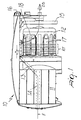
- 10 generally designates a conventional weft feeder which comprises a fixed base 11 and a fixed drum 12 on which a hollow arm 13, actuated by the hollow driving shaft 14 of the feeder 10, winds in a windmilling fashion a plurality of turns of yarn F which constitute a weft reserve RT.
- the turns of the reserve RT unwind from the free end of the drum in the advancement direction DS under the control of a braking means (not shown) which is supported by a supporting ring 15, whose axial position can be changed by means of a knob 16 in order to adjust the braking action.
- a braking means (not shown) which is supported by a supporting ring 15, whose axial position can be changed by means of a knob 16 in order to adjust the braking action.
- a movement system is associated with the drum 12 and is suitable to move the turns wound by the windmilling arm 13 from the base toward the free end of the drum 12, keeping them separated by an extent s, termed separation pitch, which can vary within preset limits.
- said movement system is constituted by a set of movement rods 17 which partially and cyclically protrude from corresponding slots 18 provided in the cylindrical surface of the drum 12.
- the rods 17 are individually connected, by means of respective spokes 19, to a hub 20 which is rotationally coupled, with a rolling bearing 22 interposed, to a bush which is keyed to the driving shaft 14 and whose axis is oblique with respect to the axis "a" of said driving shaft.
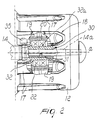
- an improved bush generally designated by the reference numeral 30, which comprises a first bush body 31 which is substantially semicylindrical ( Figures 3 and 4) and a second bush body 32 which is cylindrical and hollow and whose external surface 32a is inclined with respect to the axis of the driving shaft 14.
- the first bush body 31 is adapted to be detachably associated on a recessed part of the driving shaft 14 in order to delimit on said shaft an eccentric portion 14a which is suitable to receive the second cylindrical and hollow bush body 32 fitted thereon.
- the first bush body 31 has, in cross-section, a crescent-shaped profile ( Figures 4 and 6) which is internally delimited by a portion of the external circumference Ce of the driving shaft 14 and externally delimited by a portion of the internal circumference Ci of the second bush body 32; the two circumferences are tangent in a point P which is diametrically opposite to the part of the shaft portion 14 that receives said first bush body 31.
- the first bush body 31 is made of plastics, typically chosen in the group that comprises acetal resins and the material known by the acronym ABS (acrylonitrile-butadiene-styrene) and has a pin 33 which protrudes radially toward the concave part of said body.
- a corresponding radial hole 34 of the shaft 14 cooperates with said pin and receives it in order to prevent said first bush body 31 from performing angular movements, maintaining and therefore ensuring its phasing with respect to eccentric balancing masses 35 provided in the shaft 14 ( Figure 2).
Landscapes
- Engineering & Computer Science (AREA)
- Textile Engineering (AREA)
- Looms (AREA)
Applications Claiming Priority (2)
| Application Number | Priority Date | Filing Date | Title |
|---|---|---|---|
| ITTO980124 IT245866Y1 (it) | 1998-07-03 | 1998-07-03 | Alimentatore di trama per telai di tessitura con mezzi perfezionatidi avanzamento e separazione delle spire della riserva di trama |
| ITTO980124U | 1998-07-03 |
Publications (2)
| Publication Number | Publication Date |
|---|---|
| EP0968949A1 true EP0968949A1 (fr) | 2000-01-05 |
| EP0968949B1 EP0968949B1 (fr) | 2002-10-02 |
Family
ID=11416436
Family Applications (1)
| Application Number | Title | Priority Date | Filing Date |
|---|---|---|---|
| EP19990112756 Expired - Lifetime EP0968949B1 (fr) | 1998-07-03 | 1999-07-01 | Fournisseur de trame pour métiers à tisser avec des moyens améliorés pour l'avancement et la séparation des boucles des fils de réserve |
Country Status (3)
| Country | Link |
|---|---|
| EP (1) | EP0968949B1 (fr) |
| DE (1) | DE69903223T2 (fr) |
| IT (1) | IT245866Y1 (fr) |
Cited By (3)
| Publication number | Priority date | Publication date | Assignee | Title |
|---|---|---|---|---|
| CN110172768A (zh) * | 2019-06-19 | 2019-08-27 | 苏州济洋纺织机械有限公司 | 一种纱线热定型装置 |
| EP3587643A1 (fr) | 2018-06-28 | 2020-01-01 | Memminger-IRO GmbH | Appareil d'alimentation en fil et système doté d'un appareil d'alimentation en fil |
| CN116334803A (zh) * | 2021-12-24 | 2023-06-27 | 张家港市德胜染整有限责任公司 | 一种纱线膨化定型机 |
Citations (3)
| Publication number | Priority date | Publication date | Assignee | Title |
|---|---|---|---|---|
| FR2267270A1 (fr) * | 1974-04-10 | 1975-11-07 | Calamani Sergio | |
| EP0164033A2 (fr) | 1984-06-04 | 1985-12-11 | ROJ ELECTROTEX S.p.A. | Fournisseur de trame pour métiers à tisser |
| EP0643004A1 (fr) * | 1993-09-10 | 1995-03-15 | L.G.L. ELECTRONICS S.p.A. | Dispositif pour séparer les boucles de fil de réserve sur les fournisseurs pour métiers à tisser ou similaires |
-
1998
- 1998-07-03 IT ITTO980124 patent/IT245866Y1/it active
-
1999
- 1999-07-01 DE DE1999603223 patent/DE69903223T2/de not_active Expired - Lifetime
- 1999-07-01 EP EP19990112756 patent/EP0968949B1/fr not_active Expired - Lifetime
Patent Citations (3)
| Publication number | Priority date | Publication date | Assignee | Title |
|---|---|---|---|---|
| FR2267270A1 (fr) * | 1974-04-10 | 1975-11-07 | Calamani Sergio | |
| EP0164033A2 (fr) | 1984-06-04 | 1985-12-11 | ROJ ELECTROTEX S.p.A. | Fournisseur de trame pour métiers à tisser |
| EP0643004A1 (fr) * | 1993-09-10 | 1995-03-15 | L.G.L. ELECTRONICS S.p.A. | Dispositif pour séparer les boucles de fil de réserve sur les fournisseurs pour métiers à tisser ou similaires |
Cited By (3)
| Publication number | Priority date | Publication date | Assignee | Title |
|---|---|---|---|---|
| EP3587643A1 (fr) | 2018-06-28 | 2020-01-01 | Memminger-IRO GmbH | Appareil d'alimentation en fil et système doté d'un appareil d'alimentation en fil |
| CN110172768A (zh) * | 2019-06-19 | 2019-08-27 | 苏州济洋纺织机械有限公司 | 一种纱线热定型装置 |
| CN116334803A (zh) * | 2021-12-24 | 2023-06-27 | 张家港市德胜染整有限责任公司 | 一种纱线膨化定型机 |
Also Published As
| Publication number | Publication date |
|---|---|
| ITTO980124V0 (it) | 1998-07-03 |
| DE69903223D1 (de) | 2002-11-07 |
| ITTO980124U1 (it) | 2000-01-03 |
| EP0968949B1 (fr) | 2002-10-02 |
| DE69903223T2 (de) | 2003-08-14 |
| IT245866Y1 (it) | 2002-03-26 |
Similar Documents
| Publication | Publication Date | Title |
|---|---|---|
| US4498639A (en) | Weft predelivery and measuring device for a shuttleless loom | |
| EP0164033B1 (fr) | Fournisseur de trame pour métiers à tisser | |
| EP3257984B1 (fr) | Dispositif d'alimentation de fil avec bobine d'enroulement de fil motorisée | |
| US3791598A (en) | Thread delivery device | |
| EP0968949B1 (fr) | Fournisseur de trame pour métiers à tisser avec des moyens améliorés pour l'avancement et la séparation des boucles des fils de réserve | |
| US5890670A (en) | Device for spacing turns of thread for weft feeders | |
| GB2061331A (en) | Open end spinning rotor consisting of a base body and a rotor body | |
| EP0698135B1 (fr) | Alimenteur de trame pourvu d'un separateur de tours s'adaptant sur des metiers a tisser a jet d'air a vitesse d'insertion elevee | |
| CN112623822A (zh) | 一种具有翻转进卸料功能的纺织用卷布装置 | |
| KR860000428A (ko) | 직기용 위사공급기 | |
| PL106060B1 (pl) | Urzadzenie do magazynowania zapasu przedzy podawanej do krosna tkackiego lub maszyny dziewiarskiej zasilanej przedza | |
| EP0643004B1 (fr) | Dispositif pour séparer les boucles de fil de réserve sur les fournisseurs pour métiers à tisser ou similaires | |
| US5590693A (en) | Rotatable thread arrester for weft feeders for air-jet looms | |
| GB2031966A (en) | Thread storage and delivery device | |
| EP3199680B1 (fr) | Dispositif de récupération de fil pour appareils de textile | |
| EP0884263B1 (fr) | Frein de fil modulé à ajustage automatique pour un fournisseur de trame | |
| US4493347A (en) | Weft insertion device for a band-gripper weaving machine | |
| EP0962416B1 (fr) | Dispositif pour la retenue flexible d'un système flottant pour l'avancement des enroulements de fil de réserve dans les délivreurs de fil pour métiers à tisser | |
| GB2088910A (en) | Method of controlling weft threads and rotary measuring device for performing said method | |
| US4130143A (en) | Band guide roller for band-gripper looms | |
| KR100457304B1 (ko) | 실 공급장치 및 실 제동 몸체 | |
| EP0405382A1 (fr) | Dispositif d'alimentation de fil de trame avec tambour comme dévidoir pour machines de tissage à jet | |
| KR960012279B1 (ko) | 분사식 직기용 위사저류(緯絲貯留) 장치 | |
| EP0326960A1 (fr) | Accumulateur de trame pour métiers à tisser | |
| US2637348A (en) | Harness cam and treadle means for looms |
Legal Events
| Date | Code | Title | Description |
|---|---|---|---|
| PUAI | Public reference made under article 153(3) epc to a published international application that has entered the european phase |
Free format text: ORIGINAL CODE: 0009012 |
|
| AK | Designated contracting states |
Kind code of ref document: A1 Designated state(s): BE DE |
|
| AX | Request for extension of the european patent |
Free format text: AL;LT;LV;MK;RO;SI |
|
| 17P | Request for examination filed |
Effective date: 20000228 |
|
| AKX | Designation fees paid |
Free format text: BE DE |
|
| GRAG | Despatch of communication of intention to grant |
Free format text: ORIGINAL CODE: EPIDOS AGRA |
|
| 17Q | First examination report despatched |
Effective date: 20011025 |
|
| GRAG | Despatch of communication of intention to grant |
Free format text: ORIGINAL CODE: EPIDOS AGRA |
|
| GRAH | Despatch of communication of intention to grant a patent |
Free format text: ORIGINAL CODE: EPIDOS IGRA |
|
| GRAH | Despatch of communication of intention to grant a patent |
Free format text: ORIGINAL CODE: EPIDOS IGRA |
|
| GRAA | (expected) grant |
Free format text: ORIGINAL CODE: 0009210 |
|
| AK | Designated contracting states |
Kind code of ref document: B1 Designated state(s): BE DE |
|
| REF | Corresponds to: |
Ref document number: 69903223 Country of ref document: DE Date of ref document: 20021107 |
|
| PLBE | No opposition filed within time limit |
Free format text: ORIGINAL CODE: 0009261 |
|
| STAA | Information on the status of an ep patent application or granted ep patent |
Free format text: STATUS: NO OPPOSITION FILED WITHIN TIME LIMIT |
|
| 26N | No opposition filed |
Effective date: 20030703 |
|
| PGFP | Annual fee paid to national office [announced via postgrant information from national office to epo] |
Ref country code: DE Payment date: 20170717 Year of fee payment: 19 |
|
| PGFP | Annual fee paid to national office [announced via postgrant information from national office to epo] |
Ref country code: BE Payment date: 20170717 Year of fee payment: 19 |
|
| REG | Reference to a national code |
Ref country code: DE Ref legal event code: R119 Ref document number: 69903223 Country of ref document: DE |
|
| REG | Reference to a national code |
Ref country code: BE Ref legal event code: MM Effective date: 20180731 |
|
| PG25 | Lapsed in a contracting state [announced via postgrant information from national office to epo] |
Ref country code: DE Free format text: LAPSE BECAUSE OF NON-PAYMENT OF DUE FEES Effective date: 20190201 |
|
| PG25 | Lapsed in a contracting state [announced via postgrant information from national office to epo] |
Ref country code: BE Free format text: LAPSE BECAUSE OF NON-PAYMENT OF DUE FEES Effective date: 20180731 |