EP0970595B1 - Dispositif et procédé pour déterminer une position virtuelle - Google Patents
Dispositif et procédé pour déterminer une position virtuelle Download PDFInfo
- Publication number
- EP0970595B1 EP0970595B1 EP99112635A EP99112635A EP0970595B1 EP 0970595 B1 EP0970595 B1 EP 0970595B1 EP 99112635 A EP99112635 A EP 99112635A EP 99112635 A EP99112635 A EP 99112635A EP 0970595 B1 EP0970595 B1 EP 0970595B1
- Authority
- EP
- European Patent Office
- Prior art keywords
- vehicle
- working implement
- receiving unit
- reference point
- satellite receiving
- Prior art date
- Legal status (The legal status is an assumption and is not a legal conclusion. Google has not performed a legal analysis and makes no representation as to the accuracy of the status listed.)
- Expired - Lifetime
Links
- 238000000034 method Methods 0.000 title claims description 10
- 238000006243 chemical reaction Methods 0.000 claims description 27
- 238000011156 evaluation Methods 0.000 claims description 22
- 239000011159 matrix material Substances 0.000 claims description 9
- 230000009466 transformation Effects 0.000 claims description 9
- 230000008569 process Effects 0.000 claims description 5
- 230000001105 regulatory effect Effects 0.000 claims description 2
- 238000005520 cutting process Methods 0.000 description 12
- 239000003337 fertilizer Substances 0.000 description 8
- 230000007480 spreading Effects 0.000 description 5
- 238000003892 spreading Methods 0.000 description 5
- 230000005540 biological transmission Effects 0.000 description 3
- 238000004364 calculation method Methods 0.000 description 2
- 230000008859 change Effects 0.000 description 2
- 230000008878 coupling Effects 0.000 description 2
- 238000010168 coupling process Methods 0.000 description 2
- 238000005859 coupling reaction Methods 0.000 description 2
- 101100498160 Mus musculus Dach1 gene Proteins 0.000 description 1
- 230000008901 benefit Effects 0.000 description 1
- 238000004422 calculation algorithm Methods 0.000 description 1
- 239000003795 chemical substances by application Substances 0.000 description 1
- 238000010276 construction Methods 0.000 description 1
- 238000009795 derivation Methods 0.000 description 1
- 238000010586 diagram Methods 0.000 description 1
- 238000009826 distribution Methods 0.000 description 1
- 238000003306 harvesting Methods 0.000 description 1
- 230000006872 improvement Effects 0.000 description 1
- 238000009434 installation Methods 0.000 description 1
- 230000007246 mechanism Effects 0.000 description 1
- QHGUCRYDKWKLMG-UHFFFAOYSA-N octopamine Chemical compound NCC(O)C1=CC=C(O)C=C1 QHGUCRYDKWKLMG-UHFFFAOYSA-N 0.000 description 1
- 229960001576 octopamine Drugs 0.000 description 1
- 239000002689 soil Substances 0.000 description 1
- 229910000679 solder Inorganic materials 0.000 description 1
- 239000007921 spray Substances 0.000 description 1
- 239000000725 suspension Substances 0.000 description 1
- 230000001960 triggered effect Effects 0.000 description 1
- 238000003079 width control Methods 0.000 description 1
Images


Classifications
-
- A—HUMAN NECESSITIES
- A01—AGRICULTURE; FORESTRY; ANIMAL HUSBANDRY; HUNTING; TRAPPING; FISHING
- A01B—SOIL WORKING IN AGRICULTURE OR FORESTRY; PARTS, DETAILS, OR ACCESSORIES OF AGRICULTURAL MACHINES OR IMPLEMENTS, IN GENERAL
- A01B79/00—Methods for working soil
- A01B79/005—Precision agriculture
Definitions
- the invention relates to an agricultural vehicle or implement with a satellite receiver unit for position determination and a method for position determination according to the preamble of claims 1 and 13.
- satellite navigation systems such as the Global Positioning System (GPS) is already being created for agricultural vehicles or work equipment of crop registers and soil height profiles as well as for the control of fertilizer application known.
- GPS Global Positioning System
- DGPS satellite navigation systems
- Evaluation units available, which ensure an accuracy of the position determination, i.e. of determination the position of a GPS antenna, reach in the centimeter range.
- DE 196 47 523 describes an agricultural vehicle with a satellite navigation system known.
- the vehicle described there has a processing device, where it is proposed to position the reference point on the processing device determine instead of, for example, the position of the vehicle center.
- the satellite receiving unit GPS antenna
- Reasons for the fact that the GPS antenna is not directly at the location whose position is actually to be determined can be attached, for example, lack of mechanical attachment options, Shading of the signals by the vehicle itself, the risk of damage or severe Wear.
- the reference point whose position is to be determined is spatial from the GPS antenna, whose position is actually using the satellite navigation system is determined at a distance (D) away.
- the processing device is not rigidly connected to the vehicle, but is, for example, height-adjustable on it is arranged, one gets from DE 196 47 523 the hint to provide a sensor that the Height change of the processing device relative to the vehicle measures, and this measured Height change in the coordinate determination described above as a correction to let.
- GPS antenna iteratively determine the direction of travel and the orientation of the vehicle, however this method is inaccurate and fails when the vehicle is stationary and when starting from the Stand.
- the direction of travel is correct in some applications (for example when driving in the crab or on a slope) does not match the longitudinal direction of the vehicle.
- the agricultural vehicle has at least one sensor (S, S1, S2, S3) for determining the position of the vehicle.
- Position means the orientation of the vehicle and the orientation in the horizontal plane of the terrestrial reference system (x, y, z), whereby orientation means the angle ( ⁇ ) that the longitudinal direction of the vehicle, for example, with the NS direction (y coordinate of the terrestrial reference system) forms and orientation means the direction to which, for example, the front of the vehicle is pointing.
- the position of the vehicle also means the longitudinal or transverse inclination ( ⁇ , ⁇ ) of the vehicle relative to the vertical direction (Z coordinate) of the reference system.
- the coordinates of the GPS antenna are denoted by (X A , Y A , Z A ); the coordinates of the reference point with (X P , Y P , Z P ).
- the sensor for determining the orientation ( ⁇ ) of the vehicle in the horizontal plane is preferred a mechanical gyrocompass known to the person skilled in the art or a laser gyro is used.
- Solder pendulums are preferably used as sensors for the longitudinal or transverse inclination ( ⁇ , ⁇ ) used with electrical signal generators, which are also known to the person skilled in the art.
- the person skilled in the art can also use a single sensor which is able to detect the various Detect deviations ( ⁇ , ⁇ , ⁇ ).
- vehicle-specific basic conversion variables (X P0 -X A0 ; Y P0 -Y A0 ; Z P0 -Z A0 ; ⁇ 0 ; ⁇ 0 ; ⁇ 0 ; d 1 ; d 2 ; d 3 ) are provided according to the invention, which reflect the geometric relationships of the arrangement of the reference point and GPS antenna on the vehicle for a specific, aligned position of the vehicle.
- the aligned position of the vehicle is preferably the one where the longitudinal direction of the vehicle is oriented in the NS direction with the front facing north and where there is no longitudinal or transverse inclination of the vehicle, ie for the excellent position it is assumed that the vehicle is on a flat field that is not inclined in any direction.
- These basic conversion variables are part of a vehicle specification.
- a fictional and for the agricultural vehicle fixed Cartesian coordinate system can be defined in relation to the vehicle.
- the axes this coordinate system are denoted by (bx, by, bz).
- the coordinate origin (zero point) this coordinate system is placed at the location of the GPS antenna. It is crucial that this coordinate system is firmly connected to the vehicle, i.e. that for this coordinate system all horizontal and vertical changes of location as well as all rotations and inclinations of the vehicle apply.
- the vehicle-specific basic conversion variables (X P0 -X A0 ; Y P0 -Y A0 ; Z P0 -Z A0 ; ⁇ 0 ; ⁇ 0 ; ⁇ 0 , d 1 , d 2 , d 3 ) are in a memory of the evaluation unit or in another Memory of the vehicle to which the evaluation unit has access can be stored.
- the sensor or sensors now each detect a deviation ( ⁇ , ⁇ , ⁇ ) of the vehicle position from the aligned position, which is described in detail above.
- the evaluation unit (AWE) now uses these deviations ( ⁇ , ⁇ , ⁇ ) and taking into account the vehicle-specific basic conversion variables ( ⁇ 0 , ⁇ 0 , ⁇ 0 , d 1 , d 2 , d 3 ) to determine the current conversion variable for determining the Coordinates (X P , Y P , Z P ) of the reference point spatially spaced from the satellite receiving unit from the known position coordinates (X A , Y A , Z A ) of the satellite receiving unit (GPS antenna).
- the determination of the absolute position for the location of the GPS antenna is done by one well-known computing algorithm that processes the transmission data from GPS satellites. This is the Known in the art and can be done with sufficient accuracy.
- the satellite receiving unit can already include an evaluation unit that already contains the GPS transmission data Position data for the location of the GPS antenna determined, from which then in this evaluation unit or in a separate evaluation unit according to the invention the position of the reference point is determined.
- it is also within the scope of the invention if only one evaluation unit is provided, which does not belong directly to the satellite receiving unit, wherein also the GPS transmission data for determining the position of the location of the GPS antenna to this evaluation unit be directed.
- a transformation matrix is calculated from the conversion variables determined according to the invention and this transformation matrix is used to determine the position vector (X P , Y P , Z) from the known position vector (X A , Y A , Z A ) of the GPS antenna P ) of the reference point.
- the position determination according to the prior art thus deviates by 77 for the z coordinate cm and for the y coordinate by 39 cm from the actual value. These deviations are greater than the inaccuracy of satellite navigation itself.
- the invention enables the exact position determination of a spatially from the GPS antenna spaced reference point for a wide variety of agricultural locations Vehicle or implement in the terrestrial reference system. This allows harvest registers to be made and create floor height profiles much better.
- the invention also provides a particular improvement for automatic steering systems that, for example, a combine harvester automatically steers along a virtual grain edge can be.
- the virtual grain edge is made from previously recorded reference position data derived and compared with the determined, current reference position of the cutting edge.
- a control signal is generated from the deviations in the vehicle direction and the reference point distance determined for the automatic steering system.
- the invention provides a further advantage for the control of distribution devices that are used for application of agents, for example sprays or fertilizers, are suitable for fields.
- an automatic working width control can be set up very easily.
- the reference point is according to the invention placed in the place of the outermost application position, so the working width If the reference point is exceeded, the stored stroke limits are reduced accordingly and the course of the stroke limits are automatically dynamically adjusted.
- By recording the reference points can also be recorded here using a virtual machining edge on which a vehicle, based on the current working width, during the next drive along can be automatically steered along. If you set other reference points, for example in the working direction, at the beginning or at the end of the application area, see above can be easily switched on and off of the implement become.
- the invention can also be advantageous on agricultural implement combinations, such as towing vehicles with one decoupled from the satellite reception antenna directionally or inclination Implement, such as an attached fertilizer control or one Syringe. Additional own inclination or Direction sensors attached, which advantageously align the implement determine the coupling point with the towing vehicle.
- the base distance (D) of the virtual reference point from the receiving antenna then consists of individual partial distances that are specific to the respective implement and the tractor are together and can be advantageously calculated over a defined coupling point between the tractor and the implement.
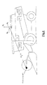
- FIG. A combine is shown with attached cutter.
- the GPS antenna is located on the roof of the combine at a height of approx. 4 m.
- the reference point is placed on the outside of the cutting unit at a height of 1m.
- This side view shows the combine in the yz plane of the terrestrial coordinate system.
- the fictitious coordinate system (bx, by, bz) that is firmly connected to the combine is also shown.
- the distance between the location of the GPS antenna and the reference point is designated by the reference symbol (D). In this side view, however, only the projection (d 2 ) of the distance line (D) on the yz plane can be represented.
- FIGS. 2, 4, 6, the combine harvester is in an aligned zero position in the associated one Level shown.
- the representations are schematic and are not to scale.
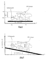
- FIG. 2 shows the top view of a combine harvester in an aligned zero position.
- the GPS antenna is on the roof of the combine.
- the position shown is selected so that the vehicle's longitudinal direction is parallel to the N-S direction (y coordinate) and the cutting unit faces north.
- N-S direction y coordinate
- Another aligned position can be selected within the scope of the invention.
- the choice of this location for easy determination of the vehicle-specific basic conversion values is only one Convention. However, the aligned location should take into account conventions of the satellite navigation system used are chosen so that the determination of the basic conversion variables is as simple as possible.
- the base conversion values are called “vehicle-specific” referred to, since once the aligned situation is determined by convention, by the location of the GPS antenna on the vehicle and the desired position of the reference point can be clearly determined for this "vehicle-specific" constellation.
- the determination of the base conversion values can be done by measuring and / or mathematical calculations.
- the difference (X P0 -X A0 ) between the x coordinate of the reference point and the x coordinate of the GPS antenna is 3.5 m; the difference (Y P0 -Y A0 ) between the y coordinate of the reference point and the y coordinate of the GPS antenna is 5 m.
- d 1 is the projection of the distance line (D) between the GPS antenna and the reference point on the horizontal plane (x, y). The same applies to d 2 and d 3 with respect to the respective levels.
- ⁇ 0 denotes the angle between d 1 and the NS direction / vehicle longitudinal direction.
- Fig. 4 shows the side view (yz plane) of the combine in the aligned position.
- the GPS antenna is on the roof of the combine harvester at a height of 4 m, the reference point on the cutting unit at a height of 1 m.
- the difference (Y P0 -Y A0 ) between the y coordinate of the reference point and the y coordinate of the GPS antenna is, as can already be seen from FIG. 2, 5 m; the difference (Z P0 -Z A0 ) between the z coordinate of the reference point and the z coordinate of the GPS antenna is equal to -3 m.
- d 2 (3 2 + 5 2 )
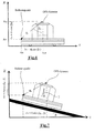
- Fig. 6 shows the side view (x, z plane) of the combine in the aligned position.
- the GPS antenna is on the roof of the combine harvester at a height of 4 m, the reference point on the cutting unit at a height of 1 m.
- the difference (X P0 -X A0 ) between the x coordinate of the reference point and the x coordinate of the GPS antenna is, as can already be seen in FIG. 2, 3.5 m; the difference (Z P0 -Z A0 ) between the z coordinate of the reference point and the z coordinate of the GPS antenna is equal to -3 m.
- d 3 (3 2 + 3, 5 2 )
- m 2 4.61m
- ⁇ 0 denotes the angle between d 3 and the vertical / z direction.
- the deviations ( ⁇ , ⁇ , ⁇ ) are measured and according to the invention using the basic conversion quantities described above in each case current conversion variables for the determination of the reference point determined.
- Fig. 3 shows the top view of a combine deviating from the aligned zero position on a flat field.
- Fig. 5 shows a side view of a combine deviating from the aligned zero position, which drives up a slope in the SN direction.
- the invention is not restricted to the determination of a reference point. Rather, two or more reference points can be provided. This can also be inside the vehicle instead of the processing device. Furthermore, it is provided that the reference point or reference points as virtual reference points outside of the vehicle and outside of the processing device.
- a reference line, reference surface or reference volume consisting of two or more reference points can be determined.
- Such a virtual reference surface in front of the cutting mechanism is shown in FIG.
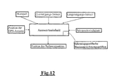
- the evaluation unit (AR) when determining a virtual reference point at least one parameter of the Vehicle such as the driving speed is taken into account, so that the location of the virtual Reference point relative to the satellite receiver unit (GPS antenna) depending on at least one parameter can be dynamically controlled. This is based on the driving speed in 9 and 10 shown. At a higher driving speed, you can practically continue drive with foresight.
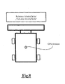
- At least one position parameter (relative articulation angle of the trailer to the towing vehicle, relative height of the three-point hitch, relative feed channel angle, and other) of a processing device attached to the vehicle from the evaluation unit (AWE) is taken into account so that the position of the virtual reference point to the satellite receiving unit (GPS antenna) can be dynamically regulated depending on this position parameter.
- Fig. 11 shows a tractor with a fertilizer spreader, for example. It is intended the position of the virtual reference point from the rotation speed of the spreading disc or depending on the working width of the spreader, so that the reference point in each case lies at the edge of the spreading area. So that the theoretical working width can be determined even better position parameters of the three-point hitch are also included in the calculation of the Reference point taken into account.
Landscapes
- Life Sciences & Earth Sciences (AREA)
- Engineering & Computer Science (AREA)
- Mechanical Engineering (AREA)
- Soil Sciences (AREA)
- Environmental Sciences (AREA)
- Position Fixing By Use Of Radio Waves (AREA)
- Guiding Agricultural Machines (AREA)
- Navigation (AREA)
- Control Of Position, Course, Altitude, Or Attitude Of Moving Bodies (AREA)
Claims (14)
- Véhicule agricole ou outil agricole équipé d'une unité de réception satellite pour la détermination de la position dans le système de référence terrestre tridimensionnel, le véhicule agricole ou l'outil comportant une unité de traitement (AWE) qui, à partir des données reçues de l'unité de réception satellite, détermine la position absolue d'au moins un point de référence séparé dans l'espace du lieu de l'unité de réception satellite, la distance (D) dans l'espace entre l'unité de réception satellite et le point de référence étant connue en valeur, au moins un capteur (S, S1, S2, S3) pour la détermination de la position du véhicule - c'est-à-dire du positionnement et de l'orientation du véhicule dans le plan horizontal du système de référence terrestre et/ou de l'inclinaison longitudinale et transversale du véhicule par rapport à la direction verticale du système de référence - étant prévu, au moins une grandeur de conversion de base (XP0, XA0, YP0, YA0, ZP0, ZA0, 0, α0, β0, d1, d2, d3) spécifique au véhicule pouvant être mémorisée dans une mémoire de l'unité de traitement (AWE) ou dans une mémoire autre disposée sur le véhicule ou sur l'outil pour une position repérée donnée du véhicule - de préférence la direction longitudinale du véhicule dans la direction N-S, avec l'avant tournée vers le nord et sans inclinaison longitudinale ou transversale du véhicule -, et le capteur (les capteurs) détectant au moins un écart (, α, β) de la position par rapport à la position zéro, caractérisé en ce que, sur la base de cet écart (, α, β) et en tenant compte d'au moins une grandeur de conversion de base (0, α0, β0, d1, d2, d3) spécifique au véhicule, on calcule la grandeur de conversion actuelle pour la détermination des coordonnées (XP, YP, ZP) du point de référence éloigné de l'unité de réception satellite à partir des coordonnées de position (XA, YA, ZA) connues de l'unité de réception satellite.
- Véhicule agricole ou outil agricole selon la revendication 1, caractérisé en ce que l'unité de traitement détermine à partir des grandeurs de conversion une matrice de transformation, et, avec cette matrice de transformation, détermine le vecteur de position (XP, YP, ZP) du point de référence sur la base du vecteur de position (XA, YA, ZA) connu de l'unité de réception satellite.
- Véhicule agricole ou outil agricole selon au moins une des revendications 1 et 2, caractérisé en ce qu'il est prévu un détecteur de direction, tel que par exemple un compas, comme capteur (S1) pour déterminer l'orientation () du véhicule dans le plan horizontal du système de référence terrestre.
- Véhicule agricole ou outil agricole selon au moins une des revendications précédentes, caractérisé en ce qu'il est prévu un détecteur d'inclinaison, tel que par exemple un pendule avec un transmetteur de signal électrique, comme capteur (S2) pour déterminer l'inclinaison longitudinale (α) du véhicule par rapport à la direction verticale du système de référence terrestre.
- Véhicule agricole ou outil agricole selon au moins une des revendications précédentes, caractérisé en ce qu'il est prévu un détecteur d'inclinaison, tel que par exemple un pendule avec un transmetteur de signal électrique, comme capteur (S3) pour déterminer l'inclinaison transversale (β) du véhicule par rapport à la direction verticale du système de référence terrestre.
- Véhicule agricole ou outil agricole selon au moins une des revendications 1 et 2, caractérisé en ce qu'il est prévu un capteur (S) pour déterminer l'orientation () du véhicule dans le plan horizontal du système de référence terrestre ainsi que l'inclinaison longitudinale (α) voire l'inclinaison transversale (β) du véhicule par rapport à la direction verticale du système de référence terrestre.
- Véhicule agricole ou outil agricole selon une des revendications précédentes, caractérisé en ce qu'une ligne de référence définie par deux points de référence ou plus peut être déterminée.
- Véhicule agricole ou outil agricole selon une des revendications précédentes, caractérisé en ce qu'une surface de référence définie par trois points de référence ou plus peut être déterminée.
- Véhicule agricole ou outil agricole selon une des revendications précédentes, caractérisé en ce qu'un volume de référence défini par trois points de référence ou plus peut être déterminé.
- Véhicule agricole ou outil agricole selon une des revendications précédentes, caractérisé en ce qu'au moins un paramètre de travail d'un outil monté sur le véhicule ou tracté est pris en compte par l'unité de traitement (AWE), de sorte que la position du point de référence virtuel par rapport à l'unité de réception satellite peut être calculée en fonction de ce paramètre de travail.
- Véhicule agricole ou outil agricole selon une des revendications précédentes, caractérisé en ce que l'unité de traitement (AWE) prend en compte la vitesse du véhicule dans la détermination d'un point de référence virtuel, de sorte que la position du point de référence virtuel par rapport à l'unité de réception satellite peut être réglée dynamiquement en fonction de la vitesse du véhicule.
- Véhicule agricole ou outil agricole selon une des revendications précédentes, caractérisé en ce que différents points de référence peuvent être désactivés ou activés par l'utilisateur ou de manière automatique par le processus de travail.
- Procédé de détermination de la position pour un véhicule agricole ou un outil agricole équipé d'une unité de réception satellite pour la détermination de la position dans un système de référence terrestre tridimensionnel, le véhicule ou l'outil agricole comportant une unité de traitement (AWE) qui, à partir des données reçues de l'unité de réception satellite, détermine la position absolue d'au moins un point de référence séparé dans l'espace du lieu de l'unité de réception satellite, la distance (D) dans l'espace entre l'unité de réception satellite et le point de référence étant connue en valeur, au moins un capteur (S, S1, S2, S3) pour la détermination de la position du véhicule - c'est-à-dire du positionnement et de l'orientation du véhicule dans le plan horizontal du système de référence terrestre et/ou de l'inclinaison longitudinale et transversale du véhicule par rapport à la direction verticale du système de référence - étant prévu, au moins une grandeur de conversion de base (XP0, XA0, YP0, YA0, ZP0, ZA0, 0, α0, β0, d1, d2, d3) spécifique au véhicule pouvant être mémorisée dans une mémoire de l'unité de traitement (AWE) ou dans une autre mémoire disposée sur le véhicule ou sur l'outil, pour une position repérée donnée du véhicule - de préférence la direction longitudinale du véhicule dans la direction N-S, avec l'avant tournée vers le nord et sans inclinaison longitudinale ou transversale du véhicule -, et le capteur (les capteurs) détectant au moins un écart (, α, β) de la position par rapport à la position zéro, caractérisé en ce que, sur la base de cet écart (, α, β) et en tenant compte d'au moins une grandeur de conversion de base (0, α0, β0, d1, d2, d3) spécifique au véhicule, on calcule la grandeur de conversion actuelle pour la détermination des coordonnées (XP, YP, ZP) du point de référence éloigné de l'unité de réception satellite sur la base des coordonnées de position (XA, YA, ZA) connues de l'unité de réception satellite.
- Procédé de détermination de la position pour un véhicule agricole ou un outil agricole selon la revendication 13, caractérisé en ce que l'unité de traitement (AWE) détermine à partir des grandeurs de conversion une matrice de transformation, et, avec cette matrice de transformation, détermine le vecteur de position (XP, YP, ZP) du point de référence sur la base du vecteur de position (XA, YA, ZA) connu de l'unité de réception satellite.
Applications Claiming Priority (2)
| Application Number | Priority Date | Filing Date | Title |
|---|---|---|---|
| DE19830858 | 1998-07-10 | ||
| DE19830858A DE19830858A1 (de) | 1998-07-10 | 1998-07-10 | Vorrichtung und Verfahren zur Bestimmung einer virtuellen Position |
Publications (3)
| Publication Number | Publication Date |
|---|---|
| EP0970595A1 EP0970595A1 (fr) | 2000-01-12 |
| EP0970595B1 true EP0970595B1 (fr) | 2003-04-16 |
| EP0970595B2 EP0970595B2 (fr) | 2007-04-25 |
Family
ID=7873562
Family Applications (1)
| Application Number | Title | Priority Date | Filing Date |
|---|---|---|---|
| EP99112635A Expired - Lifetime EP0970595B2 (fr) | 1998-07-10 | 1999-07-02 | Dispositif et procédé pour déterminer une position virtuelle |
Country Status (5)
| Country | Link |
|---|---|
| US (1) | US6345231B2 (fr) |
| EP (1) | EP0970595B2 (fr) |
| BR (1) | BR9902661A (fr) |
| DE (2) | DE19830858A1 (fr) |
| DK (1) | DK0970595T4 (fr) |
Families Citing this family (95)
| Publication number | Priority date | Publication date | Assignee | Title |
|---|---|---|---|---|
| DE10064861A1 (de) * | 2000-12-23 | 2002-06-27 | Claas Selbstfahr Erntemasch | Vorrichtung und Verfahren zur automatischen Steuerung einer Überladeeinrichtung an landwirtschaftlichen Erntemaschinen |
| US6682416B2 (en) | 2000-12-23 | 2004-01-27 | Claas Selbstfahrende Erntemaschinen Gmbh | Automatic adjustment of a transfer device on an agricultural harvesting machine |
| DE10134141A1 (de) * | 2001-07-13 | 2003-02-06 | Deere & Co | Verteilvorrichtung für aus einer Erntemaschine austretendes Häckselgut |
| US7948769B2 (en) * | 2007-09-27 | 2011-05-24 | Hemisphere Gps Llc | Tightly-coupled PCB GNSS circuit and manufacturing method |
| US6718246B2 (en) * | 2002-04-24 | 2004-04-06 | Caterpillar Inc | Automatic implement control for spreading material with a work machine |
| JP2004125580A (ja) * | 2002-10-02 | 2004-04-22 | Hitachi Constr Mach Co Ltd | 作業機械の位置計測システム |
| DE10250694B3 (de) | 2002-10-31 | 2004-02-12 | CNH Österreich GmbH | Verfahren zur Steuerung eines landwirtschaftlichen Nutzfahrzeuges |
| US7885745B2 (en) * | 2002-12-11 | 2011-02-08 | Hemisphere Gps Llc | GNSS control system and method |
| US7689354B2 (en) | 2003-03-20 | 2010-03-30 | Hemisphere Gps Llc | Adaptive guidance system and method |
| US7400956B1 (en) | 2003-03-20 | 2008-07-15 | Hemisphere Gps Inc. | Satellite position and heading sensor for vehicle steering control |
| US7162348B2 (en) | 2002-12-11 | 2007-01-09 | Hemisphere Gps Llc | Articulated equipment position control system and method |
| US6738695B1 (en) * | 2002-12-16 | 2004-05-18 | Caterpillar Inc | System and method for initializing autoguidance for a mobile machine |
| US8686900B2 (en) * | 2003-03-20 | 2014-04-01 | Hemisphere GNSS, Inc. | Multi-antenna GNSS positioning method and system |
| US8634993B2 (en) | 2003-03-20 | 2014-01-21 | Agjunction Llc | GNSS based control for dispensing material from vehicle |
| US8140223B2 (en) * | 2003-03-20 | 2012-03-20 | Hemisphere Gps Llc | Multiple-antenna GNSS control system and method |
| US8594879B2 (en) * | 2003-03-20 | 2013-11-26 | Agjunction Llc | GNSS guidance and machine control |
| US8271194B2 (en) | 2004-03-19 | 2012-09-18 | Hemisphere Gps Llc | Method and system using GNSS phase measurements for relative positioning |
| US8214111B2 (en) * | 2005-07-19 | 2012-07-03 | Hemisphere Gps Llc | Adaptive machine control system and method |
| US8138970B2 (en) * | 2003-03-20 | 2012-03-20 | Hemisphere Gps Llc | GNSS-based tracking of fixed or slow-moving structures |
| US9002565B2 (en) | 2003-03-20 | 2015-04-07 | Agjunction Llc | GNSS and optical guidance and machine control |
| US8190337B2 (en) * | 2003-03-20 | 2012-05-29 | Hemisphere GPS, LLC | Satellite based vehicle guidance control in straight and contour modes |
| US20040212533A1 (en) * | 2003-04-23 | 2004-10-28 | Whitehead Michael L. | Method and system for satellite based phase measurements for relative positioning of fixed or slow moving points in close proximity |
| US8265826B2 (en) * | 2003-03-20 | 2012-09-11 | Hemisphere GPS, LLC | Combined GNSS gyroscope control system and method |
| EP1475609B1 (fr) | 2003-05-09 | 2012-10-24 | Deere & Company | Système de compensation d'un système de référence d'un véhicule terrestre |
| DE10328395B4 (de) * | 2003-06-18 | 2010-11-11 | Gebr. Pöttinger GmbH | Verfahren zur Steuerung einer Landmaschine |
| US7058495B2 (en) * | 2003-09-04 | 2006-06-06 | Caterpillar Inc. | Work implement control system and method |
| US7593798B2 (en) * | 2003-10-30 | 2009-09-22 | Deere & Company | Vehicular guidance system having compensation for variations in ground elevation |
| US6845311B1 (en) * | 2003-11-04 | 2005-01-18 | Caterpillar Inc. | Site profile based control system and method for controlling a work implement |
| US7065440B2 (en) * | 2004-01-22 | 2006-06-20 | Trimble Navigation, Ltd | Method and apparatus for steering movable object by using control algorithm that takes into account the difference between the nominal and optimum positions of navigation antenna |
| DE102004009417A1 (de) * | 2004-02-24 | 2005-09-08 | Continental Teves Ag & Co. Ohg | Verfahren und Vorrichtung zum Bestimmen des Längsneigungswinkels eines Fahrzeugs |
| US8583315B2 (en) * | 2004-03-19 | 2013-11-12 | Agjunction Llc | Multi-antenna GNSS control system and method |
| DK1896872T3 (en) * | 2005-06-08 | 2017-01-09 | C-Dax Ltd | IMPROVEMENTS IN OR RELATING pasture management |
| US7388539B2 (en) | 2005-10-19 | 2008-06-17 | Hemisphere Gps Inc. | Carrier track loop for GNSS derived attitude |
| US7734398B2 (en) * | 2006-07-31 | 2010-06-08 | Caterpillar Inc. | System for automated excavation contour control |
| USRE48527E1 (en) | 2007-01-05 | 2021-04-20 | Agjunction Llc | Optical tracking vehicle control system and method |
| US8311696B2 (en) * | 2009-07-17 | 2012-11-13 | Hemisphere Gps Llc | Optical tracking vehicle control system and method |
| US7835832B2 (en) * | 2007-01-05 | 2010-11-16 | Hemisphere Gps Llc | Vehicle control system |
| US9615501B2 (en) * | 2007-01-18 | 2017-04-11 | Deere & Company | Controlling the position of an agricultural implement coupled to an agricultural vehicle based upon three-dimensional topography data |
| US8000381B2 (en) * | 2007-02-27 | 2011-08-16 | Hemisphere Gps Llc | Unbiased code phase discriminator |
| US7996134B2 (en) * | 2007-04-24 | 2011-08-09 | Roberts Jeffrey S | System and method for identifying individual loads of chopped forage in storage |
| US8209075B2 (en) | 2007-07-31 | 2012-06-26 | Deere & Company | Method and system for generating end turns |
| US7739015B2 (en) * | 2007-07-31 | 2010-06-15 | Deere & Company | System and method for controlling a vehicle with a sequence of vehicle events |
| US8635011B2 (en) | 2007-07-31 | 2014-01-21 | Deere & Company | System and method for controlling a vehicle in response to a particular boundary |
| NZ562273A (en) * | 2007-10-04 | 2009-11-27 | David Stanley Hoyle | Spreader with GPS guided spread pattern |
| US7808428B2 (en) * | 2007-10-08 | 2010-10-05 | Hemisphere Gps Llc | GNSS receiver and external storage device system and GNSS data processing method |
| DE102007049652B4 (de) | 2007-10-11 | 2019-04-25 | Amazonen-Werke H. Dreyer Gmbh & Co. Kg | Verfahren und Vorrichtung zur Steuerung eines Düngerstreuers |
| US20100161179A1 (en) * | 2008-12-22 | 2010-06-24 | Mcclure John A | Integrated dead reckoning and gnss/ins positioning |
| WO2009100463A1 (fr) * | 2008-02-10 | 2009-08-13 | Hemisphere Gps Llc | Commande d’auto-direction visuelle, gnss et gyro |
| US8131432B2 (en) | 2008-02-27 | 2012-03-06 | Deere & Company | Method and system for managing the turning of a vehicle |
| US8204654B2 (en) * | 2008-03-20 | 2012-06-19 | Deere & Company | System and method for generation of an inner boundary of a work area |
| WO2009126587A1 (fr) * | 2008-04-08 | 2009-10-15 | Hemisphere Gps Llc | Système et procédé de communication mobile gnss |
| US8190364B2 (en) | 2008-06-30 | 2012-05-29 | Deere & Company | System and method for providing towed implement compensation |
| US8217833B2 (en) * | 2008-12-11 | 2012-07-10 | Hemisphere Gps Llc | GNSS superband ASIC with simultaneous multi-frequency down conversion |
| US8386129B2 (en) | 2009-01-17 | 2013-02-26 | Hemipshere GPS, LLC | Raster-based contour swathing for guidance and variable-rate chemical application |
| US8085196B2 (en) | 2009-03-11 | 2011-12-27 | Hemisphere Gps Llc | Removing biases in dual frequency GNSS receivers using SBAS |
| US8401704B2 (en) * | 2009-07-22 | 2013-03-19 | Hemisphere GPS, LLC | GNSS control system and method for irrigation and related applications |
| US8174437B2 (en) * | 2009-07-29 | 2012-05-08 | Hemisphere Gps Llc | System and method for augmenting DGNSS with internally-generated differential correction |
| US8334804B2 (en) * | 2009-09-04 | 2012-12-18 | Hemisphere Gps Llc | Multi-frequency GNSS receiver baseband DSP |
| US8649930B2 (en) | 2009-09-17 | 2014-02-11 | Agjunction Llc | GNSS integrated multi-sensor control system and method |
| US8548649B2 (en) | 2009-10-19 | 2013-10-01 | Agjunction Llc | GNSS optimized aircraft control system and method |
| US20110172887A1 (en) * | 2009-11-30 | 2011-07-14 | Reeve David R | Vehicle assembly control method for collaborative behavior |
| US8583326B2 (en) * | 2010-02-09 | 2013-11-12 | Agjunction Llc | GNSS contour guidance path selection |
| US20110213529A1 (en) * | 2010-02-26 | 2011-09-01 | Caterpillar Inc. | System and method for determing a position on an implement relative to a reference position on a machine |
| US8463510B2 (en) * | 2010-04-30 | 2013-06-11 | Cnh America Llc | GPS controlled residue spread width |
| US9199616B2 (en) * | 2010-12-20 | 2015-12-01 | Caterpillar Inc. | System and method for determining a ground speed of a machine |
| DE102011118102A1 (de) * | 2011-11-10 | 2013-05-16 | Rauch Landmaschinenfabrik Gmbh | Verfahren zum Verteilen von Dünger |
| US9322629B2 (en) | 2011-11-22 | 2016-04-26 | Precision Planting Llc | Stalk sensor apparatus, systems, and methods |
| DE102012201333A1 (de) | 2012-01-31 | 2013-08-01 | Deere & Company | Landwirtschaftliche Maschine mit einem System zur selbsttätigen Einstellung eines Bearbeitungsparameters und zugehöriges Verfahren |
| US8942863B2 (en) | 2012-11-15 | 2015-01-27 | Caterpillar Inc. | Worksite position control system having integrity checking |
| US8924099B2 (en) | 2013-03-12 | 2014-12-30 | Raven Industries, Inc. | System and method for determining implement train position |
| US8825263B1 (en) | 2013-03-12 | 2014-09-02 | Raven Industries, Inc. | Vehicle guidance based on tractor position |
| US9708001B2 (en) * | 2013-03-29 | 2017-07-18 | Tokyo Keiki Inc. | Automatic steering system for working vehicle |
| DE102013216270A1 (de) | 2013-08-16 | 2015-02-19 | Deere & Company | Verfahren und Anordnung zur Kartierung eines landwirtschaftlichen Feldes |
| BE1021164B1 (nl) | 2013-10-28 | 2016-01-18 | Cnh Industrial Belgium Nv | Ontlaadsystemen |
| DE102013018924A1 (de) * | 2013-11-13 | 2015-05-13 | Audi Ag | Verfahren zum Kontrollieren eines Aktors |
| DE102014102040A1 (de) | 2014-02-18 | 2015-08-20 | Amazonen-Werke H. Dreyer Gmbh & Co. Kg | Landwirtschaftliche Arbeitsmaschine mit Teilbreitensteuerung |
| DE102014208068A1 (de) | 2014-04-29 | 2015-10-29 | Deere & Company | Erntemaschine mit sensorbasierter Einstellung eines Arbeitsparameters |
| CN105556742B (zh) * | 2014-05-27 | 2018-05-11 | 华为技术有限公司 | 天线工程参数的获取方法和设备及系统 |
| IN2015MU01824A (fr) * | 2015-05-07 | 2015-05-22 | Kpit Technologies Ltd | |
| JP6162807B2 (ja) * | 2015-05-29 | 2017-07-12 | 株式会社小松製作所 | 作業機械の制御システム及び作業機械 |
| GB201608100D0 (en) | 2016-05-09 | 2016-06-22 | Agco Int Gmbh | Combine harvester antenna mounting |
| EP3251484B1 (fr) | 2016-06-03 | 2018-09-26 | Kverneland Group Kerteminde A/S | Procede et dispositif destines au fonctionnement d'une machine agricole |
| US10952369B2 (en) | 2017-04-24 | 2021-03-23 | Kubota Corporation | Grass management system |
| DE102017222403A1 (de) | 2017-12-11 | 2019-06-13 | Deere & Company | Verfahren und Vorrichtung zur Kartierung eventuell in einem Feld vorhandener Fremdkörper |
| CN110352697B (zh) * | 2018-04-09 | 2022-05-17 | 迪尔公司 | 用于控制收割割台的操作参数的系统以及农业收割机 |
| US11083130B2 (en) | 2018-05-25 | 2021-08-10 | Deere & Company | Apparatus and method for performing tasks on a pattern planted field |
| US10820477B2 (en) | 2018-07-30 | 2020-11-03 | Cnh Industrial America Llc | System and method for automatic implement depth measurement control |
| DE102019206734A1 (de) | 2019-05-09 | 2020-11-12 | Deere & Company | Sämaschine mit vorausschauender Ansteuerung |
| CN114729808B (zh) * | 2019-11-27 | 2025-03-25 | 诺瓦特伦有限公司 | 用于确定工作现场中的情境意识的方法 |
| US12538916B2 (en) | 2020-06-18 | 2026-02-03 | Exel Industries | Method of selectively treating vegetation in a field |
| AU2021203000A1 (en) | 2020-08-04 | 2022-02-24 | Deere & Company | Control arrangement and corresponding method for controlling the transfer of agricultural crop from a harvesting machine having a crop discharging device to a transport vehicle |
| DE102020132836A1 (de) | 2020-12-09 | 2022-06-09 | Deere & Company | Landwirtschaftliches Fahrzeuggespann |
| CN115280964B (zh) * | 2022-08-19 | 2024-03-19 | 江苏大学 | 一种茎叶蔬菜收获机自动作业行驶方法及系统和收获机 |
| JP2024071960A (ja) * | 2022-11-15 | 2024-05-27 | ヤンマーホールディングス株式会社 | コンバイン |
| DE102023108956A1 (de) | 2023-04-06 | 2024-10-10 | Deere & Company | Verfahren und Anordnung zur rechnergestützten Aufbereitung einer elektronischen Ertragskarte |
Family Cites Families (21)
| Publication number | Priority date | Publication date | Assignee | Title |
|---|---|---|---|---|
| DE2455836C3 (de) * | 1974-11-26 | 1982-01-21 | Gebr.Claas Maschinenfabrik GmbH, 4834 Harsewinkel | Einrichtung zur selbsttätigen Führung landwirtschaftlicher Arbeitsmaschinen |
| GB1582415A (en) * | 1978-03-22 | 1981-01-07 | Energystics Corp | Vehicle guidance system |
| AT403066B (de) * | 1991-07-12 | 1997-11-25 | Plasser Bahnbaumasch Franz | Verfahren zum ermitteln der abweichungen der ist-lage eines gleisabschnittes |
| DE4318798A1 (de) * | 1992-11-24 | 1994-06-01 | Holger Muehlberger | Automatisch selbstfahrende Arbeitsmaschine zur Bearbeitung von definierten Flächen |
| US5430654A (en) * | 1992-12-01 | 1995-07-04 | Caterpillar Inc. | Method and apparatus for improving the accuracy of position estimates in a satellite based navigation system |
| DE4322293C2 (de) * | 1993-07-05 | 2003-05-28 | Amazonen Werke Dreyer H | Verfahren zum elektronischen Managen von landwirtschaftlichen Maschinen |
| ZA948824B (en) * | 1993-12-08 | 1995-07-11 | Caterpillar Inc | Method and apparatus for operating geography altering machinery relative to a work site |
| US5612864A (en) * | 1995-06-20 | 1997-03-18 | Caterpillar Inc. | Apparatus and method for determining the position of a work implement |
| DE19528663A1 (de) * | 1995-08-04 | 1997-02-06 | Univ Hohenheim | Verfahren zur Einstellung einer mobilen Arbeitsmaschine |
| US5862501A (en) * | 1995-08-18 | 1999-01-19 | Trimble Navigation Limited | Guidance control system for movable machinery |
| DE19536601A1 (de) * | 1995-09-19 | 1997-03-20 | Teldix Gmbh | Navigationssystem für ein Fahrzeug, insbesondere für ein Landfahrzeug |
| US5991694A (en) * | 1995-11-13 | 1999-11-23 | Caterpillar Inc. | Method and apparatus for determining the location of seedlings during agricultural production |
| DE19544112C2 (de) * | 1995-11-27 | 2001-10-18 | Claas Kgaa Mbh | Verfahren zur Generierung digitaler Geländereliefmodelle |
| DE19545704C2 (de) * | 1995-12-07 | 2000-11-30 | Horsch Maschinen Gmbh | Verfahren und Einrichtung zum Vermessen bzw. Zuordnen von Messdaten zu landwirtschaftlichen Nutzflächen unter Verwendung von GPS oder DGPS |
| DE19629618A1 (de) * | 1996-07-23 | 1998-01-29 | Claas Ohg | Routenplanungssystem für landwirtschaftliche Arbeitsfahrzeuge |
| DE19647523A1 (de) | 1996-11-16 | 1998-05-20 | Claas Ohg | Landwirtschaftliches Nutzfahrzeug mit einem in seiner Lage und/oder Ausrichtung gegenüber dem Fahrzeug verstellbar angeordneten Bearbeitungsgerät |
| US6029106A (en) * | 1996-11-22 | 2000-02-22 | Case Corporation | Global position correction for the electronic display of field maps |
| US5987371A (en) † | 1996-12-04 | 1999-11-16 | Caterpillar Inc. | Apparatus and method for determining the position of a point on a work implement attached to and movable relative to a mobile machine |
| US5877723A (en) * | 1997-03-05 | 1999-03-02 | Caterpillar Inc. | System and method for determining an operating point |
| US5944764A (en) * | 1997-06-23 | 1999-08-31 | Caterpillar Inc. | Method for monitoring the work cycle of earth moving machinery during material removal |
| DE19743884C2 (de) * | 1997-10-04 | 2003-10-09 | Claas Selbstfahr Erntemasch | Vorrichtung und Verfahren zur berührungslosen Erkennung von Bearbeitungsgrenzen oder entsprechenden Leitgrößen |
-
1998
- 1998-07-10 DE DE19830858A patent/DE19830858A1/de not_active Withdrawn
-
1999
- 1999-07-02 EP EP99112635A patent/EP0970595B2/fr not_active Expired - Lifetime
- 1999-07-02 DE DE59905035T patent/DE59905035D1/de not_active Expired - Lifetime
- 1999-07-02 DK DK99112635T patent/DK0970595T4/da active
- 1999-07-08 US US09/349,562 patent/US6345231B2/en not_active Expired - Lifetime
- 1999-07-09 BR BR9902661-9A patent/BR9902661A/pt not_active Application Discontinuation
Also Published As
| Publication number | Publication date |
|---|---|
| EP0970595B2 (fr) | 2007-04-25 |
| US20010018638A1 (en) | 2001-08-30 |
| DK0970595T4 (da) | 2007-08-13 |
| EP0970595A1 (fr) | 2000-01-12 |
| US6345231B2 (en) | 2002-02-05 |
| DE59905035D1 (de) | 2003-05-22 |
| DE19830858A1 (de) | 2000-01-13 |
| DK0970595T3 (da) | 2003-06-02 |
| BR9902661A (pt) | 2000-03-14 |
Similar Documents
| Publication | Publication Date | Title |
|---|---|---|
| EP0970595B1 (fr) | Dispositif et procédé pour déterminer une position virtuelle | |
| EP0821296B1 (fr) | Système de planification d'itinéraire pour des véhicules agricoles | |
| EP0845198B1 (fr) | Véhicule agricole comportant un outil de travail réglable | |
| EP1843168B1 (fr) | Station de référence mobile pour fournir des corrections différentielles | |
| DE69805160T2 (de) | Fahrzeugkombination | |
| DE69610479T2 (de) | Vorrichtung und gerät zur standortsbestimmung eines werkzeugs | |
| EP1527667B1 (fr) | Système de guidage d'un véhicule | |
| EP1444879A1 (fr) | Dispositif pour cultiver des surfaces agricoles | |
| EP3756433B1 (fr) | Système de commande d'un outil de travail raccordé à un véhicule | |
| DE112015003946T5 (de) | System und Verfahren zum Lenken eines Geräts auf schräg abfallendem Boden | |
| WO1995002318A2 (fr) | Procede permettant de travailler des terres exploitables | |
| DE102019111315A1 (de) | Autonome landwirtschaftliche Arbeitsmaschine und Verfahren zu deren Betrieb | |
| DE102016219470A1 (de) | Steueranordnung, Zugmaschine mit einer Steueranordnung und Verfahren für eine Steueranordnung | |
| EP1475609B1 (fr) | Système de compensation d'un système de référence d'un véhicule terrestre | |
| EP4245107B1 (fr) | Procédé d'optimisation d'itinéraire | |
| EP4245108B1 (fr) | Procédé d'optimisation d'itinéraire | |
| DE112005001664T5 (de) | Verfahren und System zum Steuern einer Lenktotzone in einer mobilen Maschine | |
| DE19921995A1 (de) | Vorrichtung zum Anschlußfahren | |
| DE102019203651A1 (de) | System zur selbsttätigen Lenkung eines Fahrzeugs | |
| DE102019111317A1 (de) | Autonome landwirtschaftliche Arbeitsmaschine und Verfahren zu deren Betrieb | |
| EP4314419A1 (fr) | Procédé permettant de déterminer la position et l'orientation spatiale d'un outil d'un véhicule agricole | |
| DE69711366T2 (de) | Bodenbearbeitungsmaschine | |
| EP2837909A2 (fr) | Procédé et agencement destiné à cartographier un champ agricole | |
| DE102022129197A1 (de) | Verfahren und Lenksystem zum Lenken eines landwirtschaftlichen Fahrzeugs entlang von Pfaden auf einer landwirtschaftlichen Fläche sowie landwirtschaftliches Fahrzeug | |
| EP4272531A1 (fr) | Machine agricole automotrice |
Legal Events
| Date | Code | Title | Description |
|---|---|---|---|
| PUAI | Public reference made under article 153(3) epc to a published international application that has entered the european phase |
Free format text: ORIGINAL CODE: 0009012 |
|
| AK | Designated contracting states |
Kind code of ref document: A1 Designated state(s): BE DE DK FR GB IT |
|
| AX | Request for extension of the european patent |
Free format text: AL;LT;LV;MK;RO;SI |
|
| 17P | Request for examination filed |
Effective date: 20000712 |
|
| AKX | Designation fees paid |
Free format text: BE DE DK FR GB IT |
|
| GRAH | Despatch of communication of intention to grant a patent |
Free format text: ORIGINAL CODE: EPIDOS IGRA |
|
| GRAH | Despatch of communication of intention to grant a patent |
Free format text: ORIGINAL CODE: EPIDOS IGRA |
|
| GRAA | (expected) grant |
Free format text: ORIGINAL CODE: 0009210 |
|
| AK | Designated contracting states |
Designated state(s): BE DE DK FR GB IT |
|
| PG25 | Lapsed in a contracting state [announced via postgrant information from national office to epo] |
Ref country code: IT Free format text: LAPSE BECAUSE OF FAILURE TO SUBMIT A TRANSLATION OF THE DESCRIPTION OR TO PAY THE FEE WITHIN THE PRESCRIBED TIME-LIMIT;WARNING: LAPSES OF ITALIAN PATENTS WITH EFFECTIVE DATE BEFORE 2007 MAY HAVE OCCURRED AT ANY TIME BEFORE 2007. THE CORRECT EFFECTIVE DATE MAY BE DIFFERENT FROM THE ONE RECORDED. Effective date: 20030416 |
|
| REG | Reference to a national code |
Ref country code: GB Ref legal event code: FG4D Free format text: NOT ENGLISH |
|
| REF | Corresponds to: |
Ref document number: 59905035 Country of ref document: DE Date of ref document: 20030522 Kind code of ref document: P |
|
| REG | Reference to a national code |
Ref country code: DK Ref legal event code: T3 |
|
| GBT | Gb: translation of ep patent filed (gb section 77(6)(a)/1977) | ||
| PLBQ | Unpublished change to opponent data |
Free format text: ORIGINAL CODE: EPIDOS OPPO |
|
| PLBI | Opposition filed |
Free format text: ORIGINAL CODE: 0009260 |
|
| ET | Fr: translation filed | ||
| PLAX | Notice of opposition and request to file observation + time limit sent |
Free format text: ORIGINAL CODE: EPIDOSNOBS2 |
|
| 26 | Opposition filed |
Opponent name: DEERE & COMPANY Effective date: 20040110 |
|
| PLAX | Notice of opposition and request to file observation + time limit sent |
Free format text: ORIGINAL CODE: EPIDOSNOBS2 |
|
| PLBB | Reply of patent proprietor to notice(s) of opposition received |
Free format text: ORIGINAL CODE: EPIDOSNOBS3 |
|
| PUAH | Patent maintained in amended form |
Free format text: ORIGINAL CODE: 0009272 |
|
| STAA | Information on the status of an ep patent application or granted ep patent |
Free format text: STATUS: PATENT MAINTAINED AS AMENDED |
|
| 27A | Patent maintained in amended form |
Effective date: 20070425 |
|
| AK | Designated contracting states |
Kind code of ref document: B2 Designated state(s): BE DE DK FR GB IT |
|
| GBTA | Gb: translation of amended ep patent filed (gb section 77(6)(b)/1977) | ||
| REG | Reference to a national code |
Ref country code: DK Ref legal event code: T4 |
|
| ET3 | Fr: translation filed ** decision concerning opposition | ||
| PGFP | Annual fee paid to national office [announced via postgrant information from national office to epo] |
Ref country code: DK Payment date: 20110725 Year of fee payment: 13 |
|
| REG | Reference to a national code |
Ref country code: DK Ref legal event code: EBP |
|
| PG25 | Lapsed in a contracting state [announced via postgrant information from national office to epo] |
Ref country code: DK Free format text: LAPSE BECAUSE OF NON-PAYMENT OF DUE FEES Effective date: 20120731 |
|
| REG | Reference to a national code |
Ref country code: DE Ref legal event code: R084 Ref document number: 59905035 Country of ref document: DE |
|
| REG | Reference to a national code |
Ref country code: DE Ref legal event code: R084 Ref document number: 59905035 Country of ref document: DE Effective date: 20150520 |
|
| PGFP | Annual fee paid to national office [announced via postgrant information from national office to epo] |
Ref country code: GB Payment date: 20150724 Year of fee payment: 17 Ref country code: DE Payment date: 20150528 Year of fee payment: 17 |
|
| REG | Reference to a national code |
Ref country code: FR Ref legal event code: PLFP Year of fee payment: 18 |
|
| REG | Reference to a national code |
Ref country code: DE Ref legal event code: R119 Ref document number: 59905035 Country of ref document: DE |
|
| GBPC | Gb: european patent ceased through non-payment of renewal fee |
Effective date: 20160702 |
|
| PG25 | Lapsed in a contracting state [announced via postgrant information from national office to epo] |
Ref country code: DE Free format text: LAPSE BECAUSE OF NON-PAYMENT OF DUE FEES Effective date: 20170201 |
|
| PG25 | Lapsed in a contracting state [announced via postgrant information from national office to epo] |
Ref country code: GB Free format text: LAPSE BECAUSE OF NON-PAYMENT OF DUE FEES Effective date: 20160702 |
|
| REG | Reference to a national code |
Ref country code: FR Ref legal event code: PLFP Year of fee payment: 19 |
|
| PGFP | Annual fee paid to national office [announced via postgrant information from national office to epo] |
Ref country code: FR Payment date: 20170720 Year of fee payment: 19 |
|
| PGFP | Annual fee paid to national office [announced via postgrant information from national office to epo] |
Ref country code: BE Payment date: 20170720 Year of fee payment: 19 |
|
| REG | Reference to a national code |
Ref country code: BE Ref legal event code: MM Effective date: 20180731 |
|
| PG25 | Lapsed in a contracting state [announced via postgrant information from national office to epo] |
Ref country code: FR Free format text: LAPSE BECAUSE OF NON-PAYMENT OF DUE FEES Effective date: 20180731 |
|
| PG25 | Lapsed in a contracting state [announced via postgrant information from national office to epo] |
Ref country code: BE Free format text: LAPSE BECAUSE OF NON-PAYMENT OF DUE FEES Effective date: 20180731 |