EP0970631B1 - Maschine zum Zwicken von Schuhen im Fersenbereich - Google Patents
Maschine zum Zwicken von Schuhen im Fersenbereich Download PDFInfo
- Publication number
- EP0970631B1 EP0970631B1 EP99202129A EP99202129A EP0970631B1 EP 0970631 B1 EP0970631 B1 EP 0970631B1 EP 99202129 A EP99202129 A EP 99202129A EP 99202129 A EP99202129 A EP 99202129A EP 0970631 B1 EP0970631 B1 EP 0970631B1
- Authority
- EP
- European Patent Office
- Prior art keywords
- insole
- air
- machine according
- edge
- last
- Prior art date
- Legal status (The legal status is an assumption and is not a legal conclusion. Google has not performed a legal analysis and makes no representation as to the accuracy of the status listed.)
- Expired - Lifetime
Links
Images

Classifications
-
- A—HUMAN NECESSITIES
- A43—FOOTWEAR
- A43D—MACHINES, TOOLS, EQUIPMENT OR METHODS FOR MANUFACTURING OR REPAIRING FOOTWEAR
- A43D119/00—Driving or controlling mechanisms of shoe machines; Frames for shoe machines
-
- A—HUMAN NECESSITIES
- A43—FOOTWEAR
- A43D—MACHINES, TOOLS, EQUIPMENT OR METHODS FOR MANUFACTURING OR REPAIRING FOOTWEAR
- A43D25/00—Devices for gluing shoe parts
- A43D25/20—Arrangements for activating or for accelerating setting of adhesives, e.g. by using heat
Definitions
- the present invention relates to a heel-lasting machine for footwear manufacture, that is, to a machine for fitting the heel portion of an item of footwear, of the type comprising support means on which to position a last over which an upper is stretched and with which an insole covered with glue is associated, a plurality of tensioning clamps for engaging the edge of the upper and pulling the upper, causing it to fit tightly against the last, means for clamping the last to the support means, means for bending and pressing the edge of the upper onto the insole in the region of the rear portion and of the sides of the insole, and means for sending hot air towards the portions of the insole which are covered with glue and which are to come into contact with the folded and pressed edge of the upper.
- the rear or heel portion and the sides of the upper are generally glued to the insole. This is done by bending the edges of the heel portion and of the sides onto the insole after applying a layer of glue between them.
- heel-lasting machines currently in use have suitable devices for dispensing hot glue, which spread a layer of glue along the edges of the insole over which the edge of the heel portion and of the sides is bent.
- insoles to which a layer of glue has previously been applied are used. More precisely, the layer of glue is applied to the sheet material from which the insoles are formed by punching.
- the gluing of the upper to the insole is then performed simply by exerting pressure on the edge of the upper which is bent onto the insole.
- pre-lasting machines that is, machines for fixing the toe of the upper to the front portion of the insole
- this can easily be achieved by a plate diffuser having a plurality of air-outlet jets, the same cannot be said for heel-lasting machines.
- US-A-2 474 307 discloses a heel-lasting machine having a last supporting member, front and rear gripper jaws and means for bending and pressing the edge of the upper onto the insole in the region of the rear portion and of the sides of the insole.
- the heel-lasting machine is also provided with an means for applying heat to the adhesive on the lasting margin and/or insole to activate and render the adhesive tacky, during the lasting operation and before the lasting margin is pressed against the insole by a presser feed foot. Hot air is discharged through a nozzle at all time during the operation of the machine in the lasting of a shoe, bringing about a slow operation.
- the problem upon which the present invention is based is that of devising a heel-lasting machine for footwear manufacture, that is, a machine for fitting the heel portion of an item of footwear, which has structural and functional characteristics such as to satisfy the above-mentioned need without having the disadvantages referred to above.
- a heel-lasting machine according to the invention comprises:
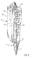
- the support means 1 enable the last A to be supported in an inverted position, that is, with the sole facing upwards, as shown in Figure 1.
- the support means comprise a pad, partially visible in Figure 1, for supporting the toe of the last A, and a rear support which is adjustable in height.
- the insole B is positioned on the sole of the last A and the upper C is stretched over the remaining portion of the last.
- a layer of glue is applied to the surface of the insole B which is to come into contact with the folded edge of the upper C, that is, the upward-facing surface visible in Figure 1, so that the upper C can be glued to the insole simply by exerting a pressure on the edge of the upper C once it has been bent onto the insole B.
- the insoles are preferably formed by punching from sheet material on which a layer of glue has been spread beforehand.
- the tensioning clamps grip and pull the edges of the upper C so as to apply sufficient tension to the upper C to cause it to fit tightly against the last A.
- the means 2 for clamping the last A to the support means 1 take the form of two jaws which can be clamped onto the last A below its sole. This enables the upper C to be kept stretched over the last A even after the edge of the upper C has been released by the tensioning clamps.
- the bending and pressing means 3 take the form of a plurality of stretchers 3' and further closure plates 3" which enable the edge of the upper C to be bent onto the sides 5 and onto the rear portion 4 of the insole B.
- the heel-lasting machine further comprises means 6 for sending hot air towards the portions of the insole B which are covered with glue and which are to come into contact with the bent and pressed edge of the upper C. These means 6 are positioned above the support means 1 and hence above the last A and the insole B associated therewith.
- the hot air softens the glue of the insole so as to bring about optimal gluing.
- the means for sending hot air advantageously comprise one or more nozzles 7 and, in the embodiment shown, comprise two separate air-supply nozzles.
- the nozzles 7 are movable in order to follow the edge of the insole B along the rear portion 4 and the sides 5 thereof.
- actuating means 8 move the nozzles 7 in a manner such that the air jets emerging therefrom are directed along the edges of the insole B.
- each nozzle 7 is associated with an air-heating device 9 comprising a body 11 of thermally conductive material with which heating means 10 are associated and in which a substantially serpentine duct 12 puts an inlet 13 for the air to be heated into fluid communication with an outlet 14 for the heated air.
- the serpentine duct 12 increases the time spent by the air inside the body 11 so that the air can be heated to a greater extent.
- the nozzle 7 is fixed to the device 9 by means of a threaded connection in the region of the outlet 14 thereof, so as to be in fluid communication with this outlet.
- the body 11 of the device 9 is preferably made of a metallic material such as brass or aluminium.
- the heating means 10 associated with each device 9 take the form of an electrical resistor, the heating of which is regulated by a thermostat (not shown in the drawings) in dependence on the temperature value detected by a heat probe 15 inserted in the body 11.
- the inlet 13 for the air to be heated is connected to a compressed-air distribution network or, in wholly equivalent manner, may be connected to a compressed-air container or to an air blower.
- the actuating means 8 comprise a plurality of linear actuators such as, for example, pneumatic cylinders of known type, not shown in the drawings, which enable the two air-heating devices 9, and hence the respective nozzles 7, to be moved in order to direct the air-flow emerging from each nozzle to the desired point.
- linear actuators such as, for example, pneumatic cylinders of known type, not shown in the drawings, which enable the two air-heating devices 9, and hence the respective nozzles 7, to be moved in order to direct the air-flow emerging from each nozzle to the desired point.
- the two air-heating devices 9 are mounted on a movable framework 16 which is moved by the linear actuators away from and towards the last A along a vertical axis Z-Z and longitudinally relative to the last A along a longitudinal axis X-X.
- the two devices 9 can also be moved relative to the movable framework 16, independently of one another, along an axis Y-Y transverse the axis X-X.
- the heel-lasting machine further comprises an electronic control unit for controlling the operation of the actuating means 8.
- the last A over which an upper C has been stretched beforehand and with which an insole B covered with glue is associated, is positioned on the support means 1 in the manner specified above.
- the tensioning clamps then release the edges of the upper C and are brought to a retracted position. As explained above, the jaws 2 keep the upper stretched over the last A.
- the actuator means 8 move the movable framework 16 towards the last A along the vertical axis Z-Z until the nozzles 7 are in the vicinity of the insole B.
- the two nozzles 7 are then moved by coordinated movement of the framework 16 along the longitudinal axis X-X and of the devices 9 along the transverse axis Y-Y, so that each nozzle follows a portion of the edge of the insole B.
- the nozzles When there are two nozzles arranged symmetrically with respect to the longitudinal axis X-X of the insole B as shown in Figure 1, the nozzles are moved in a manner such that each has to follow one side 5 and one half of the rear portion 5 of the insole B.
- the two nozzles 7 perform reflectively symmetrical movements relative to the longitudinal axis X-X.
- the movable framework 16 is then returned along the axis Z-Z to its initial position in which it is spaced from the last A so as to leave room for the means 3 for bending and pressing the edge of the upper C onto the insole B in the region of the rear portion 4 and of the sides 5 of the insole B.
- the presence of the electronic control unit permits the storage of a different program for controlling the actuating means, that is the actuators, for each type of insole.
- actuating means that is the actuators
- the heel-lasting machine according to the invention satisfies the need referred to in the introduction to the present description and at the same time overcomes the problems of the prior art.
- a further advantage of the heel-lasting machine according to the invention lies in the fact that it is structurally and functionally simple.
Landscapes
- Footwear And Its Accessory, Manufacturing Method And Apparatuses (AREA)
- Compressors, Vaccum Pumps And Other Relevant Systems (AREA)
- Seeds, Soups, And Other Foods (AREA)
Claims (12)
- Vorrichtung zum Zwicken im Fersenbereich für die Herstellung von Schuhzeug mit
Haltemitteln (1), um darauf einen Leisten (A) anzuordnen, über den ein Obermaterial (C) gezogen wird und dem eine klebstoffbedeckte Brandsohle (B) zugeordnet ist, einer Mehrzahl von Spannklammern, um an der Kannte des Obermaterials (C) anzugreifen und das Obermaterial (C) zu ziehen, um es in enge Passung an den Leisten (A) zu bringen, Mitteln (2) zum Klammern des Leisten (A) an die Haltemittel (1), Mittel (3) zum Biegen und Pressen der Kannte des Obermaterials (C) auf die Brandsohle (B) im Bereich des hinteren Abschnitts (4) und der Seiten (5) der Brandsohle (B) und Mitteln (6), um heiße Luft zu den Abschnitten der Brandsohle (B) zu leiten, die mit Klebstoff bedeckt sind und die mit der gefalteten und gepressten Kante des Obermaterials (C) in Kontakt kommen, wobei die Mittel (6) zum Zuleiten der heißen Luft eine Luftzuführdüse (7) aufweisen, die bewegt werden kann, um der Kannte der Brandsohle (B) entlang des hinteren Abschnitts (4) und deren Seiten (5) zu folgen, wobei die Vorrichtung Betätigungsmittel aufweist, um zu einer solchen Bewegung der Düse (7) zu führen, dass die Düse (7) den Luftstrahl entlang der Kannten der Brandsohle (B) richtet,
dadurch gekennzeichnet, dass die Mittel (3) zum Biegen und Pressen der Kannte des Obermaterials (C) dafür vorgesehen sind zu arbeiten, nachdem die vollständige thermische Erweichung des Klebstoffs entlang des hinteren Abschnitts (4) und der Seiten (5) der Brandsohle (B) durchgeführt worden ist. - Vorrichtung nach Anspruch 1 mit einer Luftheizvorrichtung (9), die ein Gehäuse (11) aus Wärme leitendem Material aufweist, dem Heizmittel (10) zugeordnet sind und in dem eine im wesentlichen schlangenförmige Leitung (12) einen Einlass (13) für die zu heizende Luft in Strömungsverbindung mit einem Auslass (14) bringt, wobei die Düse (7) mit dem Auslass (14) verbunden ist.
- Vorrichtung nach Anspruch 2, bei dem ein Wärmefühler (15) mit der Luftheizvorrichtung (9) verbunden ist, um die Temperatur zu erfassen.
- Vorrichtung nach Anspruch 2, bei dem die Heizmittel (11) einen elektrischen Widerstand aufweisen.
- Vorrichtung nach Anspruch 3 oder 4 mit einem Temperaturregler für die Steuerung der Heizung des elektrischen Widerstands abhängig von dem durch den Wärmefühler (15) erfassten Temperaturwert.
- Vorrichtung nach Anspruch 2, bei dem das Gehäuse (11) der Luftheizvorrichtung (9) aus einem Wärme leitenden Material gefertigt ist.
- Vorrichtung nach Anspruch 2 oder Anspruch 6, bei dem das Gehäuse (11) der Luftheizvorrichtung (9) aus Metall gefertigt ist.
- Vorrichtung nach Anspruch 2 oder Anspruch 6, bei dem das Gehäuse (11) der Luftheizvorrichtung (9) aus Messing gefertigt ist.
- Vorrichtung nach Anspruch 2, bei dem der Einlass der Luftheizvorrichtung (9) mit einem Pressluftverteilungsnetz verbunden ist.
- Vorrichtung nach Anspruch 1 mit einer elektronischen Steuereinheit für die Steuerung der Arbeit der Betätigungsmittel, wobei für jede Art von Brandsohle (B) ein anderes Programm für die Steuerung der Bestätigungsmittel der Düse (7) in der Steuerungseinheit gespeichert ist.
- Vorrichtung nach Anspruch 1, bei der die Düse (7) zu der Brandsohle (B) gerichtet ist und durch die Betätigungsmittel gehalten wird.
- Vorrichtung nach einem der vorhergehenden Ansprüche mit einer Mehrzahl von unabhängigen Düsen (7), von denen jede dafür vorgesehen ist, einem anderen Abschnitt der Kante der Brandsohle (B) zu folgen.
Applications Claiming Priority (2)
| Application Number | Priority Date | Filing Date | Title |
|---|---|---|---|
| ITMI981527 | 1998-07-02 | ||
| IT98MI001527A ITMI981527A1 (it) | 1998-07-02 | 1998-07-02 | Macchina montaboette per la lavorazione di calzature |
Publications (2)
| Publication Number | Publication Date |
|---|---|
| EP0970631A1 EP0970631A1 (de) | 2000-01-12 |
| EP0970631B1 true EP0970631B1 (de) | 2005-06-15 |
Family
ID=11380372
Family Applications (1)
| Application Number | Title | Priority Date | Filing Date |
|---|---|---|---|
| EP99202129A Expired - Lifetime EP0970631B1 (de) | 1998-07-02 | 1999-07-01 | Maschine zum Zwicken von Schuhen im Fersenbereich |
Country Status (5)
| Country | Link |
|---|---|
| EP (1) | EP0970631B1 (de) |
| AT (1) | ATE297669T1 (de) |
| DE (1) | DE69925785D1 (de) |
| IT (1) | ITMI981527A1 (de) |
| PT (1) | PT970631E (de) |
Families Citing this family (4)
| Publication number | Priority date | Publication date | Assignee | Title |
|---|---|---|---|---|
| ES2353422B1 (es) * | 2008-07-01 | 2012-01-25 | Celtecnia, S.L. | Sistema automatico e independiente para el control de la temperatura de diversas superficies, que incluye una cabeza de secado y/o una campana de reactivacion y un procedimiento para la gestion del sistema. |
| CN112493630B (zh) * | 2020-11-16 | 2025-01-28 | 顺德职业技术学院 | 鞋面快速冷却定型方法 |
| CN114098232B (zh) * | 2021-10-29 | 2023-04-11 | 丽荣鞋业(深圳)有限公司 | 铁板烧和换模一体设备 |
| DE102023133488A1 (de) * | 2023-11-30 | 2025-06-05 | Adidas Ag | Heizmittel, Vorrichtung und Verfahren zum Herstellen eines Schuhwerks |
Family Cites Families (5)
| Publication number | Priority date | Publication date | Assignee | Title |
|---|---|---|---|---|
| US2474307A (en) * | 1945-10-19 | 1949-06-28 | United Shoe Machinery Corp | Lasting machine |
| US2669735A (en) * | 1950-04-14 | 1954-02-23 | United Shoe Machinery Corp | Apparatus for attaching soles to shoes |
| GB793774A (en) * | 1954-01-29 | 1958-04-23 | Clark Ltd C & J | Improvements relating to the manufacture of footwear |
| US4380524A (en) * | 1979-04-06 | 1983-04-19 | International Shoe Machine Corporation | Cement applying machine and method |
| IT1200390B (it) * | 1985-02-26 | 1989-01-18 | Molina & Bianchi Spa | Metodo per incollare al sottopiede di un semilavorato di calzatura i fianchi della relativa tomaia e macchina montafianchi per l'applicazione di tale metodo |
-
1998
- 1998-07-02 IT IT98MI001527A patent/ITMI981527A1/it unknown
-
1999
- 1999-07-01 AT AT99202129T patent/ATE297669T1/de not_active IP Right Cessation
- 1999-07-01 PT PT99202129T patent/PT970631E/pt unknown
- 1999-07-01 EP EP99202129A patent/EP0970631B1/de not_active Expired - Lifetime
- 1999-07-01 DE DE69925785T patent/DE69925785D1/de not_active Expired - Fee Related
Also Published As
| Publication number | Publication date |
|---|---|
| ITMI981527A1 (it) | 2000-01-02 |
| PT970631E (pt) | 2005-08-31 |
| DE69925785D1 (de) | 2005-07-21 |
| EP0970631A1 (de) | 2000-01-12 |
| ATE297669T1 (de) | 2005-07-15 |
Similar Documents
| Publication | Publication Date | Title |
|---|---|---|
| EP0970631B1 (de) | Maschine zum Zwicken von Schuhen im Fersenbereich | |
| US20180153265A1 (en) | Method of manfacturing a fully formed upper | |
| US4266312A (en) | Apparatus for use in laminating a workpiece | |
| US4057179A (en) | Garment pressing machines | |
| EP0328923A2 (de) | Trocknung einer Schicht eines lösungsmittelbasierten Leimes | |
| CN100399959C (zh) | 把胶合剂施加到鞋的内底上的方法 | |
| JPH0213402A (ja) | ヒールくせつけ機 | |
| EP0299748A1 (de) | Plättmaschine für Hemden | |
| CN210581272U (zh) | 一种鞋面软化入楦绑带一体机 | |
| EP1036516B1 (de) | Maschine zur Herstellung von Schuhe | |
| US2549981A (en) | Double activation with conditioning for sole attaching | |
| US4517697A (en) | Adhesive applicator | |
| US3094726A (en) | Apparatus for preparing a shoe for lasting | |
| US3115651A (en) | Method and apparatus for heating shoe stiffeners | |
| EP1498042B1 (de) | Maschine zur Herstellung von Schuhwerken | |
| US4223815A (en) | Post form stay inserter for shirt collars | |
| KR20110063317A (ko) | 수성 접착제를 사용한 신발 측면 조립용 기계 | |
| US2474307A (en) | Lasting machine | |
| US3594839A (en) | Shoe lasting machines | |
| US4593423A (en) | Lasting heel seat and side portions of a shoe | |
| CN212414952U (zh) | 具有冷冻及热风活化模块的后踵定型机 | |
| US3906568A (en) | Band wiping mechanism for shoe lasting machine | |
| US1902848A (en) | Covering breasts of heels | |
| US2963719A (en) | Machines for shaping stitchdown uppers over lasts | |
| RU2014791C1 (ru) | Способ формирования задника заготовки верха обуви |
Legal Events
| Date | Code | Title | Description |
|---|---|---|---|
| PUAI | Public reference made under article 153(3) epc to a published international application that has entered the european phase |
Free format text: ORIGINAL CODE: 0009012 |
|
| AK | Designated contracting states |
Kind code of ref document: A1 Designated state(s): AT BE CH DE ES FR GB GR IT LI PT |
|
| AX | Request for extension of the european patent |
Free format text: AL;LT;LV;MK;RO;SI |
|
| 17P | Request for examination filed |
Effective date: 20000710 |
|
| AKX | Designation fees paid |
Free format text: AT BE CH DE ES FR GB GR IT LI PT |
|
| 17Q | First examination report despatched |
Effective date: 20020704 |
|
| GRAP | Despatch of communication of intention to grant a patent |
Free format text: ORIGINAL CODE: EPIDOSNIGR1 |
|
| GRAS | Grant fee paid |
Free format text: ORIGINAL CODE: EPIDOSNIGR3 |
|
| GRAA | (expected) grant |
Free format text: ORIGINAL CODE: 0009210 |
|
| PGFP | Annual fee paid to national office [announced via postgrant information from national office to epo] |
Ref country code: FR Payment date: 20050614 Year of fee payment: 7 |
|
| AK | Designated contracting states |
Kind code of ref document: B1 Designated state(s): AT BE CH DE ES FR GB GR IT LI PT |
|
| PG25 | Lapsed in a contracting state [announced via postgrant information from national office to epo] |
Ref country code: LI Free format text: LAPSE BECAUSE OF FAILURE TO SUBMIT A TRANSLATION OF THE DESCRIPTION OR TO PAY THE FEE WITHIN THE PRESCRIBED TIME-LIMIT Effective date: 20050615 Ref country code: CH Free format text: LAPSE BECAUSE OF FAILURE TO SUBMIT A TRANSLATION OF THE DESCRIPTION OR TO PAY THE FEE WITHIN THE PRESCRIBED TIME-LIMIT Effective date: 20050615 Ref country code: BE Free format text: LAPSE BECAUSE OF FAILURE TO SUBMIT A TRANSLATION OF THE DESCRIPTION OR TO PAY THE FEE WITHIN THE PRESCRIBED TIME-LIMIT Effective date: 20050615 Ref country code: AT Free format text: LAPSE BECAUSE OF FAILURE TO SUBMIT A TRANSLATION OF THE DESCRIPTION OR TO PAY THE FEE WITHIN THE PRESCRIBED TIME-LIMIT Effective date: 20050615 |
|
| REG | Reference to a national code |
Ref country code: GB Ref legal event code: FG4D Ref country code: CH Ref legal event code: EP |
|
| PGFP | Annual fee paid to national office [announced via postgrant information from national office to epo] |
Ref country code: PT Payment date: 20050713 Year of fee payment: 7 |
|
| REF | Corresponds to: |
Ref document number: 69925785 Country of ref document: DE Date of ref document: 20050721 Kind code of ref document: P |
|
| REG | Reference to a national code |
Ref country code: PT Ref legal event code: SC4A Effective date: 20050624 |
|
| PG25 | Lapsed in a contracting state [announced via postgrant information from national office to epo] |
Ref country code: GR Free format text: LAPSE BECAUSE OF FAILURE TO SUBMIT A TRANSLATION OF THE DESCRIPTION OR TO PAY THE FEE WITHIN THE PRESCRIBED TIME-LIMIT Effective date: 20050915 Ref country code: GB Free format text: LAPSE BECAUSE OF NON-PAYMENT OF DUE FEES Effective date: 20050915 |
|
| PG25 | Lapsed in a contracting state [announced via postgrant information from national office to epo] |
Ref country code: ES Free format text: LAPSE BECAUSE OF FAILURE TO SUBMIT A TRANSLATION OF THE DESCRIPTION OR TO PAY THE FEE WITHIN THE PRESCRIBED TIME-LIMIT Effective date: 20050926 |
|
| REG | Reference to a national code |
Ref country code: CH Ref legal event code: PL |
|
| PG25 | Lapsed in a contracting state [announced via postgrant information from national office to epo] |
Ref country code: DE Free format text: LAPSE BECAUSE OF NON-PAYMENT OF DUE FEES Effective date: 20060201 |
|
| ET | Fr: translation filed | ||
| PLBE | No opposition filed within time limit |
Free format text: ORIGINAL CODE: 0009261 |
|
| STAA | Information on the status of an ep patent application or granted ep patent |
Free format text: STATUS: NO OPPOSITION FILED WITHIN TIME LIMIT |
|
| GBPC | Gb: european patent ceased through non-payment of renewal fee |
Effective date: 20050915 |
|
| 26N | No opposition filed |
Effective date: 20060316 |
|
| PG25 | Lapsed in a contracting state [announced via postgrant information from national office to epo] |
Ref country code: PT Free format text: LAPSE BECAUSE OF NON-PAYMENT OF DUE FEES Effective date: 20070102 |
|
| REG | Reference to a national code |
Ref country code: PT Ref legal event code: MM4A Free format text: LAPSE DUE TO NON-PAYMENT OF FEES Effective date: 20070102 |
|
| REG | Reference to a national code |
Ref country code: FR Ref legal event code: ST Effective date: 20070330 |
|
| PG25 | Lapsed in a contracting state [announced via postgrant information from national office to epo] |
Ref country code: FR Free format text: LAPSE BECAUSE OF NON-PAYMENT OF DUE FEES Effective date: 20060731 |
|
| PGFP | Annual fee paid to national office [announced via postgrant information from national office to epo] |
Ref country code: IT Payment date: 20110712 Year of fee payment: 13 |
|
| PG25 | Lapsed in a contracting state [announced via postgrant information from national office to epo] |
Ref country code: IT Free format text: LAPSE BECAUSE OF NON-PAYMENT OF DUE FEES Effective date: 20120701 |