EP0970763A2 - Vorrichtung zum Herstellen eines Wellrohres durch schraubenlinienförmiges Wickeln eines dünnen gewellten Bandes - Google Patents
Vorrichtung zum Herstellen eines Wellrohres durch schraubenlinienförmiges Wickeln eines dünnen gewellten Bandes Download PDFInfo
- Publication number
- EP0970763A2 EP0970763A2 EP99112526A EP99112526A EP0970763A2 EP 0970763 A2 EP0970763 A2 EP 0970763A2 EP 99112526 A EP99112526 A EP 99112526A EP 99112526 A EP99112526 A EP 99112526A EP 0970763 A2 EP0970763 A2 EP 0970763A2
- Authority
- EP
- European Patent Office
- Prior art keywords
- wave
- tape
- strip
- roller
- shaft
- Prior art date
- Legal status (The legal status is an assumption and is not a legal conclusion. Google has not performed a legal analysis and makes no representation as to the accuracy of the status listed.)
- Granted
Links
Images


Classifications
-
- B—PERFORMING OPERATIONS; TRANSPORTING
- B21—MECHANICAL METAL-WORKING WITHOUT ESSENTIALLY REMOVING MATERIAL; PUNCHING METAL
- B21C—MANUFACTURE OF METAL SHEETS, WIRE, RODS, TUBES, PROFILES OR LIKE SEMI-MANUFACTURED PRODUCTS OTHERWISE THAN BY ROLLING; AUXILIARY OPERATIONS USED IN CONNECTION WITH METAL-WORKING WITHOUT ESSENTIALLY REMOVING MATERIAL
- B21C37/00—Manufacture of metal sheets, rods, wire, tubes, profiles or like semi-manufactured products, not otherwise provided for; Manufacture of tubes of special shape
- B21C37/06—Manufacture of metal sheets, rods, wire, tubes, profiles or like semi-manufactured products, not otherwise provided for; Manufacture of tubes of special shape of tubes or metal hoses; Combined procedures for making tubes, e.g. for making multi-wall tubes
- B21C37/12—Making tubes or metal hoses with helically arranged seams
- B21C37/124—Making tubes or metal hoses with helically arranged seams the tubes having a special shape, e.g. with corrugated wall, flexible tubes
Definitions
- the invention relates to a device for producing a Corrugated tube by helically winding a thin one corrugated band, the waves of which run in the longitudinal direction of the band, at least one wave of the incoming band into one Shaft of the previously generated tape roll is inserted and in which one of the nested waves is deformed, consisting of a winding device from circular on Outer circumference of the support rollers arranged to be wound, from an inner and an outer, at the entry point of the Band arranged in the winding device, on the broad sides attacking the tape, inserting the incoming tape into the previously generated tape wrap and the mutual Connection and deformation of the one causing a shaft Connecting rollers, from a distance in front of the connecting rollers arranged drive roller pair, from a between Connecting rollers and drive rollers arranged tape guide and from a arranged between the tape guide and connecting rollers Bending roll.
- Such generic devices are, for example, from German Patent 3,022,575.3, European Patent 0 182 001 or German patent 35 40 125.
- the individual To connect the windings of the tape winding together for example by depressing in places, by omega-shaped Deform a rotating shaft or the like more, the type of connection according to the Intended use of the corrugated pipe and the starting strip material can be different.
- corrugated pipes produced in this way can be produced after Transport be compressed so that their length is clear is reduced. So compressed at the place of use Corrugated pipes are pulled apart again.
- the press shoulders each advantageously have an outer, the Press shoulder protruding, the trough of the connecting roller adjacent wave tip.
- the wave tip preferably protrudes approximately to the middle of the wave.
- the press shoulder has an advantage Wave tip about half the wave width.
- the press shoulder is curved in the adjacent one Wavy crest of the connecting roller formed continuously.
- the press shoulder is advantageously curved into the shaft tip temporarily trained.
- the bending roller has such a wave profile that the width of the waves to be connected and deformed is halved.
- the band guide preferably has interacting with one another Pairs of rollers.
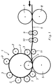
- FIG. 1 to 3 there is a device for manufacturing of a corrugated tube by helically winding one thin corrugated tape, preferably a metal tape, the Waves run in the longitudinal direction of the tape, with at least one Wave of the incoming band into a wave of the preceding generated tape reel is inserted and one of the interlaced waves is deformed from a Winding device 1 from circular on the outer circumference winding tube 2 arranged support rollers 3 (Fig. 1) and out an inner connecting roller 4 and an outer Connecting roller 5.
- the inner and outer connecting roller 4 and 5 are at the entry point of a corrugated belt 6 in the Winding device 1 arranged, the inner Connection roller 4 is arranged within the winding device and the outer connecting roller 5 with a larger diameter is arranged outside the winding device.
- the Connecting rollers 4 and 5 engage on the broad sides of the belt 6 and cause the insertion of the incoming band 6 in the previously generated tape roll 2 and also the mutual connection and deformation of one shaft.
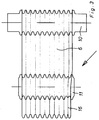
- FIGS. 4 and 5 show, the outer connecting roller 5 one with the wave profile of the incoming band 6 matching wave profile.
- the inner connecting roller 4 has however, a slightly higher wave profile (larger amplitude) than that incoming tape 6.
- Figures 4 and 5 further show that the Corrugated valleys 12 assigned to the outer connecting roller 5 Waves 13 of the inner connecting roller 4 the same Have radius of curvature like that of the incoming band 6. It is the thickness of the lying between the connecting rollers 4 and 5 Volume 6 and the tape winding taken into account.
- the assigned to the wave crests 14 of the outer connecting roller 5 Troughs 15 of the inner connecting roller 4 a little larger radius of curvature than that of the incoming tape.
- Figures 4 and 5 further show that the inner and outer Connecting roller 4 and 5 in the area to be connected and deforming shaft 16 each approximately below the shaft center (below half the amplitude) diametrically opposite each other opposite, an approximately square deformation space 17th have forming press shoulders 18.
- the press shoulders 18 have each an outer, the press shoulder protruding, the Trough 12, 15 of the respective connecting roller 5, 4 adjacent Wave tip 19, which approximately to the middle of the wave (half amplitude) protrudes.
- the press shoulders 18 go curved in the neighboring Wellenberg 14, 13 over.
- the deformation space 17 thus formed is roughly square. Its side length corresponds approximately to one half wave width of a wave crest and a wave trough.
- the bending roller 11 Wave width of the wave 16 to be connected and deformed tapered band 6 approximately halved and so the connecting rollers 4th and 5 fed. This is possible because of the higher position the bending roller 1 and the tension of the belt 6 between the Connection rollers 4 and 5 and the drive rollers 7 and 8 a appropriate force can be exerted on the tape.
- the approaching Band 6 exactly in the profile identical to the profile of the band the outer connecting roller 5 inserted.
- the higher (larger amplitude) and slimmer profile of the inner Connecting roller 4 then press the crests 13 of the inner Connection roller 4 the incoming band 6 firmly in the troughs 12 of the outer connecting roller 5, so that the incoming tape over the entire profile in the previously generated Tape wrap lies. This results in one over the entire profile uniform and firm contact of the superimposed ones Windings.
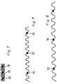
- the deformed Wave 16 in the middle between Wellenberg and Wellental (half Amplitude). 7 shows, when compressing the Corrugated pipe to about a third of its production length Fig. 6 put the wave edges together.
- the deformed shaft 16 in the middle between Wellenberg and This results in a symmetrical and even wave trough Loading the waves.
- the Wave tips 19 cause a predetermined bending point, so that the deformed shaft 16 is loaded little or not at all.
Landscapes
- Engineering & Computer Science (AREA)
- Mechanical Engineering (AREA)
- Shaping Of Tube Ends By Bending Or Straightening (AREA)
- Rigid Pipes And Flexible Pipes (AREA)
- Catalysts (AREA)
- Making Paper Articles (AREA)
- Manufacturing Of Electric Cables (AREA)
Abstract
Description
- Fig. 1
- eine erfindungsgemäße Vorrichtung in schematischer Seitenansicht,
- Fig. 2
- einen Teil der Vorrichtung nach Fig. 1 in Draufsicht mit einen zulaufenden Band,
- Fig. 3
- ein Detail der Vorrichtung nach Fig. 2 in Draufsicht,
- Fig. 4
- einen Schnitt durch die Verbindungsrollen ohne Band bzw. ohne Wellenrohr,
- Fig. 5
- einen Schnitt durch die Verbindungsrollen entsprechend Fig. 4 mit einem Band bzw. Wellrohr,
- Fig. 6
- einen teilweisen Schnitt durch ein Wellrohr mit Herstellungslänge,
- Fig. 7
- einen teilweisen Schnitt durch ein gestauchtes Wellrohr und
- Fig. 8
- einen teilweisen Schnitt durch ein gedehntes Wellrohr.
Claims (8)
- Vorrichtung zum Herstellen eines Wellrohres durch schraubenlinienförmiges Wickeln eines dünnen gewellten Bandes, dessen Wellen in Bandlängsrichtung verlaufen, bei der mindestens eine Welle des zulaufenden Bandes in eine Welle des vorausgehend erzeugten Bandwickels eingelegt wird und bei der eine der ineinandergelegten Wellen verformt wird, bestehend aus einer Wickeleinrichtung aus kreisförmig am Außenumfang des zu wickelnden Rohres angeordneten Stützrollen, aus einer inneren und einer äußeren, an der Einlaufstelle des Bandes in die Wickeleinrichtung angeordneten, an den Breitseiten des Bandes angreifenden, das Einlegen des zulaufenden Bandes in den vorausgehend erzeugten Bandwickel und die gegenseitige Verbindung und Verformung der einen Welle bewirkenden Verbindungsrollen, aus einem im Abstand vor den Verbindungsrollen angeordneten Antriebsrollenpaar, aus einer zwischen Verbindungsrollen und Antriebsrollen angeordneten Bandführung und aus einer zwischen Bandführung und Verbindungsrollen angeordneten Biegerolle, dadurch gekennzeichnet, daß die äußere Verbindungsrolle (5) ein mit dem Wellenprofil des zulaufenden Bandes (6) übereinstimmendes Wellenprofil hat, daß die innere Verbindungsrolle (4) ein etwas höheres Wellenprofil als das zulaufende Band hat, dessen den Wellentälern (12) der äußeren Verbindungsrolle (5) zugeordneten Wellenberge (13) den gleichen Krümmungsradius wie der des zulaufenden Bandes haben und dessen den Wellenbergen (14) der äußeren Verbindungsrolle (5) zugeordneten Wellentäler (15) einen etwas größeren Krümmungsradius als der des zulaufenden Bandes haben, und daß die innere und die äußere Verbindungsrolle im Bereich der zu verbindenden und zu verformenden Welle (16) jeweils etwas unterhalb der Wellenmitte, einander diametral gegenüberliegende, einen etwa quadratischen Verformungsraum (17) bildende Preßschultern (18) haben.
- Vorrichtung nach Anspruch 1, dadurch gekennzeichnet, daß die Preßschultern (18) jeweils eine äußere, die Preßschulter überragende, dem Wellental der Verbindungsrolle (12, 15) benachbarte Wellenspitze (19) haben.
- Vorrichtung nach Anspruch 2, dadurch gekennzeichnet, daß die Wellenspitze (19) etwa bis zur Wellenmitte ragt.
- Vorrichtung nach einem der Ansprüche 1 bis 3, dadurch gekennzeichnet, daß die Preßschulter (18) mit Wellenspitze (19) etwa halbe Wellenbreite hat.
- Vorrichtung nach einem der Ansprüche 1 bis 4, dadurch gekennzeichnet, daß die Preßschulter (18) gekrümmt in den benachbarten Wellenberg (14, 13) der Verbindungsrolle (5, 4) übergehend ausgebildet ist.
- Vorrichtung nach einem der Ansprüche 1 bis 5, dadurch gekennzeichnet, daß die Preßschulter (18) gekrümmt in die Wellenspitze (19) übergehend ausgebildet ist.
- Vorrichtung nach einem der Ansprüche 1 bis 6, dadurch gekennzeichnet, daß die Biegerolle (11) ein derartiges Wellenprofil hat, daß die Breite der zu verbindenden und zu verformenden Welle (16) halbiert ist.
- Vorrichtung nach einem der Ansprüche 1 bis 7, dadurch gekennzeichnet, daß die Bandführung miteinander zusammenwirkende Rollenpaare (9, 10) hat.
Applications Claiming Priority (2)
| Application Number | Priority Date | Filing Date | Title |
|---|---|---|---|
| DE19830401A DE19830401C1 (de) | 1998-07-08 | 1998-07-08 | Vorrichtung zum Herstellen eines Wellrohres durch schraubenlinienförmiges Wickeln eines dünnen gewellten Bandes |
| DE19830401 | 1998-07-08 |
Publications (3)
| Publication Number | Publication Date |
|---|---|
| EP0970763A2 true EP0970763A2 (de) | 2000-01-12 |
| EP0970763A3 EP0970763A3 (de) | 2001-05-09 |
| EP0970763B1 EP0970763B1 (de) | 2003-04-02 |
Family
ID=7873272
Family Applications (1)
| Application Number | Title | Priority Date | Filing Date |
|---|---|---|---|
| EP99112526A Expired - Lifetime EP0970763B1 (de) | 1998-07-08 | 1999-07-01 | Vorrichtung zum Herstellen eines Wellrohres durch schraubenlinienförmiges Wickeln eines dünnen gewellten Bandes |
Country Status (5)
| Country | Link |
|---|---|
| EP (1) | EP0970763B1 (de) |
| AT (1) | ATE235973T1 (de) |
| DE (2) | DE19830401C1 (de) |
| ES (1) | ES2194404T3 (de) |
| PT (1) | PT970763E (de) |
Families Citing this family (2)
| Publication number | Priority date | Publication date | Assignee | Title |
|---|---|---|---|---|
| DE102013013735B4 (de) | 2013-08-21 | 2018-12-27 | Fritz Hahn Gmbh & Co. Kg | Vorrichtung und Verfahren zur Herstellung eines Wickelfalzrohres sowie ein mit der Vorrichtung und nach dem Verfahren aus einem profilierten Metallband hergestelltes Wickelfalzrohr |
| CN106180328A (zh) * | 2016-07-20 | 2016-12-07 | 江苏龙胜机床制造有限公司 | 一种环形金属波纹管成型机床 |
Citations (3)
| Publication number | Priority date | Publication date | Assignee | Title |
|---|---|---|---|---|
| DE3022575A1 (de) | 1980-06-16 | 1981-12-24 | Fritz Hahn Kg, 5500 Trier | Vorrichtung zum herstellen von rohren durch schraubenlinienfoermiges wickeln eines vorzugsweise gewellten bandes |
| EP0182001A2 (de) | 1984-11-14 | 1986-05-28 | Fritz Hahn GmbH & Co. KG | Verfahren und Vorrichtung zum Herstellen eines flexiblen Wellrohres sowie nach dem Verfahren hergestelltes flexibles Wellrohr |
| DE3540125A1 (de) | 1985-11-13 | 1987-05-14 | Hahn Fritz Kg | Verfahren und vorrichtung zum herstellen eines wellrohres durch schraubenlinienfoermiges wickeln eines gewellten, duennen bandes, vorzugsweise eines stahlbandes |
Family Cites Families (1)
| Publication number | Priority date | Publication date | Assignee | Title |
|---|---|---|---|---|
| US3863480A (en) * | 1973-08-28 | 1975-02-04 | Johns Manville | Apparatus for forming corrugated strip material into helically wound tubing |
-
1998
- 1998-07-08 DE DE19830401A patent/DE19830401C1/de not_active Expired - Fee Related
-
1999
- 1999-07-01 DE DE59904810T patent/DE59904810D1/de not_active Expired - Lifetime
- 1999-07-01 EP EP99112526A patent/EP0970763B1/de not_active Expired - Lifetime
- 1999-07-01 ES ES99112526T patent/ES2194404T3/es not_active Expired - Lifetime
- 1999-07-01 PT PT99112526T patent/PT970763E/pt unknown
- 1999-07-01 AT AT99112526T patent/ATE235973T1/de not_active IP Right Cessation
Patent Citations (3)
| Publication number | Priority date | Publication date | Assignee | Title |
|---|---|---|---|---|
| DE3022575A1 (de) | 1980-06-16 | 1981-12-24 | Fritz Hahn Kg, 5500 Trier | Vorrichtung zum herstellen von rohren durch schraubenlinienfoermiges wickeln eines vorzugsweise gewellten bandes |
| EP0182001A2 (de) | 1984-11-14 | 1986-05-28 | Fritz Hahn GmbH & Co. KG | Verfahren und Vorrichtung zum Herstellen eines flexiblen Wellrohres sowie nach dem Verfahren hergestelltes flexibles Wellrohr |
| DE3540125A1 (de) | 1985-11-13 | 1987-05-14 | Hahn Fritz Kg | Verfahren und vorrichtung zum herstellen eines wellrohres durch schraubenlinienfoermiges wickeln eines gewellten, duennen bandes, vorzugsweise eines stahlbandes |
Also Published As
| Publication number | Publication date |
|---|---|
| ATE235973T1 (de) | 2003-04-15 |
| DE19830401C1 (de) | 1999-10-14 |
| PT970763E (pt) | 2003-08-29 |
| EP0970763A3 (de) | 2001-05-09 |
| ES2194404T3 (es) | 2003-11-16 |
| EP0970763B1 (de) | 2003-04-02 |
| DE59904810D1 (de) | 2003-05-08 |
Similar Documents
| Publication | Publication Date | Title |
|---|---|---|
| EP0017722B1 (de) | Siebband aus thermofixierbaren Kunststoffwendeln und Verfahren zu dessen Herstellung | |
| DE2235012A1 (de) | Flexibles wellrohr | |
| DE2441395A1 (de) | Flexibler zylindrischer metallschlauch und vorrichtung zu dessen herstellung | |
| DE2938221A1 (de) | Siebband aus thermofixierbaren kunststoffwendeln und verfahren zu dessen herstellung | |
| EP1358121B1 (de) | Wickelhülse und verfahren zur herstellung einer wickelhülse | |
| DE2228496C2 (de) | Verfahren zur Wellung eines dünnen, ebenen Bleches | |
| EP0970763B1 (de) | Vorrichtung zum Herstellen eines Wellrohres durch schraubenlinienförmiges Wickeln eines dünnen gewellten Bandes | |
| DE2654963A1 (de) | Flexibles wellrohr | |
| DE19622343A1 (de) | Rollballenpresse mit Abstreiferwalze für landwirtschaftliches Erntegut | |
| DE19507514C2 (de) | Metallene Wickelhülse | |
| DE3016719C2 (de) | ||
| EP0222285B1 (de) | Verfahren und Vorrichtung zum Herstellen eines Wellrohres durch schraubenlinienförmiges Wickeln eines gewellten, dünnen Bandes vorzugsweise eines Stahlbandes | |
| DE102013013735B4 (de) | Vorrichtung und Verfahren zur Herstellung eines Wickelfalzrohres sowie ein mit der Vorrichtung und nach dem Verfahren aus einem profilierten Metallband hergestelltes Wickelfalzrohr | |
| DE4201859C2 (de) | Verfahren und Vorrichtung zum Herstellen eines flexiblen, im Inneren glatten Wellrohres | |
| EP0182001B1 (de) | Verfahren und Vorrichtung zum Herstellen eines flexiblen Wellrohres sowie nach dem Verfahren hergestelltes flexibles Wellrohr | |
| EP1647340B1 (de) | Verfahren zum Herstellen eines flexiblen, im Inneren glatten Wellrohres, sowie ein nach dem Verfahren hergestelltes Wellrohr | |
| DE2660703C2 (de) | Wellrohr für Lüftungsanlagen | |
| DE2602983C2 (de) | Verfahren und Vorrichtung zum Herstellen von Rohren durch schraubenlinienförmiges Aufwickeln eines Bandes | |
| EP0878250A2 (de) | Biegestelle eines dornlos gebogenen dünnwendigen Metallrohres und Vorrichtung zur Herstellung einer solchen Biegestelle | |
| DE7641227U1 (de) | Wickelvorrichtung zur herstellung eines flexiblen wellrohres | |
| DE7221885U (de) | Vorrichtung zum Herstellen eines gewellten dünnen Bleches | |
| DE2453876B2 (de) | Vorrichtung zum herstellen von wickelrohren | |
| DE7226492U (de) | ||
| DE7431953U (de) | Vorrichtung zur Herstellung eines flexiblen Wellrohres |
Legal Events
| Date | Code | Title | Description |
|---|---|---|---|
| PUAI | Public reference made under article 153(3) epc to a published international application that has entered the european phase |
Free format text: ORIGINAL CODE: 0009012 |
|
| AK | Designated contracting states |
Kind code of ref document: A2 Designated state(s): AT BE CH CY DE DK ES FI FR GB GR IE IT LI LU MC NL PT SE |
|
| AX | Request for extension of the european patent |
Free format text: AL;LT PAYMENT 19990726;LV PAYMENT 19990726;MK;RO;SI |
|
| PUAL | Search report despatched |
Free format text: ORIGINAL CODE: 0009013 |
|
| AK | Designated contracting states |
Kind code of ref document: A3 Designated state(s): AT BE CH CY DE DK ES FI FR GB GR IE IT LI LU MC NL PT SE |
|
| AX | Request for extension of the european patent |
Free format text: AL;LT PAYMENT 19990726;LV PAYMENT 19990726;MK;RO;SI |
|
| 17P | Request for examination filed |
Effective date: 20010625 |
|
| AKX | Designation fees paid |
Free format text: AT BE CH CY DE DK ES FI FR GB GR IE IT LI LU MC NL PT SE |
|
| AXX | Extension fees paid |
Free format text: LT PAYMENT 19990726;LV PAYMENT 19990726 |
|
| GRAH | Despatch of communication of intention to grant a patent |
Free format text: ORIGINAL CODE: EPIDOS IGRA |
|
| GRAH | Despatch of communication of intention to grant a patent |
Free format text: ORIGINAL CODE: EPIDOS IGRA |
|
| GRAA | (expected) grant |
Free format text: ORIGINAL CODE: 0009210 |
|
| AK | Designated contracting states |
Designated state(s): AT BE CH CY DE DK ES FI FR GB GR IE IT LI LU MC NL PT SE |
|
| AX | Request for extension of the european patent |
Extension state: LT LV |
|
| PG25 | Lapsed in a contracting state [announced via postgrant information from national office to epo] |
Ref country code: IE Free format text: LAPSE BECAUSE OF NON-PAYMENT OF DUE FEES Effective date: 20030402 Ref country code: FI Free format text: LAPSE BECAUSE OF FAILURE TO SUBMIT A TRANSLATION OF THE DESCRIPTION OR TO PAY THE FEE WITHIN THE PRESCRIBED TIME-LIMIT Effective date: 20030402 |
|
| REG | Reference to a national code |
Ref country code: GB Ref legal event code: FG4D Free format text: NOT ENGLISH |
|
| REG | Reference to a national code |
Ref country code: CH Ref legal event code: EP |
|
| REG | Reference to a national code |
Ref country code: IE Ref legal event code: FG4D Free format text: GERMAN |
|
| REF | Corresponds to: |
Ref document number: 59904810 Country of ref document: DE Date of ref document: 20030508 Kind code of ref document: P |
|
| REG | Reference to a national code |
Ref country code: SE Ref legal event code: TRGR |
|
| PG25 | Lapsed in a contracting state [announced via postgrant information from national office to epo] |
Ref country code: CY Free format text: LAPSE BECAUSE OF FAILURE TO SUBMIT A TRANSLATION OF THE DESCRIPTION OR TO PAY THE FEE WITHIN THE PRESCRIBED TIME-LIMIT Effective date: 20030701 |
|
| PG25 | Lapsed in a contracting state [announced via postgrant information from national office to epo] |
Ref country code: GR Free format text: LAPSE BECAUSE OF FAILURE TO SUBMIT A TRANSLATION OF THE DESCRIPTION OR TO PAY THE FEE WITHIN THE PRESCRIBED TIME-LIMIT Effective date: 20030702 Ref country code: DK Free format text: LAPSE BECAUSE OF FAILURE TO SUBMIT A TRANSLATION OF THE DESCRIPTION OR TO PAY THE FEE WITHIN THE PRESCRIBED TIME-LIMIT Effective date: 20030702 |
|
| GBT | Gb: translation of ep patent filed (gb section 77(6)(a)/1977) | ||
| REG | Reference to a national code |
Ref country code: ES Ref legal event code: FG2A Ref document number: 2194404 Country of ref document: ES Kind code of ref document: T3 |
|
| REG | Reference to a national code |
Ref country code: IE Ref legal event code: FD4D Ref document number: 0970763E Country of ref document: IE |
|
| ET | Fr: translation filed | ||
| PLBE | No opposition filed within time limit |
Free format text: ORIGINAL CODE: 0009261 |
|
| STAA | Information on the status of an ep patent application or granted ep patent |
Free format text: STATUS: NO OPPOSITION FILED WITHIN TIME LIMIT |
|
| 26N | No opposition filed |
Effective date: 20040105 |
|
| PGFP | Annual fee paid to national office [announced via postgrant information from national office to epo] |
Ref country code: MC Payment date: 20090611 Year of fee payment: 11 |
|
| PGFP | Annual fee paid to national office [announced via postgrant information from national office to epo] |
Ref country code: LU Payment date: 20090609 Year of fee payment: 11 Ref country code: FR Payment date: 20090608 Year of fee payment: 11 |
|
| PGFP | Annual fee paid to national office [announced via postgrant information from national office to epo] |
Ref country code: ES Payment date: 20090710 Year of fee payment: 11 Ref country code: CH Payment date: 20090610 Year of fee payment: 11 |
|
| PGFP | Annual fee paid to national office [announced via postgrant information from national office to epo] |
Ref country code: GB Payment date: 20090609 Year of fee payment: 11 Ref country code: AT Payment date: 20090605 Year of fee payment: 11 |
|
| PG25 | Lapsed in a contracting state [announced via postgrant information from national office to epo] |
Ref country code: MC Free format text: LAPSE BECAUSE OF NON-PAYMENT OF DUE FEES Effective date: 20100731 |
|
| REG | Reference to a national code |
Ref country code: CH Ref legal event code: PL |
|
| GBPC | Gb: european patent ceased through non-payment of renewal fee |
Effective date: 20100701 |
|
| REG | Reference to a national code |
Ref country code: FR Ref legal event code: ST Effective date: 20110331 |
|
| PG25 | Lapsed in a contracting state [announced via postgrant information from national office to epo] |
Ref country code: CH Free format text: LAPSE BECAUSE OF NON-PAYMENT OF DUE FEES Effective date: 20100731 Ref country code: LI Free format text: LAPSE BECAUSE OF NON-PAYMENT OF DUE FEES Effective date: 20100731 |
|
| PG25 | Lapsed in a contracting state [announced via postgrant information from national office to epo] |
Ref country code: AT Free format text: LAPSE BECAUSE OF NON-PAYMENT OF DUE FEES Effective date: 20100701 Ref country code: FR Free format text: LAPSE BECAUSE OF NON-PAYMENT OF DUE FEES Effective date: 20100802 |
|
| PG25 | Lapsed in a contracting state [announced via postgrant information from national office to epo] |
Ref country code: GB Free format text: LAPSE BECAUSE OF NON-PAYMENT OF DUE FEES Effective date: 20100701 |
|
| REG | Reference to a national code |
Ref country code: ES Ref legal event code: FD2A Effective date: 20110818 |
|
| PG25 | Lapsed in a contracting state [announced via postgrant information from national office to epo] |
Ref country code: ES Free format text: LAPSE BECAUSE OF NON-PAYMENT OF DUE FEES Effective date: 20100702 |
|
| PG25 | Lapsed in a contracting state [announced via postgrant information from national office to epo] |
Ref country code: LU Free format text: LAPSE BECAUSE OF NON-PAYMENT OF DUE FEES Effective date: 20100701 |
|
| PGFP | Annual fee paid to national office [announced via postgrant information from national office to epo] |
Ref country code: PT Payment date: 20150624 Year of fee payment: 17 |
|
| PGFP | Annual fee paid to national office [announced via postgrant information from national office to epo] |
Ref country code: NL Payment date: 20150723 Year of fee payment: 17 |
|
| PGFP | Annual fee paid to national office [announced via postgrant information from national office to epo] |
Ref country code: BE Payment date: 20150723 Year of fee payment: 17 Ref country code: SE Payment date: 20150724 Year of fee payment: 17 |
|
| PGFP | Annual fee paid to national office [announced via postgrant information from national office to epo] |
Ref country code: IT Payment date: 20150728 Year of fee payment: 17 |
|
| PG25 | Lapsed in a contracting state [announced via postgrant information from national office to epo] |
Ref country code: BE Free format text: LAPSE BECAUSE OF NON-PAYMENT OF DUE FEES Effective date: 20160731 |
|
| REG | Reference to a national code |
Ref country code: LT Ref legal event code: MM9D Effective date: 20160701 |
|
| REG | Reference to a national code |
Ref country code: NL Ref legal event code: MM Effective date: 20160801 |
|
| REG | Reference to a national code |
Ref country code: SE Ref legal event code: EUG |
|
| PG25 | Lapsed in a contracting state [announced via postgrant information from national office to epo] |
Ref country code: NL Free format text: LAPSE BECAUSE OF NON-PAYMENT OF DUE FEES Effective date: 20160801 Ref country code: SE Free format text: LAPSE BECAUSE OF NON-PAYMENT OF DUE FEES Effective date: 20160702 |
|
| PG25 | Lapsed in a contracting state [announced via postgrant information from national office to epo] |
Ref country code: PT Free format text: LAPSE BECAUSE OF NON-PAYMENT OF DUE FEES Effective date: 20170102 |
|
| PG25 | Lapsed in a contracting state [announced via postgrant information from national office to epo] |
Ref country code: IT Free format text: LAPSE BECAUSE OF NON-PAYMENT OF DUE FEES Effective date: 20160701 |
|
| PGFP | Annual fee paid to national office [announced via postgrant information from national office to epo] |
Ref country code: DE Payment date: 20170724 Year of fee payment: 19 |
|
| REG | Reference to a national code |
Ref country code: DE Ref legal event code: R119 Ref document number: 59904810 Country of ref document: DE |
|
| PG25 | Lapsed in a contracting state [announced via postgrant information from national office to epo] |
Ref country code: DE Free format text: LAPSE BECAUSE OF NON-PAYMENT OF DUE FEES Effective date: 20190201 |