EP0970797A2 - Procédé et appareil pour laminer des bandes de caoutchouc non vulcanisé. - Google Patents
Procédé et appareil pour laminer des bandes de caoutchouc non vulcanisé. Download PDFInfo
- Publication number
- EP0970797A2 EP0970797A2 EP99305454A EP99305454A EP0970797A2 EP 0970797 A2 EP0970797 A2 EP 0970797A2 EP 99305454 A EP99305454 A EP 99305454A EP 99305454 A EP99305454 A EP 99305454A EP 0970797 A2 EP0970797 A2 EP 0970797A2
- Authority
- EP
- European Patent Office
- Prior art keywords
- rubber
- rubber material
- extruder
- band
- materials
- Prior art date
- Legal status (The legal status is an assumption and is not a legal conclusion. Google has not performed a legal analysis and makes no representation as to the accuracy of the status listed.)
- Granted
Links
Images



Classifications
-
- B—PERFORMING OPERATIONS; TRANSPORTING
- B29—WORKING OF PLASTICS; WORKING OF SUBSTANCES IN A PLASTIC STATE IN GENERAL
- B29D—PRODUCING PARTICULAR ARTICLES FROM PLASTICS OR FROM SUBSTANCES IN A PLASTIC STATE
- B29D30/00—Producing pneumatic or solid tyres or parts thereof
- B29D30/06—Pneumatic tyres or parts thereof (e.g. produced by casting, moulding, compression moulding, injection moulding, centrifugal casting)
- B29D30/52—Unvulcanised treads, e.g. on used tyres; Retreading
- B29D30/58—Applying bands of rubber treads, i.e. applying camel backs
- B29D30/60—Applying bands of rubber treads, i.e. applying camel backs by winding narrow strips
-
- B—PERFORMING OPERATIONS; TRANSPORTING
- B29—WORKING OF PLASTICS; WORKING OF SUBSTANCES IN A PLASTIC STATE IN GENERAL
- B29C—SHAPING OR JOINING OF PLASTICS; SHAPING OF MATERIAL IN A PLASTIC STATE, NOT OTHERWISE PROVIDED FOR; AFTER-TREATMENT OF THE SHAPED PRODUCTS, e.g. REPAIRING
- B29C48/00—Extrusion moulding, i.e. expressing the moulding material through a die or nozzle which imparts the desired form; Apparatus therefor
- B29C48/16—Articles comprising two or more components, e.g. co-extruded layers
- B29C48/18—Articles comprising two or more components, e.g. co-extruded layers the components being layers
-
- B—PERFORMING OPERATIONS; TRANSPORTING
- B29—WORKING OF PLASTICS; WORKING OF SUBSTANCES IN A PLASTIC STATE IN GENERAL
- B29C—SHAPING OR JOINING OF PLASTICS; SHAPING OF MATERIAL IN A PLASTIC STATE, NOT OTHERWISE PROVIDED FOR; AFTER-TREATMENT OF THE SHAPED PRODUCTS, e.g. REPAIRING
- B29C53/00—Shaping by bending, folding, twisting, straightening or flattening; Apparatus therefor
- B29C53/56—Winding and joining, e.g. winding spirally
- B29C53/58—Winding and joining, e.g. winding spirally helically
- B29C53/581—Winding and joining, e.g. winding spirally helically using sheets or strips consisting principally of plastics material
-
- B—PERFORMING OPERATIONS; TRANSPORTING
- B60—VEHICLES IN GENERAL
- B60C—VEHICLE TYRES; TYRE INFLATION; TYRE CHANGING; CONNECTING VALVES TO INFLATABLE ELASTIC BODIES IN GENERAL; DEVICES OR ARRANGEMENTS RELATED TO TYRES
- B60C1/00—Tyres characterised by the chemical composition or the physical arrangement or mixture of the composition
- B60C1/0008—Compositions of the inner liner
-
- B—PERFORMING OPERATIONS; TRANSPORTING
- B29—WORKING OF PLASTICS; WORKING OF SUBSTANCES IN A PLASTIC STATE IN GENERAL
- B29C—SHAPING OR JOINING OF PLASTICS; SHAPING OF MATERIAL IN A PLASTIC STATE, NOT OTHERWISE PROVIDED FOR; AFTER-TREATMENT OF THE SHAPED PRODUCTS, e.g. REPAIRING
- B29C48/00—Extrusion moulding, i.e. expressing the moulding material through a die or nozzle which imparts the desired form; Apparatus therefor
- B29C48/03—Extrusion moulding, i.e. expressing the moulding material through a die or nozzle which imparts the desired form; Apparatus therefor characterised by the shape of the extruded material at extrusion
- B29C48/07—Flat, e.g. panels
-
- B—PERFORMING OPERATIONS; TRANSPORTING
- B29—WORKING OF PLASTICS; WORKING OF SUBSTANCES IN A PLASTIC STATE IN GENERAL
- B29C—SHAPING OR JOINING OF PLASTICS; SHAPING OF MATERIAL IN A PLASTIC STATE, NOT OTHERWISE PROVIDED FOR; AFTER-TREATMENT OF THE SHAPED PRODUCTS, e.g. REPAIRING
- B29C48/00—Extrusion moulding, i.e. expressing the moulding material through a die or nozzle which imparts the desired form; Apparatus therefor
- B29C48/25—Component parts, details or accessories; Auxiliary operations
- B29C48/285—Feeding the extrusion material to the extruder
- B29C48/288—Feeding the extrusion material to the extruder in solid form, e.g. powder or granules
- B29C48/2886—Feeding the extrusion material to the extruder in solid form, e.g. powder or granules of fillers or of fibrous materials, e.g. short-fibre reinforcements
-
- B—PERFORMING OPERATIONS; TRANSPORTING
- B29—WORKING OF PLASTICS; WORKING OF SUBSTANCES IN A PLASTIC STATE IN GENERAL
- B29C—SHAPING OR JOINING OF PLASTICS; SHAPING OF MATERIAL IN A PLASTIC STATE, NOT OTHERWISE PROVIDED FOR; AFTER-TREATMENT OF THE SHAPED PRODUCTS, e.g. REPAIRING
- B29C48/00—Extrusion moulding, i.e. expressing the moulding material through a die or nozzle which imparts the desired form; Apparatus therefor
- B29C48/25—Component parts, details or accessories; Auxiliary operations
- B29C48/285—Feeding the extrusion material to the extruder
- B29C48/297—Feeding the extrusion material to the extruder at several locations, e.g. using several hoppers or using a separate additive feeding
-
- B—PERFORMING OPERATIONS; TRANSPORTING
- B29—WORKING OF PLASTICS; WORKING OF SUBSTANCES IN A PLASTIC STATE IN GENERAL
- B29K—INDEXING SCHEME ASSOCIATED WITH SUBCLASSES B29B, B29C OR B29D, RELATING TO MOULDING MATERIALS OR TO MATERIALS FOR MOULDS, REINFORCEMENTS, FILLERS OR PREFORMED PARTS, e.g. INSERTS
- B29K2021/00—Use of unspecified rubbers as moulding material
-
- B—PERFORMING OPERATIONS; TRANSPORTING
- B29—WORKING OF PLASTICS; WORKING OF SUBSTANCES IN A PLASTIC STATE IN GENERAL
- B29K—INDEXING SCHEME ASSOCIATED WITH SUBCLASSES B29B, B29C OR B29D, RELATING TO MOULDING MATERIALS OR TO MATERIALS FOR MOULDS, REINFORCEMENTS, FILLERS OR PREFORMED PARTS, e.g. INSERTS
- B29K2105/00—Condition, form or state of moulded material or of the material to be shaped
- B29K2105/24—Condition, form or state of moulded material or of the material to be shaped crosslinked or vulcanised
- B29K2105/246—Uncured, e.g. green
Definitions
- This invention relates to a method and an apparatus for the lamination of band-shaped uncured rubber materials, and more particularly to a method of extruding two or more uncured rubber materials having different moduli (modulus of elasticity) after the curing through an extruder and laminating the extruded band-shaped rubber materials on a rotating support to form a set of rubber members and an apparatus for realizing such a method.
- the invention relates to a method and an apparatus for the lamination of band-shaped uncured rubber members in the building of a pneumatic tire.
- the composite In the production of the composite comprised of various rubbers, a step of laying various uncured rubber members is required prior to the curing of the composite. This is applied when the composite is comprised of various rubbers and various reinforcing materials.
- the composite In pneumatic tires, the composite is comprised of a reinforcing member such as a rubberized cord or the like and various rubber members.
- a green tire formed by laying uncured rubber materials and reinforcing materials such as uncured rubberized cords and the like.
- JP-B-7-94155 proposes a method and an apparatus wherein an outlet orifice of a volumetric extruder is located in the vicinity of a position of arranging rubber material on a rotating support and the rubber material is directly extruded through the outlet orifice of the volumetric extruder onto the rotating support.
- joint face indicating a large modulus difference is existent in a greater part of the tire. Therefore, when the tire is run under loading over a long distance of several ten thousands kilometers, strain repeatedly and concentrically acts to these joint faces over a long time. As a result, troubles such as separation and the like are easily caused in the joint faces to lower the durability.
- each of the rubber composite is made of a rubber composition having a proper plan compromised between both the properties, so that optimum plan of each rubber composite can not be realized at the present.
- JP-B-40-24384 suggests a method of solving such a problem. That is, this publication proposes a method wherein a given portion of a tire is formed while gradually changing from an uncured rubber material to another uncured rubber material when plural different uncured rubber materials are laid on an uncured carcass member.
- an object of the invention to solve the aforementioned problems in the manufacture of the tire and other rubber composite and to provide a method for laminating band-shaped uncured rubber materials in a high productivity capable of establishing the sufficient holding of the durability in the tire or the other rubber composite and the application of optimizedly planed rubber composition to each rubber material and realizing highly precise given sectional shape and arrangement of each rubber material on the premise of space saving and molding automation.
- a method of laminating band-shaped uncured rubber materials to form a laminated rubber member having a given sectional shape by helically winding a band-shaped uncured rubber material extruded through an extruder on a rotating support which comprises using two or more rubber compositions indicating different moduli after the curing as a rubber material fed to the extruder;
- only the second rubber material is successively extruded through the extruder while holding the same extrusion sectional shape and helically wound on the second rubber layer so as to overlap with at least a part of the second rubber layer to form a third rubber layer.
- the second rubber material and a third rubber material are successively extruded through the extruder so as to stepwise or gradually increase a blending ratio of the third rubber material to the second rubber material while holding the same extrusion sectional shape and helically wound on the third rubber layer while overlapping with at least a part of the third rubber layer to form a fourth rubber layer.
- only the third rubber material is successively extruded through the extruder while holding the same extrusion sectional shape and helically wound on the fourth rubber layer so as to overlap with at least a part of the fourth rubber layer to form a fifth rubber layer.
- the rubber material extruded through the extruder as a band-shaped rubber member is helically wound on the rotating support along a rotating axial direction of the support so as to overlap at least widthwise edge portions of the wound rubber members with each other.
- two or more rubber materials have such a property that at least one of 100% modulus and 300% modulus after the curing differs by not less than 1.0 MPa between the two rubber materials to be extruded.
- the first rubber material is at least one of an air-impermeable halogenated butyl rubber composition and butyl rubber composition
- the second rubber material is at least one of a natural rubber composition and a natural rubber based synthetic rubber composition.
- the first rubber material is a rubber composition for a tread under cushion in the cured tire
- the second rubber material is a rubber composition for a tread base
- the third rubber material is a rubber composition for a tread cap.
- the first rubber material is a rubber composition for a bead filler in the cured tire
- the second rubber material is a rubber composition for a sidewall
- the third rubber material is a rubber composition for a rubber chafer.
- an apparatus for laminating band-shaped uncured rubber materials to form a laminated rubber member comprising a rotatable support to be wound on its surface with a band-shaped uncured rubber material, an extruder feeding a band-shaped uncured rubber material to the surface of the support, and two or more rubber material feeding devices individually feeding two or more kinds of rubber materials to the extruder, in which each of the rubber material feeding devices is provided with a feed control means for weighing a weight of a rubber material and adjusting a feeding quantity of a rubber material per unit time.
- the extruder is provided with a control means for controlling feed time and feed stop time of the rubber material weighed through the feed control means to the extruder.
- At least one of the support and the extruder is provided with a moving mechanism capable of relatively moving along a rotating axis of the support.
- the apparatus for laminating band-shaped uncured rubber materials according to the invention comprises a combination of a support 1 and an extruder 2.
- the support 1 is attached to a shaft 1a rotating by a driving source (not shown).
- the support 1 is a forming drum, maintermediate body formed by winding a part of uncured rubber material, uncured rubberized cords and the like on the forming drum, a base tire for retreading and so on.
- a base tire is a tire obtained by removing a remaining tread rubber or the like from a used tire.
- a band-shaped uncured rubber material is wound on a surface of the support.
- an extruder 2 is arranged so as to locate a band-shaped rubber material feeding portion 2a of the extruder 2 in the vicinity of the surface of the support 1.
- the feeding portion 2a is provided with a usual extrusion die or a pair of upper and lower roll dies instead of the extrusion die.
- the extruder 2 is provided with two or more rubber material feeding devices, three feeding devices 3a, 3b, 3c individually feeding three uncured rubber materials A, B, C in the illustrated embodiment. And also, the rubber material feeding devices 3a, 3b, 3c are provided with a feed control means 4 for individually adjusting feeding quantities of the rubber materials A, B, C, respectively. Each of the rubber materials A, B, C passed through the feed control means 4 is fed into the extruder 2 through a hopper and feeder 5.
- the extruder 2 is provided with a control means (not shown) for controlling feed time and feed stop time of each of the rubber materials A, B, C weighed through the feed control means 4 to the extruder 2.
- the extruder 2 is provided with a straight line moving mechanism 6.
- the moving mechanism 6 straightforward moves the extruder 2 along a central axis line X of a rotating axis 1a of the support 1.
- This moving mechanism is helically and continuously wound a band-shaped uncured rubber material extruded from the feeding portion 2a of the extruder 2 on the surface of the support 1.
- the support 1 may be provided with a straight line moving mechanism instead of the moving mechanism 6. Further, if the surface of the support is a curved surface having a large curvature, the extruder 2 is provided with a turning mechanism (not shown) in addition to the moving mechanism 6. The turning mechanism turns the top of the feeding portion 2a along the curved surface of the support 1.
- a guide roller 7 is arranged ahead the feeding portion 2a of the extruder 2.
- the guide roller 7 guides the band-shaped uncured rubber material extruded from the feeding portion 2a to a given position on the surface of the rotating support 1.
- the rubber materials A, B, C fed to the extruder 2 are rubber compositions having such a property that at least one of 100% modulus and 300% modulus after the curing differs by not less than 1.0 MPa between the two rubber materials to be extruded. That is, when the rubber material is fed to the extruder 2 in the order of rubber material A, rubber material B and rubber material C, the difference of modulus is not less than 1.0 MPa between the rubber materials A and B, and the difference of modulus is not less than 1.0 MPa between the rubber materials B and C. Either one of two rubber materials has a larger modulus.
- a first rubber material A is fed to the extruder 2 and extruded from the feeding portion 2 in form of a band-shaped uncured rubber material A, which is helically and successively wound on the rotating support 1 to form a first rubber layer A.
- a blend (A+B) of the first rubber material A and a second rubber material B is continuously fed to the extruder 2 and extruded from the feeding portion 2a of the extruder 2 in form of a band-shaped uncured rubber blend (A+B) while holding the same extrusion sectional shape, which is helically and successively wound on the first rubber layer to form a second rubber layer (A+B).
- a first laminated rubber member ⁇ A+(A+B) ⁇ is formed.
- a blending ratio of the second rubber material B to the first rubber material A is stepwise and/or gradually increased.
- the blending ratio of the rubber materials is the same increment as mentioned above.
- the helical windings of the band-shaped uncured rubber material A and the band-shaped uncured rubber blend (A+B) on the rotating support 1 are as follows. That is, the band-shaped uncured rubber material A or the band-shaped uncured rubber blend (A+B) is helically and successively wound on the rotating support 1 along a direction of an axial line X of a rotating axis 1a of the support 1 so as to overlap at least widthwise edge portions of the wound rubber materials with each other to form the first rubber layer A or the second rubber layer (A+B). Similarly, the rubber blend (A+B) is overlapped with at least a part of the first rubber layer A.
- a first laminated rubber member comprised of the first rubber layer A and the second rubber layer (A+B) formed by the method according to the invention at a section taken in the direction of the axial line X of the support 1.
- the band-shaped uncured rubber material A and the band-shaped uncured rubber blend (A+B) are helically wound on the rotating support 1 at a relatively small winding pitch p by starting the winding from a right side in the drawing.
- the lamination form is so-called ribbon laminated form or may be a mosaic form as mentioned later.
- Fig. 3 is shown a relation between feeding ratio (%) and feeding time (t) of the rubber materials A and B fed to the extruder 2 in the formation of the first laminated rubber member shown in Fig. 2.
- % feeding ratio
- t feeding time
- only the rubber material A is fed to the extruder 2 from a feeding start time t 0 to a feeding time t 1 .
- the feeding of the rubber material B is started to form a rubber blend (A+B).
- a total feeding quantity of each of the rubber materials A and B is 100% from the feeding start time t 0 to feeding end time t E .
- the feeding quantity is volume.
- the rubber material B is continuously extruded from the extruder 2 while holding the same extrusion sectional shape as in the rubber blend (A+B).
- the thus extruded band-shaped uncured rubber material B is helically and successively wound on the first laminated rubber member ⁇ A+(A+B) ⁇ to form a third rubber layer B, whereby a second laminated rubber member ⁇ A+(A+B)+B ⁇ is formed.
- the rubber material B is overlapped with at least a part of the second rubber layer (A+B).
- Fig. 4 is shown the second laminated rubber member formed as mentioned above at a section taken in the direction of the axial line X of the support 1.
- Fig. 5 shows a relation between feeding ratio (%) and feeding time (t) of the rubber materials A and B fed to the extruder 2 in the formation of the second laminated rubber member shown in Fig. 4.
- the feeding of the rubber material B starts at the feeding time t 1
- the feeding of the rubber material A stops at the feeding time t 2 .
- a total feeding quantity of each of the rubber materials A and B is 100% from the feeding start time t 0 to feeding end time t E .
- a blend (B+C) of the second rubber material B and a third rubber material C is subsequently and continuously fed to the extruder 2 and extruded from the feeding portion 2a of the extruder 2 in form of a band-shaped uncured rubber blend (B+C) while holding the same extrusion sectional shape, which is helically and successively wound on the second laminated rubber member ⁇ A+(A+B)+B ⁇ to form a fifth rubber layer (B+C).
- B+C band-shaped uncured rubber blend
- the blending of the rubber material C to the rubber material B and the helical winding of the band-shaped uncured rubber blend (B+C) are substantially the same as in the formation of the second rubber layer.
- Fig. 6 is shown the third laminated rubber member formed as mentioned above at a section taken in the direction of the axial line X of the support 1.
- Fig. 7 shows a relation between feeding ratio (%) and feeding time (t) of the rubber materials A, B and C fed to the extruder 2 in the formation of the third laminated rubber member shown in Fig. 6.
- the feeding of the rubber material B starts at the feeding time t 1
- the feeding of the rubber material C starts at the feeding time t 3 .
- a total feeding quantity of each of the rubber materials A, B and C is 100% from the feeding start time t 0 to feeding end time t E .
- the rubber material C is continuously extruded from the extruder 2 while holding the same extrusion sectional shape as in the rubber blend (B+C).
- the thus extruded band-shaped uncured rubber material C is helically and successively wound on the third laminated rubber member ⁇ A+(A+B)+B+(B+C) ⁇ to form a fifth rubber layer, whereby a fourth laminated rubber member ⁇ A+(A+B)+B+(B+C)+C ⁇ is formed.
- the rubber material C is overlapped with at least a part of the fourth rubber layer (B+C).
- Fig. 8 is shown the fourth laminated rubber member formed as mentioned above at a section taken in the direction of the axial line X of the support 1.
- Fig. 9 shows a relation between feeding ratio (%) and feeding time (t) of the rubber materials A, B and C fed to the extruder 2 in the formation of the fourth laminated rubber member shown in Fig. 8.
- the feeding of the rubber material B starts at the feeding time t 1
- the feeding of the rubber material A stops at the feeding time t 2
- the feeding of the rubber material C starts at the feeding time t 3
- a total feeding quantity of each of the rubber materials A, B and C is 100% from the feeding start time t 0 to feeding end time t E .
- the rubber materials A, B, and C are not necessarily the same rubber compositions between the two different laminated rubber members.
- the feeding time, change of feeding quantity of the rubber material with the lapse of the feeding time and the feeding stop time are controlled by the feed control means 4 and the control means.
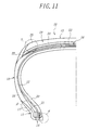
- the tire 10 comprises a pair of bead portions 11, a pair of sidewall portions 12, and a tread portion 13. And also, the tire 10 comprises a radial carcass 15 of one or more rubberized plies extending between the pair of the bead portions 11 embedding a pair of bead cores 14 therein and reinforcing the portions 11, 12, 13 and a belt 16 superimposed about the radial carcass 15 and reinforcing the tread portion 13. An end portion of the radial carcass 15 is terminated between the pair of the bead cores 14.
- the tire 10 has an innerliner rubber 20 as an inside rubber member and a bead filler rubber 21 as an inner reinforcing rubber member from the bead portion 11 to the sidewall portion 12. And also, the tire 10 has sometimes a mini-sidewall rubber 22 mediating between the sidewall rubber 18 and a tread rubber 19 as an outer rubber member.
- the tread rubber 19 has a multilayer structure comprised of a tread under cushion rubber 23 for ensuring the adhesion to the belt 16, a tread base rubber 24 as a middle layer and a tread cap rubber 25.
- a coating rubber for reinforcing cords in the radial carcass 15 is NR-based, IR-base or SBR-based rubber composition.
- Such a rubber composition is poor in the adhesion property to the halogenated butyl rubber composition or the butyl rubber composition after the curing and hence the peeling is frequently caused between the two rubbers. Therefore, either of the first laminated rubber member ⁇ A+(A+B) ⁇ and the second laminated rubber member ⁇ A+(A+B)+B ⁇ as mentioned above is applied to the innerliner rubber 20.
- the rubber material A and the rubber material (A+B) or the rubber material (A+B) and the rubber material B are overlapped with each other over an approximately full region.
- the NR-based, IR-based or SBR-based rubber composition is used as the rubber material A, while the halogenated butyl rubber composition or the butyl rubber composition is used as the rubber material B.
- the properties of the rubber composition located near to the radial carcass 15 approach to those of the coating rubber for the reinforcing cords.
- the coating rubber for the reinforcing cords has 100% modulus and 300% modulus higher by not less than 1 MPa than those of the halogenated butyl rubber composition or the butyl rubber composition.
- the above second laminated rubber member ⁇ A+(A+B)+B ⁇ is applied to the innerliner rubber 20, and thereafter BR-based rubber composition for the chafer rubber 17 is used as the rubber material C to form the third laminated rubber member ⁇ A+(A+B)+B+(B+C) ⁇ or the fourth laminated rubber member ⁇ A+(A+B)+B+(B+C)+C ⁇ .
- the rubber material (B+C) or ⁇ (B+C)+C ⁇ is overlapped with a part of both sides of the second laminated rubber member ⁇ A+(A+B)+B ⁇ .
- 100% modulus of the chafer rubber 17 is 4.0-8.0 MPa and is higher by not less than 1 MPa than 100% modulus of the rubber material B after the curing. Thus, the toe breakage can be avoided.
- a ⁇ -region shown by a circle of dot-dash line in Fig. 11 is created a large bending strain under loading applied to the tire 10.
- the sidewall rubber 18 having excellent weather resistance and bending resistance has 100% modulus of 1.0-2.5 MPa
- the bead filler rubber 21 for reinforcing the bead portion 11 has 100% modulus of 5.0-10.0 MPa.
- the ⁇ -region indicates a modulus distribution shown in Fig. 10 in the direction of the rubber gauge, so that the peeling at the rubber boundary face is frequently caused in the ⁇ -region due to the step difference of modulus shown in Fig. 10.
- the fourth laminated rubber member ⁇ A+(A+B)+B+(B+C)+C ⁇ is applied to the bead filler rubber 21, sidewall rubber 18 and chafer rubber 17, wherein the rubber material A is a rubber composition for the bead filler 21, the rubber material B is a rubber composition for the sidewall rubber 18 and the rubber material C is a rubber composition for the chafer rubber 17.
- the modulus distribution becomes curved line as shown in Fig. 10 and hence the step difference of modulus is actually removed and the peeling at the rubber boundary face hardly occurs. Even in this case, the rubber materials to be laminated are partly overlapped with each other.
- a ⁇ -region shown by a circle of dot-dash line in Fig. 11 is created a large strain under loading applied to the tire 10.
- 300% modulus is 15-18 MPa in the same kind of the tread under cushion rubber 23 as a high modulus coating rubber suitable for steel cords, 5-12 MPa in the tread base rubber 24 being rich in the cushionability, and 7-13 MPa in the tread cap rubber 25 having excellent wear resistance and steering stability.
- the modulus difference between the adjoining rubbers is not less than 1.0 MPa. Therefore, the ⁇ -region indicates a modulus distribution shown in Fig. 10 in the direction of the rubber gauge, so that the peeling at the rubber boundary face is frequently caused in the ⁇ -region due to the step difference of modulus shown in Fig. 10.
- the fourth laminated rubber member is applied to the tread rubber 19, wherein the rubber material A is a rubber composition for the tread under cushion rubber 23, the rubber material B is a rubber composition for the tread base rubber 24 and the rubber material C is a rubber composition for the tread cap rubber 25.
- the modulus distribution becomes curved line as shown in Fig. 10 and hence the step difference of modulus is actually removed and the peeling at the rubber boundary face hardly occurs.
- the rubber materials to be laminated are overlapped with each other over an approximately full width.
- a fifth laminated rubber member may be formed by using a rubber material D as a rubber composition for the mini-sidewall rubber 22 having an excellent conductivity.
- the rubber material D is a rubber composition for the sidewall rubber 18.
- a rubber layer made of the rubber material D is overlapped with a part of both sides of the other laminated rubber members.
- Fig. 12 diagrammatically shows a section of an engine mount block 30 used in an automobile.
- the engine mount block 30 is required to use a rubber having a vibration damping effect as high as possible on one hand and a rubber having an excellent weather resistance on the other hand. Therefore, the second laminated rubber member ⁇ A+(A+B)+B ⁇ is applied to the engine mount block 30.
- the rubber material A as a rubber composition having an excellent weather resistance is used in an outer rubber of the engine mount block 30 and the rubber material B as a rubber composition having a high vibration damping effect is used in an inner rubber thereof.
- the performances required in the engine mount block can sufficiently be attained by using the rubber materials having conflicting rubber properties.
- the rubber material A, rubber blend (A+B) and rubber material B are overlapped with each other over an approximately full region.
- the lamination method according to the invention as previously mentioned is applicable to a rubber vibration isolator, a marine fender and the like,in addition to the engine mount block 30.
- a method of laminating band-shaped uncured rubber materials with a high productivity in the production of tire and other rubber composites which can simultaneously establish the holding of sufficient durability of the tire or other rubber composite and the application of optimum planned rubber composition to each rubber member under the forming automation in space saving and easily realize high-accuracy desirable sectional shape and arrangement of each rubber member.
- the invention can provide an apparatus for laminating band-shaped uncured rubber materials in a low cost which has a simple and compact structure and can surely realize the lamination method as mentioned above.
Landscapes
- Engineering & Computer Science (AREA)
- Mechanical Engineering (AREA)
- Tyre Moulding (AREA)
- Tires In General (AREA)
- Extrusion Moulding Of Plastics Or The Like (AREA)
- Shaping Of Tube Ends By Bending Or Straightening (AREA)
Applications Claiming Priority (4)
| Application Number | Priority Date | Filing Date | Title |
|---|---|---|---|
| JP19298698 | 1998-07-08 | ||
| JP19298698 | 1998-07-08 | ||
| JP17509599 | 1999-06-22 | ||
| JP17509599A JP4315526B2 (ja) | 1998-07-08 | 1999-06-22 | 帯状未加硫ゴムの積層方法 |
Publications (3)
| Publication Number | Publication Date |
|---|---|
| EP0970797A2 true EP0970797A2 (fr) | 2000-01-12 |
| EP0970797A3 EP0970797A3 (fr) | 2000-10-18 |
| EP0970797B1 EP0970797B1 (fr) | 2003-03-05 |
Family
ID=26496470
Family Applications (1)
| Application Number | Title | Priority Date | Filing Date |
|---|---|---|---|
| EP99305454A Expired - Lifetime EP0970797B1 (fr) | 1998-07-08 | 1999-07-08 | Procédé et appareil pour laminer des bandes de caoutchouc non vulcanisé |
Country Status (5)
| Country | Link |
|---|---|
| US (1) | US20060096696A1 (fr) |
| EP (1) | EP0970797B1 (fr) |
| JP (1) | JP4315526B2 (fr) |
| DE (1) | DE69905655T2 (fr) |
| ES (1) | ES2190635T3 (fr) |
Cited By (23)
| Publication number | Priority date | Publication date | Assignee | Title |
|---|---|---|---|---|
| EP1016555A3 (fr) * | 1998-12-28 | 2001-03-21 | The Yokohama Rubber Co., Ltd. | Pneumatique pour voiture et son procédé de fabrication |
| WO2002016118A1 (fr) * | 2000-08-21 | 2002-02-28 | Fuji Seiko Co., Ltd. | Systeme de production de pneumatiques et procede de production correspondant |
| WO2002060676A1 (fr) * | 2001-01-31 | 2002-08-08 | Bridgestone Corporation | Procede de fabrication de pneumatique |
| WO2002078981A1 (fr) * | 2001-03-29 | 2002-10-10 | Pirelli Pneumatici S.P.A. | Procede de formation d'une structure de ceinture dans un pneu, en particulier pour des pneus de motocyclette |
| WO2003041941A1 (fr) * | 2001-11-12 | 2003-05-22 | Bridgestone Corporation | Procede de production d'un element en caoutchouc non vulcanise et d'un bandage |
| WO2004106037A1 (fr) * | 2003-05-21 | 2004-12-09 | Stowe Woodward, Llc | Procede de formation d'element de couverture pour rouleau industriel |
| EP1439078A4 (fr) * | 2001-09-27 | 2005-04-27 | Sumitomo Rubber Ind | Pneumatique et procede de fabrication de celui-ci |
| EP1418043A3 (fr) * | 2002-11-08 | 2005-05-25 | The Goodyear Tire & Rubber Company | Procédé et dispositif pour la fabrication d'un élément annulaire en caoutchouc pour pneumatiques |
| WO2006046259A1 (fr) | 2004-10-27 | 2006-05-04 | Pirelli Tyre S.P.A. | Pneumatique pour vehicule, procede et dispositif de confection |
| WO2006046162A1 (fr) * | 2004-10-27 | 2006-05-04 | Pirelli Tyre S.P.A. | Procede et appareil de fabrication d'articles en couches en materiau elastomere |
| WO2006061860A1 (fr) * | 2004-12-07 | 2006-06-15 | Pirelli Pneumatici S.P.A. | Procede et appareil destines a fabriquer des articles a couches a partir de materiaux elastomeres |
| US7094302B2 (en) | 2001-03-29 | 2006-08-22 | Pirelli Pneumatici S.P.A. | Method of forming a belt structure in a tire, in particular for motorcycle wheels |
| EP1803545A3 (fr) * | 2005-12-28 | 2007-12-26 | Sumitomo Rubber Industries, Ltd. | Procédé de fabrication d'éléments en caoutchouc pour pneumatiques |
| US7780809B2 (en) | 2005-08-04 | 2010-08-24 | The Goodyear Tire & Rubber Company | Method for forming elastomeric tire component and a tire |
| EP2191985A4 (fr) * | 2005-10-17 | 2010-10-06 | Bridgestone Corp | Pneumatique, appareil et procede de moulage d'un pneumatique |
| EP2338661A1 (fr) * | 2009-12-23 | 2011-06-29 | The Goodyear Tire & Rubber Company | Procédé et appareil de formation d'un article en caoutchouc |
| EP2338660A1 (fr) * | 2009-12-23 | 2011-06-29 | The Goodyear Tire & Rubber Company | Méthode et appareil pour l'application de mélange de caoutchouc sur un noyau |
| CN102529589A (zh) * | 2010-12-16 | 2012-07-04 | 住友橡胶工业株式会社 | 充气轮胎 |
| US8323014B2 (en) | 2003-10-31 | 2012-12-04 | Pirelli Pneumatici S.P.A. | Expandable bladder for tyre-curing apparatuses, a manufacturing method thereof, and a process for manufacturing tyres for vehicle wheels |
| US20130075017A1 (en) * | 2011-09-27 | 2013-03-28 | Christian Jean-Marie Kaes | Method for forming stratified rubber article |
| EP2468476B1 (fr) * | 2010-12-22 | 2016-08-03 | The Goodyear Tire & Rubber Company | Procédé de formation de composés de pneu |
| US10287731B2 (en) | 2005-11-08 | 2019-05-14 | Stowe Woodward Licensco Llc | Abrasion-resistant rubber roll cover with polyurethane coating |
| EP3670167A1 (fr) * | 2018-12-19 | 2020-06-24 | The Goodyear Tire & Rubber Company | Procédé de formation d'un composant de pneumatique et composant de pneumatique |
Families Citing this family (36)
| Publication number | Priority date | Publication date | Assignee | Title |
|---|---|---|---|---|
| DE69919233T3 (de) * | 1999-11-19 | 2010-12-30 | Pirelli Tyre S.P.A. | Verfahren zur herstellung von reifenbestandteilen aus elastomerischem material |
| JP2001206012A (ja) * | 2000-01-28 | 2001-07-31 | Bridgestone Corp | 重荷重用空気入りタイヤ |
| JP4765149B2 (ja) * | 2000-07-10 | 2011-09-07 | 横浜ゴム株式会社 | 重荷重用空気入りタイヤ |
| JP4765148B2 (ja) * | 2000-07-10 | 2011-09-07 | 横浜ゴム株式会社 | 不整地走行に適した重荷重用空気入りタイヤ |
| JP2002200677A (ja) * | 2000-12-28 | 2002-07-16 | Bridgestone Corp | 空気入りタイヤの製造方法 |
| JP2002347135A (ja) * | 2001-05-29 | 2002-12-04 | Bridgestone Corp | タイヤの製造方法 |
| DE60210444T2 (de) * | 2001-05-29 | 2007-04-12 | Pirelli Pneumatici S.P.A. | Automatischer prozess und automatische anlage zur reifenherstellung |
| JP2002355878A (ja) * | 2001-05-30 | 2002-12-10 | Bridgestone Corp | グリーンタイヤの製造方法およびその装置 |
| JP4300188B2 (ja) * | 2002-11-05 | 2009-07-22 | ピレリ・タイヤ・ソチエタ・ペル・アツィオーニ | 車輪用タイヤを製造する方法およびプラント |
| US8104523B2 (en) * | 2003-12-30 | 2012-01-31 | Pirelli Pneumatici S.P.A. | Pneumatic tire and process for its manufacture |
| JP4523815B2 (ja) * | 2004-08-26 | 2010-08-11 | 住友ゴム工業株式会社 | 重荷重用空気入りタイヤ及びその製造方法 |
| JP2006224871A (ja) * | 2005-02-18 | 2006-08-31 | Bridgestone Corp | 空気入りタイヤ |
| JP5054303B2 (ja) * | 2005-12-20 | 2012-10-24 | 住友ゴム工業株式会社 | 空気入りタイヤ及びその製造方法 |
| JP4847127B2 (ja) * | 2005-12-28 | 2011-12-28 | 住友ゴム工業株式会社 | 空気入りタイヤ |
| JP4944451B2 (ja) * | 2006-02-02 | 2012-05-30 | 株式会社ブリヂストン | 重荷重用空気入りタイヤ |
| JP4866097B2 (ja) * | 2006-02-15 | 2012-02-01 | 住友ゴム工業株式会社 | タイヤのゴム構成部製造方法、及びそれに用いるゴム押出し装置 |
| DE102006019262A1 (de) * | 2006-04-26 | 2007-10-31 | Continental Aktiengesellschaft | Verfahren zur Herstellung eines Laufstreifens für einen Fahrzeugreifen, insbesondere eines Fahrzeugluftreifens |
| JP5394062B2 (ja) | 2006-07-10 | 2014-01-22 | 東洋ゴム工業株式会社 | タイヤ用インナ−ライナゴム部材を成型する方法 |
| DE102008016625A1 (de) * | 2007-04-13 | 2008-12-04 | Toyo Tire & Rubber Co., Ltd. | Verfahren zum Entwerfen von Reifen |
| JP5065762B2 (ja) * | 2007-05-18 | 2012-11-07 | 住友ゴム工業株式会社 | 空気入りタイヤ |
| JP5114105B2 (ja) * | 2007-06-21 | 2013-01-09 | 東洋ゴム工業株式会社 | タイヤ用ゴム部材の製造方法 |
| JP2011127628A (ja) * | 2009-12-15 | 2011-06-30 | Toyo Tire & Rubber Co Ltd | 鉄道車両用軸ばねの製造方法 |
| CN102811869B (zh) * | 2010-02-04 | 2015-04-15 | 株式会社普利司通 | 翻新轮胎 |
| IT1399702B1 (it) * | 2010-04-26 | 2013-04-26 | Marangoni Meccanica | Metodo e gruppo per la rullatura di uno pneumatico |
| JP5247852B2 (ja) | 2010-11-05 | 2013-07-24 | 住友ゴム工業株式会社 | 空気入りタイヤの製造方法 |
| JP5225431B2 (ja) * | 2010-12-06 | 2013-07-03 | 住友ゴム工業株式会社 | ストリップ、その製造方法および空気入りタイヤの製造方法 |
| JP5225364B2 (ja) * | 2010-12-08 | 2013-07-03 | 住友ゴム工業株式会社 | ストリップ、その製造方法および空気入りタイヤの製造方法 |
| KR101215521B1 (ko) | 2011-10-24 | 2012-12-26 | 한국타이어월드와이드 주식회사 | 중하중용 타이어의 비드필러 제조장치와 그 제조방법 |
| JP6091006B2 (ja) * | 2013-09-30 | 2017-03-08 | 東洋ゴム工業株式会社 | 空気入りタイヤの製造方法及び空気入りタイヤ |
| CN103950769A (zh) * | 2014-05-04 | 2014-07-30 | 陈婷 | 一种胶条挤出机的万向引导装置 |
| JP2016043559A (ja) * | 2014-08-22 | 2016-04-04 | 住友ゴム工業株式会社 | ダイプレートおよび押出成形装置 |
| AT516295A1 (de) | 2014-09-10 | 2016-04-15 | Next Generation Analytics Gmbh | Vorrichtung und Verfahren für die Herstellung und zum Testen von Werkstücken |
| WO2016109012A1 (fr) | 2014-12-31 | 2016-07-07 | Bridgestone Americas Tire Operations, Llc | Procédés et appareils de fabrication additive à partir de caoutchouc |
| US12109773B2 (en) | 2018-12-19 | 2024-10-08 | The Goodyear Tire & Rubber Company | Method and apparatus for forming an apex |
| US20200198271A1 (en) * | 2018-12-19 | 2020-06-25 | The Goodyear Tire & Rubber Company | Method of making composite innerliner |
| JP7375480B2 (ja) * | 2019-11-07 | 2023-11-08 | 住友ゴム工業株式会社 | タイヤの製造方法 |
Family Cites Families (14)
| Publication number | Priority date | Publication date | Assignee | Title |
|---|---|---|---|---|
| US2849049A (en) * | 1956-05-16 | 1958-08-26 | Firestone Tire & Rubber Co | Method of forming an endless tire tread and sidewall portion on a carcass band and product thereof |
| US3223572A (en) * | 1959-12-24 | 1965-12-14 | American Mach & Foundry | Machine for building a tread on pneumatic tires |
| BE638450A (fr) * | 1962-10-12 | |||
| CH479391A (de) * | 1967-10-17 | 1969-10-15 | Leuna Werke Veb | Verfahren und Vorrichtung zum Ummanteln von Rotationskörpern |
| JPS54132904A (en) * | 1978-04-06 | 1979-10-16 | Bridgestone Corp | Pneumatic tire with improved heating property |
| FR2603841B1 (fr) * | 1986-09-17 | 1989-02-24 | Michelin & Cie | Procede de fabrication d'un pneumatique avec pose des produits caoutchouteux et des elements de renforcement sur un support, dispositif de pose des produits caoutchouteux et machine qui utilise de tel(s) dispositif(s) |
| GB8724849D0 (en) * | 1987-10-23 | 1987-11-25 | Apsley Metals Ltd | Manufacture of tyres |
| US5021493A (en) * | 1990-03-21 | 1991-06-04 | The Goodyear Tire & Rubber Company | Rubber composition and tire with component(s) thereof |
| US5148943A (en) * | 1991-06-17 | 1992-09-22 | Hydreclaim Corporation | Method and apparatus for metering and blending different material ingredients |
| JPH07156283A (ja) * | 1993-12-09 | 1995-06-20 | Mitsubishi Rayon Co Ltd | プラスチックシート状物の製造方法 |
| CA2140999A1 (fr) * | 1994-11-07 | 1996-05-08 | Jennifer Leigh Gabor | Bande de roulement triplex |
| US6179029B1 (en) * | 1997-04-02 | 2001-01-30 | Compagnie G{acute over (e)}n{acute over (e)}rale des Etablissements Michelin - Michelin & Cie | Tire having an improved carcass |
| US6039826A (en) * | 1997-04-22 | 2000-03-21 | The Yokohama Rubber Co., Ltd. | Method of forming green tire with strip winding |
| US6277314B1 (en) * | 1998-02-04 | 2001-08-21 | Flextech Packaging, Ltd. | System and method for producing polymeric film |
-
1999
- 1999-06-22 JP JP17509599A patent/JP4315526B2/ja not_active Expired - Fee Related
- 1999-07-08 DE DE69905655T patent/DE69905655T2/de not_active Expired - Fee Related
- 1999-07-08 EP EP99305454A patent/EP0970797B1/fr not_active Expired - Lifetime
- 1999-07-08 ES ES99305454T patent/ES2190635T3/es not_active Expired - Lifetime
-
2005
- 2005-12-27 US US11/316,863 patent/US20060096696A1/en not_active Abandoned
Cited By (35)
| Publication number | Priority date | Publication date | Assignee | Title |
|---|---|---|---|---|
| EP1016555A3 (fr) * | 1998-12-28 | 2001-03-21 | The Yokohama Rubber Co., Ltd. | Pneumatique pour voiture et son procédé de fabrication |
| WO2002016118A1 (fr) * | 2000-08-21 | 2002-02-28 | Fuji Seiko Co., Ltd. | Systeme de production de pneumatiques et procede de production correspondant |
| US6921446B2 (en) | 2000-08-21 | 2005-07-26 | Fuji Seiko Co., Ltd. | System and method for producing tire |
| WO2002060676A1 (fr) * | 2001-01-31 | 2002-08-08 | Bridgestone Corporation | Procede de fabrication de pneumatique |
| WO2002078981A1 (fr) * | 2001-03-29 | 2002-10-10 | Pirelli Pneumatici S.P.A. | Procede de formation d'une structure de ceinture dans un pneu, en particulier pour des pneus de motocyclette |
| US7094302B2 (en) | 2001-03-29 | 2006-08-22 | Pirelli Pneumatici S.P.A. | Method of forming a belt structure in a tire, in particular for motorcycle wheels |
| US7131476B2 (en) | 2001-09-27 | 2006-11-07 | Sumitomo Rubber Industries, Ltd. | Pneumatic tire and method of manufacturing the tire |
| EP1439078A4 (fr) * | 2001-09-27 | 2005-04-27 | Sumitomo Rubber Ind | Pneumatique et procede de fabrication de celui-ci |
| WO2003041941A1 (fr) * | 2001-11-12 | 2003-05-22 | Bridgestone Corporation | Procede de production d'un element en caoutchouc non vulcanise et d'un bandage |
| CN100420565C (zh) * | 2001-11-12 | 2008-09-24 | 株式会社普利司通 | 用于制造未硫化橡胶构件的工艺和轮胎 |
| EP1454732A4 (fr) * | 2001-11-12 | 2005-07-06 | Bridgestone Corp | Procede de production d'un element en caoutchouc non vulcanise et d'un bandage |
| EP1418043A3 (fr) * | 2002-11-08 | 2005-05-25 | The Goodyear Tire & Rubber Company | Procédé et dispositif pour la fabrication d'un élément annulaire en caoutchouc pour pneumatiques |
| US6874232B2 (en) | 2003-05-21 | 2005-04-05 | Stowe Woodward, Llc | Method for forming cover for industrial roll |
| WO2004106037A1 (fr) * | 2003-05-21 | 2004-12-09 | Stowe Woodward, Llc | Procede de formation d'element de couverture pour rouleau industriel |
| US8323014B2 (en) | 2003-10-31 | 2012-12-04 | Pirelli Pneumatici S.P.A. | Expandable bladder for tyre-curing apparatuses, a manufacturing method thereof, and a process for manufacturing tyres for vehicle wheels |
| US8961857B2 (en) | 2003-10-31 | 2015-02-24 | Pirelli Tyre S.P.A. | Expandable bladder for tyre-curing apparatuses, a manufacturing method thereof, and a process for manufacturing tyres for vehicle wheels |
| KR101146236B1 (ko) * | 2004-10-27 | 2012-05-15 | 피렐리 타이어 소시에떼 퍼 아찌오니 | 차량용 공기 타이어, 차량용 공기 타이어 제조 방법 및 제조 기기 |
| WO2006046162A1 (fr) * | 2004-10-27 | 2006-05-04 | Pirelli Tyre S.P.A. | Procede et appareil de fabrication d'articles en couches en materiau elastomere |
| CN101052537B (zh) * | 2004-10-27 | 2011-05-11 | 倍耐力轮胎股份公司 | 用于车辆的充气轮胎及其制造方法和装置 |
| WO2006046259A1 (fr) | 2004-10-27 | 2006-05-04 | Pirelli Tyre S.P.A. | Pneumatique pour vehicule, procede et dispositif de confection |
| WO2006061860A1 (fr) * | 2004-12-07 | 2006-06-15 | Pirelli Pneumatici S.P.A. | Procede et appareil destines a fabriquer des articles a couches a partir de materiaux elastomeres |
| US7780809B2 (en) | 2005-08-04 | 2010-08-24 | The Goodyear Tire & Rubber Company | Method for forming elastomeric tire component and a tire |
| EP2191985A4 (fr) * | 2005-10-17 | 2010-10-06 | Bridgestone Corp | Pneumatique, appareil et procede de moulage d'un pneumatique |
| US10287731B2 (en) | 2005-11-08 | 2019-05-14 | Stowe Woodward Licensco Llc | Abrasion-resistant rubber roll cover with polyurethane coating |
| EP1803545A3 (fr) * | 2005-12-28 | 2007-12-26 | Sumitomo Rubber Industries, Ltd. | Procédé de fabrication d'éléments en caoutchouc pour pneumatiques |
| EP2338661A1 (fr) * | 2009-12-23 | 2011-06-29 | The Goodyear Tire & Rubber Company | Procédé et appareil de formation d'un article en caoutchouc |
| EP2338660A1 (fr) * | 2009-12-23 | 2011-06-29 | The Goodyear Tire & Rubber Company | Méthode et appareil pour l'application de mélange de caoutchouc sur un noyau |
| CN102107539B (zh) * | 2009-12-23 | 2015-05-20 | 固特异轮胎和橡胶公司 | 形成分层橡胶制品的方法 |
| CN102107539A (zh) * | 2009-12-23 | 2011-06-29 | 固特异轮胎和橡胶公司 | 形成分层橡胶制品的方法 |
| CN102529589A (zh) * | 2010-12-16 | 2012-07-04 | 住友橡胶工业株式会社 | 充气轮胎 |
| CN102529589B (zh) * | 2010-12-16 | 2016-01-20 | 住友橡胶工业株式会社 | 充气轮胎 |
| EP2468476B1 (fr) * | 2010-12-22 | 2016-08-03 | The Goodyear Tire & Rubber Company | Procédé de formation de composés de pneu |
| US20130075017A1 (en) * | 2011-09-27 | 2013-03-28 | Christian Jean-Marie Kaes | Method for forming stratified rubber article |
| EP2574443A1 (fr) * | 2011-09-27 | 2013-04-03 | The Goodyear Tire & Rubber Company | Procédé de formation d'un composant de pneu et pneu |
| EP3670167A1 (fr) * | 2018-12-19 | 2020-06-24 | The Goodyear Tire & Rubber Company | Procédé de formation d'un composant de pneumatique et composant de pneumatique |
Also Published As
| Publication number | Publication date |
|---|---|
| US20060096696A1 (en) | 2006-05-11 |
| JP2000079643A (ja) | 2000-03-21 |
| DE69905655D1 (de) | 2003-04-10 |
| JP4315526B2 (ja) | 2009-08-19 |
| EP0970797A3 (fr) | 2000-10-18 |
| DE69905655T2 (de) | 2003-11-27 |
| ES2190635T3 (es) | 2003-08-01 |
| EP0970797B1 (fr) | 2003-03-05 |
Similar Documents
| Publication | Publication Date | Title |
|---|---|---|
| EP0970797B1 (fr) | Procédé et appareil pour laminer des bandes de caoutchouc non vulcanisé | |
| RU2225792C2 (ru) | Способ изготовления пневматической шины | |
| EP1201414B1 (fr) | Procédé de fabrication d'un flanc de pneumatique | |
| US6941993B2 (en) | Tire with specified reinforcing ply | |
| US8820375B2 (en) | Method and apparatus for improved tread splicing | |
| CN1159171C (zh) | 导电轮胎和挤压导电成型部件的方法 | |
| EP1629964B1 (fr) | Procédé de fabrication d'un pneu et pneu ainsi obtenu | |
| EP1142695B1 (fr) | Procédé pour la confection de pneus | |
| WO2008007420A1 (fr) | Matériau en bande de caoutchouc | |
| EP1803545A2 (fr) | Procédé de fabrication d'éléments en caoutchouc pour pneumatiques | |
| EP1454732A1 (fr) | Procede de production d'un element en caoutchouc non vulcanise et d'un bandage | |
| EP2121294B1 (fr) | Processus de fabrication de pneus par application de bandes de largeurs différentes | |
| JP2008307749A (ja) | 更生タイヤの製造方法及び製造装置 | |
| EP1800845B1 (fr) | Pneumatique et son procédé de fabrication. | |
| US20050034802A1 (en) | Production method for unvulcanized rubber member and tire | |
| US20090008012A1 (en) | Pneumatic tire, arrangement structure and manufacturing method of the same | |
| JP2009292000A (ja) | 空気入りタイヤの製造方法および装置 | |
| JP2003191711A (ja) | タイヤ及びその製造方法 | |
| CN103249547A (zh) | 构建轮胎的方法和设备,以及由此得到的生胎和硫化轮胎 | |
| CN1292748A (zh) | 轮胎部件成型方法和设备 |
Legal Events
| Date | Code | Title | Description |
|---|---|---|---|
| PUAI | Public reference made under article 153(3) epc to a published international application that has entered the european phase |
Free format text: ORIGINAL CODE: 0009012 |
|
| AK | Designated contracting states |
Kind code of ref document: A2 Designated state(s): DE ES FR GB IT |
|
| AX | Request for extension of the european patent |
Free format text: AL;LT;LV;MK;RO;SI |
|
| PUAL | Search report despatched |
Free format text: ORIGINAL CODE: 0009013 |
|
| AK | Designated contracting states |
Kind code of ref document: A3 Designated state(s): AT BE CH CY DE DK ES FI FR GB GR IE IT LI LU MC NL PT SE |
|
| AX | Request for extension of the european patent |
Free format text: AL;LT;LV;MK;RO;SI |
|
| RIC1 | Information provided on ipc code assigned before grant |
Free format text: 7B 29C 47/06 A, 7B 29D 30/60 B, 7B 29C 47/10 B, 7B 29C 31/10 B |
|
| 17P | Request for examination filed |
Effective date: 20001108 |
|
| AKX | Designation fees paid |
Free format text: DE ES FR GB IT |
|
| GRAG | Despatch of communication of intention to grant |
Free format text: ORIGINAL CODE: EPIDOS AGRA |
|
| 17Q | First examination report despatched |
Effective date: 20011030 |
|
| GRAG | Despatch of communication of intention to grant |
Free format text: ORIGINAL CODE: EPIDOS AGRA |
|
| GRAH | Despatch of communication of intention to grant a patent |
Free format text: ORIGINAL CODE: EPIDOS IGRA |
|
| GRAH | Despatch of communication of intention to grant a patent |
Free format text: ORIGINAL CODE: EPIDOS IGRA |
|
| GRAA | (expected) grant |
Free format text: ORIGINAL CODE: 0009210 |
|
| AK | Designated contracting states |
Designated state(s): DE ES FR GB IT |
|
| REG | Reference to a national code |
Ref country code: GB Ref legal event code: FG4D |
|
| REF | Corresponds to: |
Ref document number: 69905655 Country of ref document: DE Date of ref document: 20030410 Kind code of ref document: P |
|
| REG | Reference to a national code |
Ref country code: ES Ref legal event code: FG2A Ref document number: 2190635 Country of ref document: ES Kind code of ref document: T3 |
|
| ET | Fr: translation filed | ||
| PLBE | No opposition filed within time limit |
Free format text: ORIGINAL CODE: 0009261 |
|
| STAA | Information on the status of an ep patent application or granted ep patent |
Free format text: STATUS: NO OPPOSITION FILED WITHIN TIME LIMIT |
|
| 26N | No opposition filed |
Effective date: 20031208 |
|
| PGFP | Annual fee paid to national office [announced via postgrant information from national office to epo] |
Ref country code: DE Payment date: 20070705 Year of fee payment: 9 |
|
| PG25 | Lapsed in a contracting state [announced via postgrant information from national office to epo] |
Ref country code: DE Free format text: LAPSE BECAUSE OF NON-PAYMENT OF DUE FEES Effective date: 20090203 |
|
| PGFP | Annual fee paid to national office [announced via postgrant information from national office to epo] |
Ref country code: ES Payment date: 20090804 Year of fee payment: 11 |
|
| REG | Reference to a national code |
Ref country code: ES Ref legal event code: FD2A Effective date: 20110818 |
|
| PG25 | Lapsed in a contracting state [announced via postgrant information from national office to epo] |
Ref country code: ES Free format text: LAPSE BECAUSE OF NON-PAYMENT OF DUE FEES Effective date: 20100709 |
|
| REG | Reference to a national code |
Ref country code: FR Ref legal event code: CA Effective date: 20140812 |
|
| PGFP | Annual fee paid to national office [announced via postgrant information from national office to epo] |
Ref country code: GB Payment date: 20140721 Year of fee payment: 16 |
|
| PGFP | Annual fee paid to national office [announced via postgrant information from national office to epo] |
Ref country code: IT Payment date: 20140730 Year of fee payment: 16 |
|
| GBPC | Gb: european patent ceased through non-payment of renewal fee |
Effective date: 20150708 |
|
| PG25 | Lapsed in a contracting state [announced via postgrant information from national office to epo] |
Ref country code: IT Free format text: LAPSE BECAUSE OF NON-PAYMENT OF DUE FEES Effective date: 20150708 Ref country code: GB Free format text: LAPSE BECAUSE OF NON-PAYMENT OF DUE FEES Effective date: 20150708 |
|
| REG | Reference to a national code |
Ref country code: FR Ref legal event code: PLFP Year of fee payment: 18 |
|
| PGFP | Annual fee paid to national office [announced via postgrant information from national office to epo] |
Ref country code: FR Payment date: 20160721 Year of fee payment: 18 |
|
| REG | Reference to a national code |
Ref country code: FR Ref legal event code: ST Effective date: 20180330 |
|
| PG25 | Lapsed in a contracting state [announced via postgrant information from national office to epo] |
Ref country code: FR Free format text: LAPSE BECAUSE OF NON-PAYMENT OF DUE FEES Effective date: 20170731 |