EP1803545A2 - Procédé de fabrication d'éléments en caoutchouc pour pneumatiques - Google Patents
Procédé de fabrication d'éléments en caoutchouc pour pneumatiques Download PDFInfo
- Publication number
- EP1803545A2 EP1803545A2 EP06026803A EP06026803A EP1803545A2 EP 1803545 A2 EP1803545 A2 EP 1803545A2 EP 06026803 A EP06026803 A EP 06026803A EP 06026803 A EP06026803 A EP 06026803A EP 1803545 A2 EP1803545 A2 EP 1803545A2
- Authority
- EP
- European Patent Office
- Prior art keywords
- rubber
- rubber strip
- strip
- winding
- tire
- Prior art date
- Legal status (The legal status is an assumption and is not a legal conclusion. Google has not performed a legal analysis and makes no representation as to the accuracy of the status listed.)
- Granted
Links
- 229920001971 elastomer Polymers 0.000 title claims abstract description 219
- 239000005060 rubber Substances 0.000 title claims abstract description 219
- 238000004519 manufacturing process Methods 0.000 title claims abstract description 17
- 238000004804 winding Methods 0.000 claims abstract description 55
- 239000000463 material Substances 0.000 claims description 10
- 230000002093 peripheral effect Effects 0.000 claims description 7
- 239000002131 composite material Substances 0.000 claims description 3
- 239000011324 bead Substances 0.000 description 5
- 238000000034 method Methods 0.000 description 5
- 239000000203 mixture Substances 0.000 description 5
- 239000011295 pitch Substances 0.000 description 5
- 230000000052 comparative effect Effects 0.000 description 3
- 238000010276 construction Methods 0.000 description 3
- 238000001125 extrusion Methods 0.000 description 3
- 230000000694 effects Effects 0.000 description 2
- OKTJSMMVPCPJKN-UHFFFAOYSA-N Carbon Chemical compound [C] OKTJSMMVPCPJKN-UHFFFAOYSA-N 0.000 description 1
- 244000043261 Hevea brasiliensis Species 0.000 description 1
- 229910052799 carbon Inorganic materials 0.000 description 1
- 229920003244 diene elastomer Polymers 0.000 description 1
- 238000006073 displacement reaction Methods 0.000 description 1
- 229920003049 isoprene rubber Polymers 0.000 description 1
- 229920003052 natural elastomer Polymers 0.000 description 1
- 229920001194 natural rubber Polymers 0.000 description 1
- 230000002265 prevention Effects 0.000 description 1
- 229920003048 styrene butadiene rubber Polymers 0.000 description 1
Images



Classifications
-
- B—PERFORMING OPERATIONS; TRANSPORTING
- B29—WORKING OF PLASTICS; WORKING OF SUBSTANCES IN A PLASTIC STATE IN GENERAL
- B29D—PRODUCING PARTICULAR ARTICLES FROM PLASTICS OR FROM SUBSTANCES IN A PLASTIC STATE
- B29D30/00—Producing pneumatic or solid tyres or parts thereof
- B29D30/06—Pneumatic tyres or parts thereof (e.g. produced by casting, moulding, compression moulding, injection moulding, centrifugal casting)
- B29D30/08—Building tyres
- B29D30/20—Building tyres by the flat-tyre method, i.e. building on cylindrical drums
- B29D30/30—Applying the layers; Guiding or stretching the layers during application
- B29D30/3028—Applying the layers; Guiding or stretching the layers during application by feeding a continuous band and winding it helically, i.e. the band is fed while being advanced along the drum axis, to form an annular element
-
- B—PERFORMING OPERATIONS; TRANSPORTING
- B29—WORKING OF PLASTICS; WORKING OF SUBSTANCES IN A PLASTIC STATE IN GENERAL
- B29D—PRODUCING PARTICULAR ARTICLES FROM PLASTICS OR FROM SUBSTANCES IN A PLASTIC STATE
- B29D30/00—Producing pneumatic or solid tyres or parts thereof
- B29D30/06—Pneumatic tyres or parts thereof (e.g. produced by casting, moulding, compression moulding, injection moulding, centrifugal casting)
- B29D30/52—Unvulcanised treads, e.g. on used tyres; Retreading
- B29D30/58—Applying bands of rubber treads, i.e. applying camel backs
- B29D30/60—Applying bands of rubber treads, i.e. applying camel backs by winding narrow strips
-
- B—PERFORMING OPERATIONS; TRANSPORTING
- B29—WORKING OF PLASTICS; WORKING OF SUBSTANCES IN A PLASTIC STATE IN GENERAL
- B29D—PRODUCING PARTICULAR ARTICLES FROM PLASTICS OR FROM SUBSTANCES IN A PLASTIC STATE
- B29D30/00—Producing pneumatic or solid tyres or parts thereof
- B29D30/06—Pneumatic tyres or parts thereof (e.g. produced by casting, moulding, compression moulding, injection moulding, centrifugal casting)
- B29D30/72—Side-walls
Definitions
- the present invention relates to a strip wind construction method of forming a rubber member for a tire by spirally winding a rubber strip, and more particularly to a manufacturing method of a rubber member for a tire, which can reduce an air remnant in the rubber member.
- An object of the present invention is to provide a manufacturing method of a rubber member for a tire, which can reduce an air reservoir even in the case of using a rubber strip having a rectangular cross section in an STW method.
- a manufacturing method of a rubber member for a tire by spirally winding a ribbon-shaped unvulcanized rubber strip around an approximately cylindrical wound body, wherein the rubber member is formed by spirally winding the rubber strip and employs a plurality of rubber layers overlapping in inner and outer sides in a radial direction, and a torsional direction of a spiral and an axial winding direction are set identical between a first rubber strip forming a first rubber layer in an inner side in a radial direction, and a second rubber strip forming a second rubber layer by spirally winding in an outer side thereof.
- the present invention can be structured such that spiral directions of the steps generated by the spiral winding are aligned between the inner and outer sides, by setting the torsional direction of the spiral and the axial winding direction identical, and the steps are coincided with each other between the first and second rubber layers. At this time, it is possible to reduce a dead space so as to make them close to each other, and it is possible to suppress the air reservoir.
- the structure can be made such that the first rubber strip and the second rubber strip are formed as a wide composite rubber strip in which side edges of the strips are bonded to each other side by side, prior to the winding.
- Fig. 1 exemplifies a case that a pneumatic tire is constituted by a radial tire for a passenger car.
- a tire 1 includes plural kinds of tire rubber members G having different rubber compositions.
- Figs. 2 and 3 show a case that the rubber member G is constituted as the sidewall rubber G2.
- the sidewall rubber G2 comprises a first rubber layer 11 and a second rubber layer 12, and is wound around an outer peripheral surface 14A of a former 14.
- the first rubber layer 11 is formed by spirally winding a first rubber strip T1 in an inner side in a radial direction
- the second rubber layer 12 is formed by spirally winding a second rubber strip T2 (rubber strip T1, T2 may be generically called as a rubber strip T) in an outer side thereof.
- a torsional direction r of the spiral and an axial winding direction d are set to be identical.
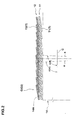
- the torsional direction r of the spiral means, as shown in Fig. 4 - 7 (in which an upper half is shown by a cross sectional view, and a lower half is shown by a plan view), a torsional direction which a step line a generated by the spiral winding of the rubber strip T forms around a center line C thereof, in the plan view in which the center line C is arranged horizontally.
- the axial winding direction d is called as a right axial winding direction dr in the case that the rubber strip T is spirally wound in a right direction in the drawing with respect to an axial direction of a former 14 around which the rubber strip T is wound, and is called as a left axial winding direction dl in the case that it is in a left direction.
- Both of Figs. 4 and 5 correspond to the left axial winding direction dl.
- Fig. 4 shows a case of the rightward torsion rr and the left axial winding direction dl
- Fig. 5 shows a case of the leftward torsion rl and the left axial winding direction dl
- Fig. 6 shows a case of the rightward torsion rr and the right axial winding direction dr
- Fig. 7 shows a case of the leftward torsion rl, and the right axial winding direction dr.
- Figs. 4 to 7 shows a diameter of an outer peripheral surface 14A of the former 14 as being abnormally small.
- the torsional directions r and the axial winding directions d of the first and second rubber strips T1 and T2 of the first and second rubber layers 11 and 12 are made identical. Accordingly, it is possible to align the step lines of the both, and it is possible to extrude and discharge the air. Further, it is preferable to set axial winding pitches p1 and p2 of the first and second rubber strips T to be identical. Further, it is preferable to make thicknesses of the first rubber strip T1 and the second rubber strip T2 identical, in the case of being brought into contact by the step line a.
- the pitch p2 is made equal to pitch p1
- an upper side edge T1a of the first rubber strip T1 of the wound first rubber layer 11 is aligned with a lower side edge T2b of the second rubber strip T2 in side surfaces.
- the upper side edge T1a means a side edge forming an upper side due to a slope at a time of winding the rubber strip T1
- the side edge has a side surface.
- the lower side edge T2b means a side edge forming a lower side due to the slope.
- the rubber member G having the comparatively uniform thickness such as the present embodiment, it is possible to uniformly press the rubber member G to the former by using a comparatively long roller for a pressure forcing. Accordingly, it is possible to make the extrusion of the air easy and it is possible to suppress the generation of the air reservoir.
- the direction of the axial winding direction d is set to the left axial winding direction dl in the first rubber layer 11a, and is set to the right axial winding direction dr in the second rubber layer 12a.
- the torsional direction r is set to the leftward torsion rl in the first rubber layer 11a, and is set to the rightward torsion rr in the second rubber layer 12a. In the case, it reduces the opportunity in which the outward surface in the radial direction of the first rubber strip T1 and the inward surface of the second rubber strip T2 are brought into contact with each other in the state of overlapping in the radial direction, between the first and second rubber layers 11a and 12a. Therefore, it is supposed that the function of preventing the air reservoir between the side surfaces, and suppressing the air reservoir is inferior.
- a normal sidewall rubber material is used as the inside first rubber layer 11, and a rubber having an excellent crack resistance is used as the outside second rubber layer 12 in an outside air side.
- the first rubber strip T1 there is employed a rubber composition in which JISA hardness is not less than 65 and not more than 75, a complex elastic modulus (E*) is not less than 74 kgf/cm 2 and not more than 90 kgf/cm 2 , and a tangent of the loss angle (tan ⁇ ) is not less than 0.25 and not more than 0.35.
- the second rubber strip T2 there is employed a rubber composition in which the JISA hardness is not less than 55 and not more than 65, the complex elastic modulus (E*) is not less than 55 kgf/cm 2 and not more than 60 kgf/cm 2 , and the tangent of the loss angle (tan ⁇ ) is not less than 0.20 and not more than 0.25.
- the rubber member G made of the rubber corresponding to the nature by employing the different material rubbers for the first and second rubber strips T1 and T2.
- the complex elastic modulus (E*) and the tangent of the loss angle (tan ⁇ ) are the values obtained by measuring under 70 ⁇ c, a frequency of 10 Hz, and a dynamic distortion factor of 1% by using a viscous-elasticity spectrometer manufactured by Iwamoto Manufacturing company.
- a thickness a is set between 0.3 and 1.5 mm, and preferably a width w is set between 15 and 35 mm.
- the width w is less than 15 mm or in the case that the thickness t is less than 0.5 mm, a lot of winding frequencies are necessary at a time of finishing a predetermined tread cross sectional shape, and a productivity is lowered.
- the width w becomes more than 35 mm or the thickness t becomes more than 1.5 mm, there is a tendency that it is hard to form a delicate cross sectional shape of the rubber member G.
- Fig. 8 shows the other embodiment in which the first rubber strip T1 and the second rubber strip T2 are formed as a wide composite integral rubber strip T0 in which the strip side edges are bonded to each other.
- the former 14 of the sidewall rubber G2 shown in Figs. 2 and 3 is formed in such a manner that the outer peripheral surface 14A stands in one side in an axial direction so as to be expandable in a disc shape. At this time, it is possible to employ a bladder or the like.
- the rubber strip T or the like which is wound around the cylindrical former 14 is expanded in the disk shape, at a time of expanding of the former 14, and forms the rubber member G corresponding to the sidewall rubber G2.
- the raw cover is attached to a side surface of the carcass 6 of the raw cover by using a manufacturing apparatus.
- the raw cover is expanded in a toroid shape, the belt layer 7, the tread rubber G1 and the like are arranged therein, and the raw cover is formed by attaching the disc-shaped rubber member G to the side surface of the carcass 6.
- the pneumatic tire can be manufactured by vulcanizing the raw cover.
- the sidewall rubber G2 is previously integrally formed with the clinch rubber 16 or the like on the other forming drum.
- the disc-shaped rubber strip T is attached to the side surface of the carcass 6 expanded and deformed in the toroid shape. It is possible to form by directly being wound spirally to the side surface of the carcass 6 around the tire shaft.
- a structure wound in a multiplex manner or partly can be included in the present invention.
- the rubber member G shown in Figs. 2, 3 and 4 to 7, which is in an approximately cylindrical shape, can be adapted as the tread rubber G1.
- the rubber member G can be structured such that the material is different between the first rubber strip T1 and the second rubber strip T2, the first rubber layer 11 can form the base rubber layer of the tread rubber G1, and the second rubber layer 12 can form the cap rubber layer of the tread rubber G2.
- the rubber member in accordance with the present invention can be used for forming the inner liner rubber G3 arranged in the inner side of the carcass 6 and surrounding the tire inner cavity H, the clinch rubber G4, the breaker cushion rubber G5, the bead apex rubber or the like, as mentioned above.
- the present invention is particularly preferable for the pneumatic tire for the passenger car, however, it goes without saying that the present invention can be applied to various tires such as tires for a motor cycle, a truck, a bus and the like, in addition to the tire for the passenger car.
Landscapes
- Engineering & Computer Science (AREA)
- Mechanical Engineering (AREA)
- Tyre Moulding (AREA)
- Tires In General (AREA)
Applications Claiming Priority (1)
| Application Number | Priority Date | Filing Date | Title |
|---|---|---|---|
| JP2005379516A JP4891613B2 (ja) | 2005-12-28 | 2005-12-28 | タイヤ用ゴム部材の製造方法 |
Publications (3)
| Publication Number | Publication Date |
|---|---|
| EP1803545A2 true EP1803545A2 (fr) | 2007-07-04 |
| EP1803545A3 EP1803545A3 (fr) | 2007-12-26 |
| EP1803545B1 EP1803545B1 (fr) | 2011-08-10 |
Family
ID=37776451
Family Applications (1)
| Application Number | Title | Priority Date | Filing Date |
|---|---|---|---|
| EP06026803A Not-in-force EP1803545B1 (fr) | 2005-12-28 | 2006-12-22 | Procédé de fabrication d'éléments en caoutchouc pour pneumatiques |
Country Status (4)
| Country | Link |
|---|---|
| US (1) | US20070144658A1 (fr) |
| EP (1) | EP1803545B1 (fr) |
| JP (1) | JP4891613B2 (fr) |
| CN (1) | CN1990218B (fr) |
Families Citing this family (14)
| Publication number | Priority date | Publication date | Assignee | Title |
|---|---|---|---|---|
| JP2009214826A (ja) * | 2008-03-12 | 2009-09-24 | Yokohama Rubber Co Ltd:The | タイヤ構成部材 |
| JP5452123B2 (ja) * | 2009-08-05 | 2014-03-26 | 住友ゴム工業株式会社 | 空気入りタイヤの製造方法 |
| JP5247852B2 (ja) | 2010-11-05 | 2013-07-24 | 住友ゴム工業株式会社 | 空気入りタイヤの製造方法 |
| JP5225431B2 (ja) * | 2010-12-06 | 2013-07-03 | 住友ゴム工業株式会社 | ストリップ、その製造方法および空気入りタイヤの製造方法 |
| JP5225364B2 (ja) * | 2010-12-08 | 2013-07-03 | 住友ゴム工業株式会社 | ストリップ、その製造方法および空気入りタイヤの製造方法 |
| JP5222352B2 (ja) * | 2010-12-16 | 2013-06-26 | 住友ゴム工業株式会社 | 空気入りタイヤ |
| JP5608587B2 (ja) * | 2011-03-03 | 2014-10-15 | 東洋ゴム工業株式会社 | 空気入りタイヤの製造方法及び空気入りタイヤ |
| JP6130205B2 (ja) * | 2013-05-01 | 2017-05-17 | 住友ゴム工業株式会社 | 空気入りタイヤ |
| JP5952963B2 (ja) | 2013-05-07 | 2016-07-13 | 住友ゴム工業株式会社 | ゴムストリップ貼付け方法、それを用いた空気入りタイヤの製造方法、及び、貼付け装置 |
| JP6147650B2 (ja) * | 2013-11-22 | 2017-06-14 | 住友ゴム工業株式会社 | 空気入りタイヤの製造方法 |
| JP6836390B2 (ja) * | 2016-12-27 | 2021-03-03 | Toyo Tire株式会社 | 空気入りタイヤ及びその製造方法 |
| JP7067348B2 (ja) * | 2018-08-01 | 2022-05-16 | 住友ゴム工業株式会社 | 生タイヤ製造方法 |
| JP7395124B2 (ja) * | 2019-03-01 | 2023-12-11 | 住友ゴム工業株式会社 | 空気入りタイヤ |
| JP7375480B2 (ja) * | 2019-11-07 | 2023-11-08 | 住友ゴム工業株式会社 | タイヤの製造方法 |
Family Cites Families (11)
| Publication number | Priority date | Publication date | Assignee | Title |
|---|---|---|---|---|
| JPS5313684A (en) * | 1976-07-23 | 1978-02-07 | Bridgestone Tire Co Ltd | Method and apparatus for molding pneumatic tire |
| JP2733850B2 (ja) * | 1989-02-13 | 1998-03-30 | 横浜ゴム株式会社 | トレッドのストリップワインデイング成形方法 |
| JPH10296876A (ja) | 1997-04-23 | 1998-11-10 | Yokohama Rubber Co Ltd:The | グリーンタイヤの成形方法 |
| JP4315526B2 (ja) * | 1998-07-08 | 2009-08-19 | 株式会社ブリヂストン | 帯状未加硫ゴムの積層方法 |
| JP4242957B2 (ja) * | 1998-10-30 | 2009-03-25 | 株式会社ブリヂストン | 空気入りタイヤの製造方法 |
| JP3352045B2 (ja) * | 1999-03-04 | 2002-12-03 | 住友ゴム工業株式会社 | タイヤゴム部材形成用のゴムストリップ、それを用いたタイヤ、及びゴムストリップの製造装置 |
| JP5013636B2 (ja) * | 2000-05-24 | 2012-08-29 | 株式会社ブリヂストン | タイヤ構成部材の成形方法 |
| KR100850694B1 (ko) * | 2000-10-30 | 2008-08-06 | 스미도모 고무 고교 가부시기가이샤 | 공압 타이어 제조 방법 |
| JP2005225278A (ja) * | 2004-02-10 | 2005-08-25 | Sumitomo Rubber Ind Ltd | 空気入りタイヤ |
| JP4448361B2 (ja) * | 2004-03-29 | 2010-04-07 | 住友ゴム工業株式会社 | 空気入りラジアルタイヤ及びタイヤの製造方法 |
| WO2006046162A1 (fr) * | 2004-10-27 | 2006-05-04 | Pirelli Tyre S.P.A. | Procede et appareil de fabrication d'articles en couches en materiau elastomere |
-
2005
- 2005-12-28 JP JP2005379516A patent/JP4891613B2/ja not_active Expired - Fee Related
-
2006
- 2006-12-22 EP EP06026803A patent/EP1803545B1/fr not_active Not-in-force
- 2006-12-27 US US11/645,646 patent/US20070144658A1/en not_active Abandoned
- 2006-12-27 CN CN2006101683720A patent/CN1990218B/zh not_active Expired - Fee Related
Also Published As
| Publication number | Publication date |
|---|---|
| JP4891613B2 (ja) | 2012-03-07 |
| US20070144658A1 (en) | 2007-06-28 |
| CN1990218B (zh) | 2012-06-13 |
| CN1990218A (zh) | 2007-07-04 |
| JP2007176088A (ja) | 2007-07-12 |
| EP1803545B1 (fr) | 2011-08-10 |
| EP1803545A3 (fr) | 2007-12-26 |
Similar Documents
| Publication | Publication Date | Title |
|---|---|---|
| EP1803545B1 (fr) | Procédé de fabrication d'éléments en caoutchouc pour pneumatiques | |
| US7712500B2 (en) | Pneumatic tire with cushion rubber and method for producing the same | |
| EP1657050B1 (fr) | Procédé de production d'un pneu | |
| EP2418104B1 (fr) | Pneumatique et procédé de fabrication associé | |
| US20060096696A1 (en) | Method and apparatus for the lamination of band-shaped uncured rubber materials | |
| EP2308694B1 (fr) | Pneu | |
| JP2006062518A (ja) | 重荷重用空気入りタイヤ及びその製造方法 | |
| EP2014452A1 (fr) | Pneumatique et son procédé de fabrication | |
| EP2418103B1 (fr) | Pneumatique | |
| EP1629964B1 (fr) | Procédé de fabrication d'un pneu et pneu ainsi obtenu | |
| JP5624369B2 (ja) | 空気入りタイヤ及びその製造方法 | |
| EP3782826B1 (fr) | Pneumatique et moule à pneumatiques | |
| EP2974891B1 (fr) | Pneumatique | |
| EP1859924B1 (fr) | Methode de production de pneus | |
| KR20050114711A (ko) | 공기 주입 타이어 | |
| EP2177345B1 (fr) | Procédé de fabrication de pneu | |
| EP1803546B1 (fr) | Procédé pour la fabrication d'un élément en caoutchouc pour pneumatique | |
| JP2017013564A (ja) | 空気入りタイヤおよびその製造方法 | |
| EP2345548B1 (fr) | Pneumatique | |
| EP2786881B1 (fr) | Pneu de roulage à plat | |
| CN100588560C (zh) | 充气轮胎、该轮胎的配置方法及制造方法 | |
| US7896996B2 (en) | Pneumatic tire and producing method of pneumatic tire | |
| JP4571664B2 (ja) | 空気入りタイヤ及びその製造方法 | |
| JPH09109285A (ja) | スペアタイヤの製造方法 |
Legal Events
| Date | Code | Title | Description |
|---|---|---|---|
| PUAI | Public reference made under article 153(3) epc to a published international application that has entered the european phase |
Free format text: ORIGINAL CODE: 0009012 |
|
| AK | Designated contracting states |
Kind code of ref document: A2 Designated state(s): AT BE BG CH CY CZ DE DK EE ES FI FR GB GR HU IE IS IT LI LT LU LV MC NL PL PT RO SE SI SK TR |
|
| AX | Request for extension of the european patent |
Extension state: AL BA HR MK YU |
|
| PUAL | Search report despatched |
Free format text: ORIGINAL CODE: 0009013 |
|
| AK | Designated contracting states |
Kind code of ref document: A3 Designated state(s): AT BE BG CH CY CZ DE DK EE ES FI FR GB GR HU IE IS IT LI LT LU LV MC NL PL PT RO SE SI SK TR |
|
| AX | Request for extension of the european patent |
Extension state: AL BA HR MK YU |
|
| 17P | Request for examination filed |
Effective date: 20080408 |
|
| 17Q | First examination report despatched |
Effective date: 20080509 |
|
| AKX | Designation fees paid |
Designated state(s): DE FR GB |
|
| GRAP | Despatch of communication of intention to grant a patent |
Free format text: ORIGINAL CODE: EPIDOSNIGR1 |
|
| GRAS | Grant fee paid |
Free format text: ORIGINAL CODE: EPIDOSNIGR3 |
|
| GRAA | (expected) grant |
Free format text: ORIGINAL CODE: 0009210 |
|
| AK | Designated contracting states |
Kind code of ref document: B1 Designated state(s): DE FR GB |
|
| REG | Reference to a national code |
Ref country code: GB Ref legal event code: FG4D |
|
| REG | Reference to a national code |
Ref country code: DE Ref legal event code: R096 Ref document number: 602006023613 Country of ref document: DE Effective date: 20111013 |
|
| PLBE | No opposition filed within time limit |
Free format text: ORIGINAL CODE: 0009261 |
|
| STAA | Information on the status of an ep patent application or granted ep patent |
Free format text: STATUS: NO OPPOSITION FILED WITHIN TIME LIMIT |
|
| 26N | No opposition filed |
Effective date: 20120511 |
|
| REG | Reference to a national code |
Ref country code: DE Ref legal event code: R097 Ref document number: 602006023613 Country of ref document: DE Effective date: 20120511 |
|
| PGFP | Annual fee paid to national office [announced via postgrant information from national office to epo] |
Ref country code: GB Payment date: 20131218 Year of fee payment: 8 |
|
| GBPC | Gb: european patent ceased through non-payment of renewal fee |
Effective date: 20141222 |
|
| PG25 | Lapsed in a contracting state [announced via postgrant information from national office to epo] |
Ref country code: GB Free format text: LAPSE BECAUSE OF NON-PAYMENT OF DUE FEES Effective date: 20141222 |
|
| REG | Reference to a national code |
Ref country code: FR Ref legal event code: PLFP Year of fee payment: 10 |
|
| PGFP | Annual fee paid to national office [announced via postgrant information from national office to epo] |
Ref country code: DE Payment date: 20151215 Year of fee payment: 10 |
|
| PGFP | Annual fee paid to national office [announced via postgrant information from national office to epo] |
Ref country code: FR Payment date: 20151110 Year of fee payment: 10 |
|
| REG | Reference to a national code |
Ref country code: DE Ref legal event code: R119 Ref document number: 602006023613 Country of ref document: DE |
|
| REG | Reference to a national code |
Ref country code: FR Ref legal event code: ST Effective date: 20170831 |
|
| PG25 | Lapsed in a contracting state [announced via postgrant information from national office to epo] |
Ref country code: FR Free format text: LAPSE BECAUSE OF NON-PAYMENT OF DUE FEES Effective date: 20170102 |
|
| PG25 | Lapsed in a contracting state [announced via postgrant information from national office to epo] |
Ref country code: DE Free format text: LAPSE BECAUSE OF NON-PAYMENT OF DUE FEES Effective date: 20170701 |