EP0970816A2 - Appareil d'enregistrement à jet d'encre - Google Patents
Appareil d'enregistrement à jet d'encre Download PDFInfo
- Publication number
- EP0970816A2 EP0970816A2 EP99305118A EP99305118A EP0970816A2 EP 0970816 A2 EP0970816 A2 EP 0970816A2 EP 99305118 A EP99305118 A EP 99305118A EP 99305118 A EP99305118 A EP 99305118A EP 0970816 A2 EP0970816 A2 EP 0970816A2
- Authority
- EP
- European Patent Office
- Prior art keywords
- recording
- ink
- recording medium
- ink jet
- head
- Prior art date
- Legal status (The legal status is an assumption and is not a legal conclusion. Google has not performed a legal analysis and makes no representation as to the accuracy of the status listed.)
- Granted
Links
- 239000007788 liquid Substances 0.000 claims abstract description 48
- 239000000463 material Substances 0.000 claims abstract description 12
- 230000009471 action Effects 0.000 claims description 3
- 230000004044 response Effects 0.000 claims description 2
- 239000000976 ink Substances 0.000 description 146
- 239000003595 mist Substances 0.000 description 8
- 239000000049 pigment Substances 0.000 description 8
- 238000003490 calendering Methods 0.000 description 4
- 125000002091 cationic group Chemical group 0.000 description 4
- 239000003086 colorant Substances 0.000 description 4
- 230000008021 deposition Effects 0.000 description 4
- 238000000034 method Methods 0.000 description 4
- 238000006748 scratching Methods 0.000 description 4
- 230000002393 scratching effect Effects 0.000 description 4
- XLYOFNOQVPJJNP-UHFFFAOYSA-N water Substances O XLYOFNOQVPJJNP-UHFFFAOYSA-N 0.000 description 4
- 238000005054 agglomeration Methods 0.000 description 3
- 230000002776 aggregation Effects 0.000 description 3
- 238000009835 boiling Methods 0.000 description 3
- 230000006872 improvement Effects 0.000 description 3
- 239000000126 substance Substances 0.000 description 3
- 240000000254 Agrostemma githago Species 0.000 description 2
- 235000009899 Agrostemma githago Nutrition 0.000 description 2
- 125000000129 anionic group Chemical group 0.000 description 2
- 230000000740 bleeding effect Effects 0.000 description 2
- 230000015556 catabolic process Effects 0.000 description 2
- 239000003795 chemical substances by application Substances 0.000 description 2
- 238000004040 coloring Methods 0.000 description 2
- 238000010276 construction Methods 0.000 description 2
- 238000006731 degradation reaction Methods 0.000 description 2
- 238000010586 diagram Methods 0.000 description 2
- 239000002270 dispersing agent Substances 0.000 description 2
- 239000006185 dispersion Substances 0.000 description 2
- 230000000694 effects Effects 0.000 description 2
- 238000001704 evaporation Methods 0.000 description 2
- 238000010438 heat treatment Methods 0.000 description 2
- 230000003993 interaction Effects 0.000 description 2
- 239000007787 solid Substances 0.000 description 2
- 230000001629 suppression Effects 0.000 description 2
- 230000005540 biological transmission Effects 0.000 description 1
- 230000008859 change Effects 0.000 description 1
- 238000006243 chemical reaction Methods 0.000 description 1
- 238000004140 cleaning Methods 0.000 description 1
- 238000011109 contamination Methods 0.000 description 1
- 239000000428 dust Substances 0.000 description 1
- 230000008020 evaporation Effects 0.000 description 1
- 239000002245 particle Substances 0.000 description 1
- 238000004321 preservation Methods 0.000 description 1
- 230000000630 rising effect Effects 0.000 description 1
- 239000002904 solvent Substances 0.000 description 1
Images


Classifications
-
- B—PERFORMING OPERATIONS; TRANSPORTING
- B41—PRINTING; LINING MACHINES; TYPEWRITERS; STAMPS
- B41J—TYPEWRITERS; SELECTIVE PRINTING MECHANISMS, i.e. MECHANISMS PRINTING OTHERWISE THAN FROM A FORME; CORRECTION OF TYPOGRAPHICAL ERRORS
- B41J25/00—Actions or mechanisms not otherwise provided for
- B41J25/304—Bodily-movable mechanisms for print heads or carriages movable towards or from paper surface
- B41J25/308—Bodily-movable mechanisms for print heads or carriages movable towards or from paper surface with print gap adjustment mechanisms
Definitions
- the present invention relates to an ink jet recording apparatus in which recording is performed by ejecting a recording liquid (referred to as ink hereinafter) from ink ejection orifices to fly in the form of droplets, and causing the ink to adhere onto a recording medium.
- ink a recording liquid
- an image is recorded by ejecting ink droplets from an ink jet recording head to a recording medium such as paper, a high image-quality recording medium (e.g., specific coated paper, calendered paper, or a calendered film), and an OHP film. Therefore, mists may occur due to fine ink droplets generated in addition to the ejected ink droplets, and a rebounding of the ink droplets ejected to impinge against the recording medium. Such mists may deposit on an ejection surface of the ink jet recording head.
- a recording medium such as paper, a high image-quality recording medium (e.g., specific coated paper, calendered paper, or a calendered film), and an OHP film. Therefore, mists may occur due to fine ink droplets generated in addition to the ejected ink droplets, and a rebounding of the ink droplets ejected to impinge against the recording medium. Such mists may deposit on an ejection surface of the ink jet
- a recording medium which is extensible upon absorbing a large amount of ink, such as ordinary paper, accompanies a problem below. If the gap between the ink jet recording head and the recording medium is narrow, the head scratches the recording medium because the recording medium sags during high-duty recording due to a cockling thereof.
- the above problem is also generally coped with by widening the head-to-paper gap. Widening the head-to-paper gap however increases the undesired deflection proportionally, thus resulting in a degradation of recording quality. Moreover, in an ink jet recording apparatus having a plurality of ink jet recording heads for color recording, registration of the heads (head alignment) is more apt to lose accuracy, which degrades recording quality and impairs color balance.
- recording is often made by using not only ink but also a treatment liquid for making a color material in the ink insoluble from the standpoints of improving water resistance and image quality.
- a treatment liquid for making a color material in the ink insoluble from the standpoints of improving water resistance and image quality.
- the ink made insoluble is gradually deposited at the orifices and thereabout in the ejection surface due to the aforesaid rebounding mist. Those deposits are hard to remove by the above-described wiping, preliminary ejection, or restoration by suction, and a serious ejection failure may occur.
- Japanese Patent Laid-Open No. 9-216354 discloses an invention wherein a cover plate is provided to protect the ejection surface of an ink jet recording head in consideration of the nature and behavior of the rebounding mist generated upon ink and a treatment liquid impinging against a recording medium in an superimposed relation.
- the cover plate is provided between the ink jet recording head and the recording medium, the head-to-paper gap must be increased by an amount corresponding to a thickness of the cover plate, and recording quality degrades for the reasons mentioned above.
- the present invention provides an ink jet recording apparatus in which recording is performed by ejecting ink from an ink ejection portion of a recording head, and causing the ink to adhere onto a recording medium
- the recording apparatus comprising a control unit for changing a distance between the ink ejection portion and the recording medium depending on how the recording medium is apt to elongate in nature thereof upon application of the ink to the recording medium.
- the present invention provides an ink jet recording apparatus in which an ink ejection portion for ejecting ink and a processing liquid ejection portion for ejecting a processing liquid having an action to make a color material in the ink insoluble are employed to perform recording by selecting one of a first recording mode to make recording by ejecting the ink and the processing liquid onto a recording medium in an superimposed relation and a second recording mode to eject the ink but not the processing liquid onto the recording medium, the recording apparatus comprising a control unit for increasing a distance between the ink ejection portion and the recording medium to a larger value when recording is performed in the first recording mode than when recording is performed in the second recording mode.
- the distance between the ink ejection portion and the recording medium can be maintained at an appropriate value depending on the recording medium or the recording mode. Therefore, when recording is made by using the ink jet recording head which ejects the ink and the processing liquid for making the color material in the ink insoluble, deposition of an insoluble to ejection orifices caused by the rebounding mist can be reduced.
- the ink jet recording head can be kept from scratching the recording medium which sags due to cockling.
- the processing liquid is a liquid having an action to improve printing properties.
- an improvement of printing properties includes it to improve image quality such as represented by density, saturation, edge sharpness and dot size, to improve fixation of ink, to improve image preservation, i.e., weatherability such as resistance against water and light, and to suppress the occurrence of blur and white fog.
- the processing liquid is a liquid that contributes to improving the printing properties, and is a liquid that contains a substance for making a color material in ink insoluble or agglomerated.
- the treatment liquid includes a liquid for making a dye in the ink insoluble, a liquid capable of causing dispersion and disruption of a pigment in the ink, etc.
- making a material insoluble means such a phenomenon that an anionic group contained in the dye in the ink and a cationic group of a cationic substance contained in the liquid for improving the printing properties develop an ionic interaction to produce ionic bond, whereby the dye uniformly dispersed in the ink is separated from the solution.
- all the amount of the dye in the ink is not always required to be made insoluble, and even if so, it is possible to achieve advantages such as suppression of color bleeding, and improvements of coloring, character quality, and fixation of the ink which are intended by the present invention.
- the term "agglomeration” is herein used as having the same meaning as the term “making a material insoluble” when a color agent for use in the ink is a water-soluble dye having an anionic group.
- a color agent for use in the ink is a pigment
- the term “agglomeration” includes such a phenomenon that a pigment dispersant or a pigment surface and a cationic group of a cationic substance contained in the liquid for improving the printing properties develop an ionic interaction, cause dispersion and disruption of the pigment, and then provides a much increase in particle size of the pigment.
- ink viscosity increases with the progress of the above-described agglomeration.
- Fig. 4 is a flowchart showing steps for head-to-paper gap adjustment which are executed by the control system for the ink jet recording apparatus of the present invention.
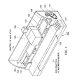
- a recording medium 106 set to a paper feed position in the recording apparatus 100 is advanced by a feed roller 109 to an area where printing can be made with an ink jet cartridge 103.
- a platen 108 is provided to position in contact with the back side of the recording medium in the printing-enable area.
- a carriage 101 is constructed to be movable in a certain direction with cooperation of a guide shaft 104 and a guide unit 105.
- the movement of the carriage 101 renders the ink jet cartridge 103 to reciprocally scan over the printing-enable area in the direction of main scan.
- the carriage 101 mounts thereon the ink jet cartridge 103 which includes an ink jet head element capable of ejecting inks of multiple colors, an ink jet head element capable of ejecting a processing liquid reacting with the inks to make color materials in the inks insoluble, and ink tanks for supplying the inks and the treatment liquid to the corresponding elements of an ink jet head 102.
- the guide shaft 104 is an eccentric shaft, and a gear 120 is attached to the guide shaft 104.
- a gear 120 is rotated by a head-to-paper gap control motor (not shown) through a transmission belt 121 and a gear 121.
- the restoration system unit 110 can discharge the ink having increased viscosity from ejection orifices of the ink jet head at the start of recording, and can close the ejection orifices of the ink jet head by a cap member during a period of non-recording so that an ink solvent is kept from evaporating through the ejection orifices.
- a control panel 107 comprises a switch section and an indicator section.
- the switch section is manipulated, for example, when turning on/off power of the ink jet recording apparatus, and setting various recording modes.
- the indicator section serves to indicate various status conditions of the recording apparatus.
- the ink jet head 102 comprises two head elements 200Bk1 (nozzle line Bk1) and 200Bk2 (nozzle line Bk2) for ejecting a black ink K, and one head element 200S (nozzle line S) for ejecting a processing liquid S.
- Those head elements are arranged on a frame 204 with a 1/2-inch pitch in the direction of main scan.
- Fig. 3 is a block diagram showing one example of a control system for the ink jet recording apparatus having the above-described construction.
- numeral 1010 denotes a control unit including control means for controlling a gap between the ejection surface of the recording head and the recording medium depending on the type of the recording medium
- 1000 denotes an MPU for controlling various components
- 1001 denotes a ROM for storing a program, etc. corresponding to control procedures executed by the MPU
- 1002 denotes a RAM serving as a work area for use in execution of the control procedures.
- the control unit 1010 is connected to the control panel 107 and a printer unit 23 through an interface 1003. Control signals outputted from the control unit 1010 are used to drive a restoration system unit 1, a recording head 6 through a head driver 25, a carriage motor 10 through a motor driver 27, and a head-to-paper gap control motor 29.
- step S1 if it is determined in step S1 that the recording medium is ordinary paper, the control unit goes to step S2 to determine whether the mode is a one-pass recording mode for high-speed recording or a multi-pass recording mode for high-quality recording. Whether the recording is to be made in the one-pass recording mode or the multi-pass recording mode is set by an operator manipulating the control panel 107. If the mode is the one-pass recording mode, the control unit goes to step S3 in which the head-to-paper gap control motor 29 is driven to set the head-to-paper gap to 1.5 mm.
- step S5 it is determined whether the recording medium is a film medium such as a calendered film or an OHP film, or specific recording paper such as coated paper or calendered paper.
- the recording medium does not elongate upon application of the ink, and therefore hardly cockles.
- a sheet of specific recording paper cockles but in a smaller amount than ordinary paper.
- step S5 determines whether the recording medium is susceptible to cockling or not, i.e., whether the recording medium is apt to easily elongate or not upon application of the ink.
- step S5 If it is determined in step S5 that the recording medium is a film medium (YES in step S5), the control unit goes to step S7 in which the head-to-paper gap control motor 29 is driven to adjust the head-to-paper gap to 0.5 mm. If the recording medium is specific recording paper (NO in step S5), the control unit goes to step S6 in which the head-to-paper gap is adjusted to 0.8 mm, taking into account cockling of the specific recording paper.
- the printer when a printer is used, the printer is connected to a personal computer and a recording mode is set by a printer driver built in the personal computer. It is therefore most desirable that the head-to-paper gap control be performed by determining on the printer side the type of a signal corresponding to the recording mode selected by the printer driver. For a printer capable of changing the recording mode upon manipulation of a switch section of a printer control panel as described above, however, the head-to-paper gap control is performed by a printer control unit which determines the recording mode selected through the switch section.
- the present invention is particularly advantageous when applied, among various ink jet recording systems, to an ink jet recording head and apparatus of the type that flying ink droplets are formed by utilizing thermal energy to carry out recording.
- the on-demand type is more advantageous in that electro-thermal transducers are arranged corresponding to sheets and liquid passages holding a liquid (ink), and at least one driving signal which corresponds to recording information and provides such a quick temperature rise as exceeding a level required to cause seed boiling is applied to the electro-thermal transducer to generate thermal energy in the transducer, whereby film boiling is caused in a heat acting surface of a recording head so that a bubble can be formed in the liquid (ink) corresponding to the driving signal in one-to-one relation.
- the liquid (ink) is ejected through an ejection orifice in the form of at least one droplet.
- the driving signal is applied in the form of a pulse because using a pulse signal enables a bubble to properly grow and shrink in an instant, and can achieve ejection of the liquid (ink) superior especially in response.
- the pulse-like driving signal is suitably produced as disclosed in US Patent No. 4,463,359 and No. 4,345,262. More superior recording can be achieved by employing the conditions for a temperature rising rate in the heat acting surface which are disclosed in US Patent No. 4,313,124.
- the recording head can be constructed by combining ejection orifices, liquid passages, and electro-thermal transducers (to form linear or right-angled liquid passages) as disclosed in the above-cited US Patents.
- the recording head may be constructed such that the heat acting portion is arranged in a curved area, as disclosed in US Patent No. 4,558,333 and No. 4,459,600.
- the recording head is provided with a restoration means, a preliminary auxiliary means, etc. from the standpoint of providing the advantages or the present invention with higher stability. Specifically, it is effective in achieving stable recording to provide a capping means, a cleaning means, a pressurizing or sucking means, and a preliminary heating means using the electro-thermal transducers or other heating elements or a combination thereof, and to perform a preliminary ejection mode to eject ink separately from recording.
- the ink may be solidified at the room temperature or above, and then softened or liquefied at the room temperature.
- it is general in the above-described ink jet recording system to perform temperature control such that the temperature of ink itself is adjusted to fall in the range of 30°C to 70°C to hold the viscosity of the ink within an ejection stable range.
- the ink is therefore just required to be in a liquid state when a recording signal is applied to the head in use.
- the most effective recording system is to implement ejection of the ink in accordance with the above-mentioned film boiling method.
- the head-to-paper gap can be set to be very narrow and better image quality than conventionally achieved can be ensured.
Landscapes
- Ink Jet (AREA)
- Common Mechanisms (AREA)
- Particle Formation And Scattering Control In Inkjet Printers (AREA)
Applications Claiming Priority (2)
| Application Number | Priority Date | Filing Date | Title |
|---|---|---|---|
| JP18404398 | 1998-06-30 | ||
| JP18404398A JP3667096B2 (ja) | 1998-06-30 | 1998-06-30 | インクジェット記録装置及びインクジェット記録方法 |
Publications (3)
| Publication Number | Publication Date |
|---|---|
| EP0970816A2 true EP0970816A2 (fr) | 2000-01-12 |
| EP0970816A3 EP0970816A3 (fr) | 2000-06-07 |
| EP0970816B1 EP0970816B1 (fr) | 2005-05-18 |
Family
ID=16146370
Family Applications (1)
| Application Number | Title | Priority Date | Filing Date |
|---|---|---|---|
| EP99305118A Expired - Lifetime EP0970816B1 (fr) | 1998-06-30 | 1999-06-29 | Appareil et procédé d' impression à jet d'encre |
Country Status (4)
| Country | Link |
|---|---|
| US (1) | US6273536B1 (fr) |
| EP (1) | EP0970816B1 (fr) |
| JP (1) | JP3667096B2 (fr) |
| DE (1) | DE69925335T2 (fr) |
Cited By (3)
| Publication number | Priority date | Publication date | Assignee | Title |
|---|---|---|---|---|
| EP1199170A3 (fr) * | 2000-10-17 | 2002-09-11 | Seiko Epson Corporation | Dispositif d'enregistrement à jet d'encre |
| EP1208989A3 (fr) * | 2000-11-17 | 2003-10-22 | Canon Kabushiki Kaisha | Appareil et procédé d'impression à jet d'encre |
| EP1208990A3 (fr) * | 2000-11-17 | 2004-02-04 | Canon Kabushiki Kaisha | Appareil d'impression à jet d'encre |
Families Citing this family (14)
| Publication number | Priority date | Publication date | Assignee | Title |
|---|---|---|---|---|
| JP2002001928A (ja) | 2000-06-21 | 2002-01-08 | Canon Inc | 記録装置 |
| JP2002154200A (ja) * | 2000-11-20 | 2002-05-28 | Canon Inc | 画像形成装置 |
| JP4058913B2 (ja) * | 2001-03-30 | 2008-03-12 | セイコーエプソン株式会社 | 印刷媒体の変形を考慮した印刷 |
| US6666537B1 (en) * | 2002-07-12 | 2003-12-23 | Hewlett-Packard Development Company, L.P. | Pen to paper spacing for inkjet printing |
| JP4497825B2 (ja) * | 2003-03-10 | 2010-07-07 | キヤノン株式会社 | インクジェット記録方法及びインクジェット記録装置 |
| US7481527B2 (en) * | 2004-02-17 | 2009-01-27 | Seiko Epson Corporation | Liquid ejection apparatus |
| JP4509706B2 (ja) * | 2004-09-08 | 2010-07-21 | Sriスポーツ株式会社 | ゴルフボール用マーキング装置及びゴルフボールのマーキング方法 |
| US7591527B2 (en) * | 2005-07-08 | 2009-09-22 | Canon Kabushiki Kaisha | Ink jet printing head |
| US7445302B2 (en) * | 2005-09-21 | 2008-11-04 | Lexmark International, Inc | Method for determining a printhead gap in an ink jet apparatus that performs bi-directional alignment of the printhead |
| JP4747999B2 (ja) * | 2006-08-30 | 2011-08-17 | 富士ゼロックス株式会社 | 画像処理装置及び液滴吐出装置 |
| US8061791B2 (en) * | 2007-03-07 | 2011-11-22 | Xerox Corporation | Dual printer for regular and raised print |
| US8646861B2 (en) * | 2007-07-13 | 2014-02-11 | Canon Kabushiki Kaisha | Printing apparatus, printing system, and control method for the same system |
| JP5845768B2 (ja) * | 2010-09-28 | 2016-01-20 | ブラザー工業株式会社 | 液体吐出装置 |
| JP5850667B2 (ja) * | 2011-08-03 | 2016-02-03 | キヤノン株式会社 | インクジェット記録装置およびインクジェット記録方法 |
Citations (7)
| Publication number | Priority date | Publication date | Assignee | Title |
|---|---|---|---|---|
| US4313124A (en) | 1979-05-18 | 1982-01-26 | Canon Kabushiki Kaisha | Liquid jet recording process and liquid jet recording head |
| US4345262A (en) | 1979-02-19 | 1982-08-17 | Canon Kabushiki Kaisha | Ink jet recording method |
| US4459600A (en) | 1978-10-31 | 1984-07-10 | Canon Kabushiki Kaisha | Liquid jet recording device |
| US4463359A (en) | 1979-04-02 | 1984-07-31 | Canon Kabushiki Kaisha | Droplet generating method and apparatus thereof |
| US4558333A (en) | 1981-07-09 | 1985-12-10 | Canon Kabushiki Kaisha | Liquid jet recording head |
| US4723129A (en) | 1977-10-03 | 1988-02-02 | Canon Kabushiki Kaisha | Bubble jet recording method and apparatus in which a heating element generates bubbles in a liquid flow path to project droplets |
| JPH09216354A (ja) | 1996-02-13 | 1997-08-19 | Canon Inc | インクジェットプリント装置、ヘッドユニットおよびインクジェットカートリッジ |
Family Cites Families (13)
| Publication number | Priority date | Publication date | Assignee | Title |
|---|---|---|---|---|
| JPS5936879B2 (ja) | 1977-10-14 | 1984-09-06 | キヤノン株式会社 | 熱転写記録用媒体 |
| JPS59123670A (ja) | 1982-12-28 | 1984-07-17 | Canon Inc | インクジエツトヘツド |
| JPS59138461A (ja) | 1983-01-28 | 1984-08-08 | Canon Inc | 液体噴射記録装置 |
| DE3332491C2 (de) | 1983-09-08 | 1985-10-10 | Siemens AG, 1000 Berlin und 8000 München | Vorrichtung für Tintenschreibeinrichtungen zum Beschreiben eines Aufzeichnungsträgers |
| JPS6071260A (ja) | 1983-09-28 | 1985-04-23 | Erumu:Kk | 記録装置 |
| JP3025778B2 (ja) | 1988-04-08 | 2000-03-27 | レックスマーク・インターナショナル・インコーポレーテッド | 印刷ヘツドの間隙調節機能付きのプリンタ |
| EP0479270B1 (fr) | 1990-10-03 | 1996-05-22 | Canon Kabushiki Kaisha | Appareil d'enregistrement |
| JPH04355177A (ja) * | 1991-05-31 | 1992-12-09 | Brother Ind Ltd | 印字ヘッドのギャップ調整装置 |
| EP0650846B1 (fr) * | 1993-10-29 | 1998-12-09 | Hewlett-Packard Company | Commande auto-ajustable de l'espace entre la tête d'impression et le support d'enregistrement dans les imprimantes par jet d'encre |
| US5366301A (en) | 1993-12-14 | 1994-11-22 | Hewlett-Packard Company | Record media gap adjustment system for use in printers |
| CA2155505C (fr) * | 1994-08-10 | 2000-05-16 | Jiro Moriyama | Procede et dispositif d'impression a jet d'encre |
| US5852452A (en) * | 1996-07-25 | 1998-12-22 | Brother Kogyo Kabushiki Kaisha | Ink jet printer with adjustable capping mechanism and printing cap |
| JPH10128959A (ja) * | 1996-10-30 | 1998-05-19 | Canon Inc | 記録装置 |
-
1998
- 1998-06-30 JP JP18404398A patent/JP3667096B2/ja not_active Expired - Fee Related
-
1999
- 1999-06-29 US US09/342,190 patent/US6273536B1/en not_active Expired - Lifetime
- 1999-06-29 DE DE69925335T patent/DE69925335T2/de not_active Expired - Lifetime
- 1999-06-29 EP EP99305118A patent/EP0970816B1/fr not_active Expired - Lifetime
Patent Citations (8)
| Publication number | Priority date | Publication date | Assignee | Title |
|---|---|---|---|---|
| US4723129A (en) | 1977-10-03 | 1988-02-02 | Canon Kabushiki Kaisha | Bubble jet recording method and apparatus in which a heating element generates bubbles in a liquid flow path to project droplets |
| US4740796A (en) | 1977-10-03 | 1988-04-26 | Canon Kabushiki Kaisha | Bubble jet recording method and apparatus in which a heating element generates bubbles in multiple liquid flow paths to project droplets |
| US4459600A (en) | 1978-10-31 | 1984-07-10 | Canon Kabushiki Kaisha | Liquid jet recording device |
| US4345262A (en) | 1979-02-19 | 1982-08-17 | Canon Kabushiki Kaisha | Ink jet recording method |
| US4463359A (en) | 1979-04-02 | 1984-07-31 | Canon Kabushiki Kaisha | Droplet generating method and apparatus thereof |
| US4313124A (en) | 1979-05-18 | 1982-01-26 | Canon Kabushiki Kaisha | Liquid jet recording process and liquid jet recording head |
| US4558333A (en) | 1981-07-09 | 1985-12-10 | Canon Kabushiki Kaisha | Liquid jet recording head |
| JPH09216354A (ja) | 1996-02-13 | 1997-08-19 | Canon Inc | インクジェットプリント装置、ヘッドユニットおよびインクジェットカートリッジ |
Cited By (6)
| Publication number | Priority date | Publication date | Assignee | Title |
|---|---|---|---|---|
| EP1199170A3 (fr) * | 2000-10-17 | 2002-09-11 | Seiko Epson Corporation | Dispositif d'enregistrement à jet d'encre |
| US6733102B2 (en) | 2000-10-17 | 2004-05-11 | Seiko Epson Corporation | Ink jet recording apparatus |
| EP1208989A3 (fr) * | 2000-11-17 | 2003-10-22 | Canon Kabushiki Kaisha | Appareil et procédé d'impression à jet d'encre |
| EP1208990A3 (fr) * | 2000-11-17 | 2004-02-04 | Canon Kabushiki Kaisha | Appareil d'impression à jet d'encre |
| US6945628B2 (en) | 2000-11-17 | 2005-09-20 | Canon Kabushiki Kaisha | Ink jet printing apparatus |
| EP2116381A3 (fr) * | 2000-11-17 | 2010-05-05 | Canon Kabushiki Kaisha | Appareil d'impression à jet d'encre |
Also Published As
| Publication number | Publication date |
|---|---|
| JP3667096B2 (ja) | 2005-07-06 |
| US6273536B1 (en) | 2001-08-14 |
| EP0970816B1 (fr) | 2005-05-18 |
| EP0970816A3 (fr) | 2000-06-07 |
| JP2000015788A (ja) | 2000-01-18 |
| DE69925335T2 (de) | 2006-01-19 |
| DE69925335D1 (de) | 2005-06-23 |
Similar Documents
| Publication | Publication Date | Title |
|---|---|---|
| US6273536B1 (en) | Ink jet recording apparatus | |
| EP0802060B1 (fr) | Méthode et appareil d'impression à jet d'encre utilisant une liquide améliorant la qualité d'impression | |
| EP0517468B1 (fr) | Méthode et dispositif d'enregistrement à jet d'encre | |
| US6231156B1 (en) | Ink-jet printing apparatus and ejection recovery method of printing head | |
| JP3313963B2 (ja) | インクジェットプリント方法およびプリント装置 | |
| KR0136737B1 (ko) | 상이한 특성의 잉크를 사용한 잉크제트기록방법과 그 장치 | |
| US6299285B1 (en) | Ink-jet printing apparatus and ink-jet printing method | |
| JP3320317B2 (ja) | インクジェットプリント装置およびプリント方法 | |
| EP0788885B1 (fr) | Appareil d'impression à jet d'encre et méthode d'impression | |
| JP3313977B2 (ja) | インクジェット記録方法およびインクジェット記録装置 | |
| EP0847872B1 (fr) | Méthode pour l'impression par jet d'encre utilisant un premier et un deuxième liquide, et un appareil pour cette méthode | |
| JP3843573B2 (ja) | インクジェット記録方法 | |
| JP3408108B2 (ja) | インクジェットプリント方法およびインクジェットプリント装置 | |
| JPH1111000A (ja) | インクジェット記録方法およびインクジェット記録装置 | |
| EP0858896B1 (fr) | Dispositif d'impression à jet d'encre et procédé d'impression utilisant cette dispositif | |
| JP2005225114A (ja) | インクジェット記録方法、プリンタドライバ及びインクジェット記録装置 | |
| US6126282A (en) | Ink-jet recording apparatus and method thereof | |
| JP3697046B2 (ja) | 画像形成方法および画像形成装置 | |
| JPH10128959A (ja) | 記録装置 | |
| JP2001138554A (ja) | インクジェット記録方法およびインクジェット記録装置 | |
| JP2005007578A (ja) | インクジェット記録方法及びインクジェット記録装置 | |
| JPH10278242A (ja) | インクジェット記録装置 | |
| JP3437200B2 (ja) | カラーインクジェット記録方法 | |
| JP3226754B2 (ja) | インクジェットプリント装置およびインクジェットプリント方法 | |
| JPH10226088A (ja) | インクジェット記録装置および記録ヘッドの吐出回復処理方法 |
Legal Events
| Date | Code | Title | Description |
|---|---|---|---|
| PUAI | Public reference made under article 153(3) epc to a published international application that has entered the european phase |
Free format text: ORIGINAL CODE: 0009012 |
|
| AK | Designated contracting states |
Kind code of ref document: A2 Designated state(s): DE ES FR GB IT NL |
|
| AX | Request for extension of the european patent |
Free format text: AL;LT;LV;MK;RO;SI |
|
| PUAL | Search report despatched |
Free format text: ORIGINAL CODE: 0009013 |
|
| AK | Designated contracting states |
Kind code of ref document: A3 Designated state(s): AT BE CH CY DE DK ES FI FR GB GR IE IT LI LU MC NL PT SE |
|
| AX | Request for extension of the european patent |
Free format text: AL;LT;LV;MK;RO;SI |
|
| RIC1 | Information provided on ipc code assigned before grant |
Free format text: 7B 41J 2/21 A, 7B 41J 25/308 B |
|
| 17P | Request for examination filed |
Effective date: 20001113 |
|
| AKX | Designation fees paid |
Free format text: DE ES FR GB IT NL |
|
| 17Q | First examination report despatched |
Effective date: 20031105 |
|
| RTI1 | Title (correction) |
Free format text: INK JET RECORDING APPARATUS AND METHOD |
|
| GRAP | Despatch of communication of intention to grant a patent |
Free format text: ORIGINAL CODE: EPIDOSNIGR1 |
|
| GRAS | Grant fee paid |
Free format text: ORIGINAL CODE: EPIDOSNIGR3 |
|
| GRAA | (expected) grant |
Free format text: ORIGINAL CODE: 0009210 |
|
| AK | Designated contracting states |
Kind code of ref document: B1 Designated state(s): DE ES FR GB IT NL |
|
| PG25 | Lapsed in a contracting state [announced via postgrant information from national office to epo] |
Ref country code: NL Free format text: LAPSE BECAUSE OF FAILURE TO SUBMIT A TRANSLATION OF THE DESCRIPTION OR TO PAY THE FEE WITHIN THE PRESCRIBED TIME-LIMIT Effective date: 20050518 Ref country code: IT Free format text: LAPSE BECAUSE OF FAILURE TO SUBMIT A TRANSLATION OF THE DESCRIPTION OR TO PAY THE FEE WITHIN THE PRESCRIBED TIME-LIMIT;WARNING: LAPSES OF ITALIAN PATENTS WITH EFFECTIVE DATE BEFORE 2007 MAY HAVE OCCURRED AT ANY TIME BEFORE 2007. THE CORRECT EFFECTIVE DATE MAY BE DIFFERENT FROM THE ONE RECORDED. Effective date: 20050518 |
|
| REG | Reference to a national code |
Ref country code: GB Ref legal event code: FG4D |
|
| REF | Corresponds to: |
Ref document number: 69925335 Country of ref document: DE Date of ref document: 20050623 Kind code of ref document: P |
|
| PG25 | Lapsed in a contracting state [announced via postgrant information from national office to epo] |
Ref country code: ES Free format text: LAPSE BECAUSE OF FAILURE TO SUBMIT A TRANSLATION OF THE DESCRIPTION OR TO PAY THE FEE WITHIN THE PRESCRIBED TIME-LIMIT Effective date: 20050829 |
|
| NLV1 | Nl: lapsed or annulled due to failure to fulfill the requirements of art. 29p and 29m of the patents act | ||
| PLBE | No opposition filed within time limit |
Free format text: ORIGINAL CODE: 0009261 |
|
| STAA | Information on the status of an ep patent application or granted ep patent |
Free format text: STATUS: NO OPPOSITION FILED WITHIN TIME LIMIT |
|
| 26N | No opposition filed |
Effective date: 20060221 |
|
| EN | Fr: translation not filed | ||
| PG25 | Lapsed in a contracting state [announced via postgrant information from national office to epo] |
Ref country code: FR Free format text: LAPSE BECAUSE OF NON-PAYMENT OF DUE FEES Effective date: 20050630 |
|
| PG25 | Lapsed in a contracting state [announced via postgrant information from national office to epo] |
Ref country code: FR Free format text: LAPSE BECAUSE OF NON-PAYMENT OF DUE FEES Effective date: 20050518 |
|
| PGFP | Annual fee paid to national office [announced via postgrant information from national office to epo] |
Ref country code: GB Payment date: 20150626 Year of fee payment: 17 Ref country code: DE Payment date: 20150630 Year of fee payment: 17 |
|
| REG | Reference to a national code |
Ref country code: DE Ref legal event code: R119 Ref document number: 69925335 Country of ref document: DE |
|
| GBPC | Gb: european patent ceased through non-payment of renewal fee |
Effective date: 20160629 |
|
| PG25 | Lapsed in a contracting state [announced via postgrant information from national office to epo] |
Ref country code: DE Free format text: LAPSE BECAUSE OF NON-PAYMENT OF DUE FEES Effective date: 20170103 |
|
| PG25 | Lapsed in a contracting state [announced via postgrant information from national office to epo] |
Ref country code: GB Free format text: LAPSE BECAUSE OF NON-PAYMENT OF DUE FEES Effective date: 20160629 |