EP0970839A1 - Vorrichtung zur Umsetzung zumindest einer Fussbedienung eines Fahrzeuges in Handbedienung - Google Patents
Vorrichtung zur Umsetzung zumindest einer Fussbedienung eines Fahrzeuges in Handbedienung Download PDFInfo
- Publication number
- EP0970839A1 EP0970839A1 EP99390013A EP99390013A EP0970839A1 EP 0970839 A1 EP0970839 A1 EP 0970839A1 EP 99390013 A EP99390013 A EP 99390013A EP 99390013 A EP99390013 A EP 99390013A EP 0970839 A1 EP0970839 A1 EP 0970839A1
- Authority
- EP
- European Patent Office
- Prior art keywords
- control device
- cable
- hand control
- housing
- foot
- Prior art date
- Legal status (The legal status is an assumption and is not a legal conclusion. Google has not performed a legal analysis and makes no representation as to the accuracy of the status listed.)
- Withdrawn
Links
- 230000001131 transforming effect Effects 0.000 title description 2
- 230000005540 biological transmission Effects 0.000 claims abstract description 20
- 238000005452 bending Methods 0.000 claims description 12
- 230000001133 acceleration Effects 0.000 claims description 7
- 238000000926 separation method Methods 0.000 claims description 7
- 238000006073 displacement reaction Methods 0.000 claims description 5
- 239000000463 material Substances 0.000 claims description 3
- 230000007935 neutral effect Effects 0.000 claims description 3
- 230000002093 peripheral effect Effects 0.000 claims description 2
- 238000007373 indentation Methods 0.000 claims 1
- 230000035515 penetration Effects 0.000 claims 1
- 230000000694 effects Effects 0.000 description 7
- 239000003292 glue Substances 0.000 description 4
- 238000004026 adhesive bonding Methods 0.000 description 3
- 238000003780 insertion Methods 0.000 description 3
- 230000037431 insertion Effects 0.000 description 3
- 210000000056 organ Anatomy 0.000 description 3
- 241000309551 Arthraxon hispidus Species 0.000 description 2
- 239000004020 conductor Substances 0.000 description 1
- 238000005553 drilling Methods 0.000 description 1
- 238000009434 installation Methods 0.000 description 1
- 210000003141 lower extremity Anatomy 0.000 description 1
- 230000002040 relaxant effect Effects 0.000 description 1
- 238000007665 sagging Methods 0.000 description 1
Images


Classifications
-
- B—PERFORMING OPERATIONS; TRANSPORTING
- B60—VEHICLES IN GENERAL
- B60W—CONJOINT CONTROL OF VEHICLE SUB-UNITS OF DIFFERENT TYPE OR DIFFERENT FUNCTION; CONTROL SYSTEMS SPECIALLY ADAPTED FOR HYBRID VEHICLES; ROAD VEHICLE DRIVE CONTROL SYSTEMS FOR PURPOSES NOT RELATED TO THE CONTROL OF A PARTICULAR SUB-UNIT
- B60W30/00—Purposes of road vehicle drive control systems not related to the control of a particular sub-unit, e.g. of systems using conjoint control of vehicle sub-units
- B60W30/18—Propelling the vehicle
-
- B—PERFORMING OPERATIONS; TRANSPORTING
- B60—VEHICLES IN GENERAL
- B60W—CONJOINT CONTROL OF VEHICLE SUB-UNITS OF DIFFERENT TYPE OR DIFFERENT FUNCTION; CONTROL SYSTEMS SPECIALLY ADAPTED FOR HYBRID VEHICLES; ROAD VEHICLE DRIVE CONTROL SYSTEMS FOR PURPOSES NOT RELATED TO THE CONTROL OF A PARTICULAR SUB-UNIT
- B60W2710/00—Output or target parameters relating to a particular sub-units
- B60W2710/02—Clutches
-
- B—PERFORMING OPERATIONS; TRANSPORTING
- B60—VEHICLES IN GENERAL
- B60W—CONJOINT CONTROL OF VEHICLE SUB-UNITS OF DIFFERENT TYPE OR DIFFERENT FUNCTION; CONTROL SYSTEMS SPECIALLY ADAPTED FOR HYBRID VEHICLES; ROAD VEHICLE DRIVE CONTROL SYSTEMS FOR PURPOSES NOT RELATED TO THE CONTROL OF A PARTICULAR SUB-UNIT
- B60W2710/00—Output or target parameters relating to a particular sub-units
- B60W2710/06—Combustion engines, Gas turbines
-
- B—PERFORMING OPERATIONS; TRANSPORTING
- B60—VEHICLES IN GENERAL
- B60W—CONJOINT CONTROL OF VEHICLE SUB-UNITS OF DIFFERENT TYPE OR DIFFERENT FUNCTION; CONTROL SYSTEMS SPECIALLY ADAPTED FOR HYBRID VEHICLES; ROAD VEHICLE DRIVE CONTROL SYSTEMS FOR PURPOSES NOT RELATED TO THE CONTROL OF A PARTICULAR SUB-UNIT
- B60W2710/00—Output or target parameters relating to a particular sub-units
- B60W2710/18—Braking system
Definitions
- the present invention relates to a device intended to be fixed or integrated into a steering wheel and comprising the brake and / or gas and / or clutch and / or change of speed of this vehicle, this device being mainly intended to equip vehicles for people deprived of the use of their legs.
- cable non-deformable in torsion means a cable whose elastic torsional deformation, between two sections distant from each other by a few tens of centimeters under the effect of a couple of high value, remains insignificant.
- cable should be understood to mean any elongated elastically deformable element. in bending and non-deformable in torsion according to the preceding definition.
- a control device consisting of a steering wheel comprising a rigid part forming a carrying core.
- This rigid part is arranged in a flexible sheath which can rotate around the axis of the carrying core.
- transmission levers are fixed which are also fixed to traction members acting on the accelerator pedal.
- Document EP-A-69 090 shows an apparatus for transforming the foot control of the accelerator of a vehicle in hand control.
- This device like the one described in the DE-A-2 333 546 comprises a fixed part in the form of a torus and a mobile part in the form of sheath mounted on the fixed part with the possibility of turning relative to the fixed part.
- a mechanism with transmission levers to which a push-button mechanism connected to the accelerator pedal.
- the movement transmission lever mechanism is secured.
- the support collar is secured the pusher mechanism.
- Document EP-A-114 673 shows an acceleration control device for the disabled of the lower limbs.
- the steering wheel is associated with a hand wheel, this hand wheel is fixedly mounted in rotation relative to the steering wheel and movable in translation along the axis of the steering column.
- To this wheel are attached two transmission rods integral with a ring mounted fixed axially with respect to the steering wheel to actuate an acceleration device by means of a ring 12 mounted around the steering sleeve.
- Document EP-A-647,540 shows a device for actuating the accelerator of an automobile by drivers deprived of the use of their legs.
- This device comprises a control wheel mounted fixed in rotation relative to the driving wheel but free in axial translation relative to the latter for actuating a movement transmission connected to the accelerator pedal.
- This movement transmission comprises a collar mounted around the steering sleeve. This collar is guided in translation by guide rods integral with the spokes of the steering wheel and is fixed to rods integral with the steering wheel or the control ring.
- the drawback of the device described in the aforementioned document lies essentially in the fact of the need to space the levers to allow their pivoting. For this reason, the device cannot have a uniform and continuous actuation surface and this results in a risk of fingers pinching between two levers during actuation.
- the levers in rest position are parallel to the plane of the steering wheel and overlap with respect to said steering wheel. This provision can make it difficult to grip the steering wheel and can partially or entirely hide the vehicle's on-board instruments.
- the present invention aims to overcome the drawbacks mentioned above in using a device intended to be fixed to the circumferential element of the steering wheel management or integrated into it.
- the hand control device intended to be fixed to one of the elements of steering of a motor vehicle and comprising means for controlling the acceleration of the vehicle and / or braking control means and / or brake control means clutching and disengaging the gearbox and / or the change control means speed, is essentially characterized in that it comprises a first element, in which is hollowed out at least one continuous groove constituting housing for at least one cable deformable in bending and non-deformable in torsion to which are rigidly fixed apart one from the other, several transmission levers each comprising opposite the cable, externally to the groove, a joint head, the levers by their joint head being secured to at least one second element, mounted coaxially with respect to the first element, the two said elements being mounted relative to each other in a fixed manner in rotation and movable in translation along their geometric axes of revolution, towards each other and inversely away from each other, between an extreme position of separation and a extreme insertion position, one of the said elements being intended to be fixed to one of the steering elements and
- This arrangement provides a continuous actuation surface without elements likely to hide the dashboard of the vehicle.
- the electrical signal delivered by the sensor is used for the control of acceleration.
- the driving-in movement of the two elements with respect to each other takes place against a restoring force towards the position extreme spacing.
- the latter under the effect of the restoring force returns itself in position extreme separation which results in deceleration of the vehicle.
- the transmission cable is mounted in the housing with the possibility of pivoting on itself around its longitudinal axis. Its torsional non-deformability allows pushing the two elements towards each other to transmit to all the levers the same pivoting movement and ensuring the displacement of the two said elements according to a translation and whether the resulting force which generates their relative displacement is offset or not.
- each lever comprises a foot by which it is rigidly fixed to at least one transmission cable, and by which it is mounted in a seat practiced in the groove and preferably forming a hollow imprint in the latter.
- the foot of each lever is provided with at least one housing in which at least one transmission cable is engaged, the portion of cable located in the housing being immobilized relative to the latter without possibility of axial movement, rotation movement around its axis, movement of pivoting and bending so that during the driving-in movement of the two elements towards each other, bending forces may appear in the cable, these bending forces being at the origin of the recall effort.
- the restoring force is generated by at least an elastic return member interposed between the two elements.
- the organ elastic return consists of a coil spring and parallel to the geometric axis of revolution
- the first element is provided with a protruding pin around which the organ is engaged elastic return, said member being moreover engaged in a form of shaped socket in the second element.
- the hand control device 1 is intended for be attached to one of the steering elements of a motor vehicle, for example the steering wheel 2 of direction.
- the device can also be attached to the steering column and, in this case, it replaces at the steering wheel.
- this device 1 integrates the commands for the accelerator and the brake controls, it can also integrate the clutch and disengage as well as possibly the gear change in case the vehicle would not be equipped with an automatic gearbox.
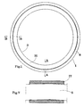
- the control device comprises a first element 3 substantially in the form of a circular ring, in which a continuous groove 4 is hollowed out following the outline of a circle and presenting a rounded bottom.
- a cable 5 deformable in bending and undeformable in torsion.
- This cable has a diameter less than the depth of the groove and its length is such that the ends of the latter, after installation in the groove 4 are separated one of the other a few millimeters.
- the diameter of the cable is substantially equal to the width throat 4.
- Each lever 6 comprises a tubular foot 17, of cylindrical external surface, having along its longitudinal axis, a through housing of circular cross section, in which engages the cable 5.
- the lever 6 is rigidly fixed to the cable 5 by its foot 17 as described later.
- the levers 6, by their articulation head 7, are secured to a second element 8 substantially in the form of a circular ring, mounted coaxially around the first element 3.
- the head 7 of each lever, while being integral with the second element, is mounted so as to ability to move radially relative to the latter.
- each lever 6 consists of two axially aligned axially opposite pivots 7a, of cylindrical shape and the second actuating element comprises, opposite the first element 3, a plurality of slides 8a regularly spaced, in each of which engages in sliding the head 7 of a lever 6 and only one.
- the two elements 3, 8 are mounted relative to each other in a fixed manner in rotation and movable in translation between an extreme spacing position and an extreme position and vice versa and only along their geometric axes of revolution.
- this restoring force being mainly generated by an elastic member return 11 interposed between the two elements 3, 8 and constituted by a coil spring.
- this coil spring 11 is engaged around a projecting pin 12 for holding and centering, arranged parallel to the geometric axis of revolution.
- the organ elastic 11 and the pin 12 are engaged in a form of socket 13 formed in the second element 8.
- several elastic members and several regularly distributed salient pawns are provided.
- the first element 3 is fixed by hooks 9 to the steering wheel 4 and occupies a fixed position relative to the latter
- the second element 8 movable in translation relative to the steering wheel and to the first element is intended to be operated by the driver for actuation of one of the vehicle's controls, for example without being limiting, the accelerator.
- an electrical sensor 10 is mechanically interposed between the two elements 3, 8 for delivering an electrical signal of value representative of their relative position relative to each other.
- the first element 3 is intended to be operated by the conductor for actuating the electrical sensor 10 and the second element 8 is fixed to the steering wheel or well to the steering column and in this case constitutes the body of the steering wheel.
- the first element 3 comprises on the one hand a base 14 in the form of a circular crown comprising an inner circumferential rim and a outer circumferential rim and on the other hand two endless walls one internal 15 the other external 16, both projecting from the base 14, arranged concentrically apart one of the other and forming the groove 4 of the cable 5.
- the internal wall 15 is located in the extension of the inner circumferential rim of the circular crown and the outer wall 16 is disposed apart from the outer circumferential rim. According to this provision, the pawn of centering 12 protrudes from the surface in a circular ring located between the endless wall outer 16 and the outer circumferential rim of the base 14.
- each seat 18 is formed by a hollow imprint dug in the back of the throat. This imprint appears as a portion of cylindrical surface.
- the foot of each lever fits into the corresponding seat to be perfectly guided in rotation when the lever is pivoted. Through elsewhere this nesting prevents movement of the foot along the circumference of the throat which ensures precise positioning of the cable in its housing.
- the groove 4 is covered with an annular wall 19 coming into contact or at very low distance from the foot 17 of each lever 6 in order to keep the foot 17 in its seat 18.
- This annular wall 19 is provided with several radial notches 20 made towards the center from its external peripheral rim, in each of which a lever 6 engages. correspondence with each notch of the annular covering wall 19, the wall external endless 16 has a notch 16a in which the corresponding lever engages during the driving-in movement of the two elements 3, 8 one inside the other.
- Each lever 6, in position of maximum separation of the second element relative to the first abuts against the bottom of the corresponding notch 20 which limits the spacing trajectory of the two elements relative to each other.
- the annular wall is fixed by gluing against the edges of the internal 15 and external 16 endless walls.
- the second element 8 is formed by two rims cylindrical of unequal widths and the same thickness, one internal 21 and the other external 22, arranged concentrically one inside the other, and joined to each other by a connecting wall 23 of semi toroidal shape, the rim 21 of small width being the internal rim.
- the outer surface of the semi-toric wall constitutes the continuous actuation surface on which the user applies the driving force.
- This second element is arranged around the external wall without end 16 of the first element and evolves in translation to the right of the surface in a circular crown delimited by the outer edge of the base 14 and the outer wall.
- the slides 8a, in which slide the heads 7 of the levers 6, extend radially from the free edge of the rim of small width towards the rim of large width.
- each slide is consisting of two parallel rails 24 arranged at a distance from each other and each formed of two parallel wings joined to one another along one of their longitudinal edges by a core.
- the rails 24 thus formed each have a longitudinal opening and are arranged one by relation to the other so that the longitudinal opening of one is facing the opening longitudinal of the other.
- the pivots 7a presented by each head 7 are engaged respectively in the rails 24 of the corresponding slide.
- the value of the wheelbase of the head 7 measured from the free end of one of the pivots 7a to the free end of the other is slightly less than the width of the guide path defined by the two rails 24.
- the portion of cable located in the through housing practiced on each foot 17 is immobilized therein without the possibility of displacement axial, of rotation movement around its axis, of pivoting movement and sagging.
- said portion of cable is embedded in the housing of the foot.
- at least one of the two extreme sections of this portion and more precisely of the recessed portion develops in an oblique plane relative to the pivot axis of the foot in his seat.
- the tangent to the neutral axis of the cable, passing through the center of this section forms a non-zero angle with the pivot axis of the foot 17 in its seat.
- the transmission cable, in the through housing of the foot 17 has a curvature of radius identical to that of the curvature of the groove 4.
- the geometrical planes P defined above are merged with the geometric plane P 'defined above.
- the through housing of the foot of each lever is cylindrical or at least its longitudinal axis is straight and has a diameter greater than that of the cable.
- the cable portion internal to the foot can be bent by a radius identical to that of the cable portions external to the feet of the levers.
- the through housing receives a filling material such as glue which fills the interstices and ensures immobilization.
- the through housing is in the form of a toric sector, the curvature of the toroidal sector being identical to that of the groove constituting housing for the cable transmission.
- the diameter of the cable is close to the diameter of the housing of so that the said cable can be adjusted either with little play or with slight tightening.
- the cable is always fixed by gluing in the housing.
- the introduction of glue into the through housing of each foot is carried out by passage through a bore opening on the one hand into the housing and on the other hand on the cylindrical external face of the foot.
- the drilling axis is contained in the plane geometrical cross section of the housing.
- the flow of glue introduced into the housing by a syringe mechanism, or the like, capable of carrying out an introduction under pressure is divides into two flows of equal importance, which, under the effect of the thrust forces generated by the syringe mechanism, are respectively propelled towards the two ends of the housing.
- the glue insertion hole develops in a middle section cord and its mouth in the housing is near the point summit of the curve formed by the cable. So the filling material in this case sticks it, can fill the volumes present in the housing externally to the concavity that forms the cable curve.
- this sensor 10 capable of delivering an electrical signal of value representative of the degree of distance or of driving the two elements relative to each other, this electrical signal being intended to preferably be used to control the accelerator.
- this sensor 10 comprises a fork 26 carried by the second element 8 and a linear potentiometer 27 carried in the groove 4 by the first element 3 and actuated by the fork 26 which is engaged in the groove 4 by passing through a notch 29 made in the outer wall 16, the cable 6 being positioned in the groove 4 so that its two ends are arranged on either side of the notch.
- the annular covering wall 19 is provided, outside the groove 4 which it covers with at least one short-stroke pressure sensor 30 capable of delivering a signal electrical value representative of the pressure it receives, this electrical signal being intended to be used for controlling the brakes or the clutch.
- at least one short-stroke pressure sensor 30 capable of delivering a signal electrical value representative of the pressure it receives, this electrical signal being intended to be used for controlling the brakes or the clutch.
- a short-stroke pressure sensor 30 capable of delivering a signal electrical value representative of the pressure it receives, this electrical signal being intended to be used for controlling the brakes or the clutch.
- Depending on the preferred form of several circular segment sensors are provided, arranged one at a time. following the others on the wall 19.
- These sensors 30 are covered by an annular wall actuator 31 integral with the first element.
- the internal edge of the annular wall 31 actuation is extended by a rim shape 32 positioned opposite the endless wall internal 15 with very small spacing of the latter. This arrangement ensures centering and guiding the actuating wall relative
- the rim 31 is provided with minus an oblong lumen 33 extending parallel to the geometric axis of revolution of the two elements 3, 8 and the internal wall 15 is provided with at least one radial stud 34 engaged in oblong light 33.
- each lever is provided with either a through housing as described above, or two opposite blind housing each receiving the terminal part of a short cable.
- These blind dwellings may be cylindrical, in which case the longitudinal axis of each of these will be oblique relative to the longitudinal axis of the foot.
- These blind dwellings may also be in the form of toric sector the curvature of the toric sector being identical to that of the groove so that the cable adopts a curvature of radius identical to that of the curvature of the groove.
- the diameter of the housing will be equal to or less than the diameter of the cable so as to carry out an assembly with tightening.
- Fastening short cables in the foot housings can be made by gluing or by pins transverse.
- the short cable may have one or several intermediate levers, in this case, the foot of these intermediate levers will be provided a through housing in which will be engaged and fixed the short cable of the same so that for a single cable arrangement.
- the short cable system and levers can be unique but we can plan several systems arranged in the same groove in mutual extension. With such embodiments will be provided as many second elements as cable systems of short lengths and levers, each system being secured to a second element which is its clean. With such an alternative embodiment, each second element will be in the form of a ring segment.
- the first element may comprise several concentric grooves each receiving a system of levers with single cable or with cables of short lengths, this system by the levers being secured to a second element which is clean.
Landscapes
- Engineering & Computer Science (AREA)
- Automation & Control Theory (AREA)
- Transportation (AREA)
- Mechanical Engineering (AREA)
- Mechanical Control Devices (AREA)
Applications Claiming Priority (2)
| Application Number | Priority Date | Filing Date | Title |
|---|---|---|---|
| FR9808940 | 1998-07-10 | ||
| FR9808940A FR2780922B1 (fr) | 1998-07-10 | 1998-07-10 | Dispositif pour volant de direction d'un vehicule a moteur integrant l'une au moins des commandes a pied de ce dernier |
Publications (1)
| Publication Number | Publication Date |
|---|---|
| EP0970839A1 true EP0970839A1 (de) | 2000-01-12 |
Family
ID=9528565
Family Applications (1)
| Application Number | Title | Priority Date | Filing Date |
|---|---|---|---|
| EP99390013A Withdrawn EP0970839A1 (de) | 1998-07-10 | 1999-07-07 | Vorrichtung zur Umsetzung zumindest einer Fussbedienung eines Fahrzeuges in Handbedienung |
Country Status (2)
| Country | Link |
|---|---|
| EP (1) | EP0970839A1 (de) |
| FR (1) | FR2780922B1 (de) |
Cited By (1)
| Publication number | Priority date | Publication date | Assignee | Title |
|---|---|---|---|---|
| EP1219514A1 (de) * | 2000-12-29 | 2002-07-03 | Roy Sebazco | Steuerungs -und Bremskontrollsystem für ein Fahrzeug |
Citations (7)
| Publication number | Priority date | Publication date | Assignee | Title |
|---|---|---|---|---|
| DE2333546A1 (de) | 1973-07-02 | 1975-01-23 | Martin Rahe | Fahrhilfe von kraftfahrzeugen fuer koerperbehinderte |
| EP0069090A1 (de) | 1981-06-24 | 1983-01-05 | Giancarlo Venturini | Vorrichtung um die Fussbedienung des Gaspedals eines Fahrzeuges in Handbedienung umzusetzen |
| EP0114673A1 (de) | 1983-01-24 | 1984-08-01 | Bruno Gianini | Handgashebel für Benutzer mit Behinderungen an den unteren Gliedmassen |
| EP0647540A1 (de) | 1993-10-06 | 1995-04-12 | LINEA GUIDA S.r.l. | Einrichtung zur Betätigung des Fahrpedals eines Kraftfahrzeuges von Lenkern, welche im Gebrauch ihrer Beine behindert sind |
| EP0681938A1 (de) | 1994-05-13 | 1995-11-15 | GUIDOSIMPLEX s.n.c. di Giancarlo Ventuni e C. | Steuervorrichtung für Beschleunigung oder Bremsen und ähnliche manuelle Steuervorrichtungen |
| EP0699552A2 (de) * | 1994-09-01 | 1996-03-06 | Claus Haag | Vorrichtung zur Handbetätigung des Fahrpedals eines Kraftfahrzeuges |
| EP0829388A2 (de) * | 1996-09-13 | 1998-03-18 | Fadiel Italiana S.R.L. | Kontrollvorrichtung für ein Gaspedal |
-
1998
- 1998-07-10 FR FR9808940A patent/FR2780922B1/fr not_active Expired - Fee Related
-
1999
- 1999-07-07 EP EP99390013A patent/EP0970839A1/de not_active Withdrawn
Patent Citations (7)
| Publication number | Priority date | Publication date | Assignee | Title |
|---|---|---|---|---|
| DE2333546A1 (de) | 1973-07-02 | 1975-01-23 | Martin Rahe | Fahrhilfe von kraftfahrzeugen fuer koerperbehinderte |
| EP0069090A1 (de) | 1981-06-24 | 1983-01-05 | Giancarlo Venturini | Vorrichtung um die Fussbedienung des Gaspedals eines Fahrzeuges in Handbedienung umzusetzen |
| EP0114673A1 (de) | 1983-01-24 | 1984-08-01 | Bruno Gianini | Handgashebel für Benutzer mit Behinderungen an den unteren Gliedmassen |
| EP0647540A1 (de) | 1993-10-06 | 1995-04-12 | LINEA GUIDA S.r.l. | Einrichtung zur Betätigung des Fahrpedals eines Kraftfahrzeuges von Lenkern, welche im Gebrauch ihrer Beine behindert sind |
| EP0681938A1 (de) | 1994-05-13 | 1995-11-15 | GUIDOSIMPLEX s.n.c. di Giancarlo Ventuni e C. | Steuervorrichtung für Beschleunigung oder Bremsen und ähnliche manuelle Steuervorrichtungen |
| EP0699552A2 (de) * | 1994-09-01 | 1996-03-06 | Claus Haag | Vorrichtung zur Handbetätigung des Fahrpedals eines Kraftfahrzeuges |
| EP0829388A2 (de) * | 1996-09-13 | 1998-03-18 | Fadiel Italiana S.R.L. | Kontrollvorrichtung für ein Gaspedal |
Cited By (2)
| Publication number | Priority date | Publication date | Assignee | Title |
|---|---|---|---|---|
| EP1219514A1 (de) * | 2000-12-29 | 2002-07-03 | Roy Sebazco | Steuerungs -und Bremskontrollsystem für ein Fahrzeug |
| EP1854686A1 (de) * | 2000-12-29 | 2007-11-14 | Roy Sebazco | Lenkungs- und Bremssteuerungssystem für ein Fahrzeug |
Also Published As
| Publication number | Publication date |
|---|---|
| FR2780922B1 (fr) | 2000-10-27 |
| FR2780922A1 (fr) | 2000-01-14 |
Similar Documents
| Publication | Publication Date | Title |
|---|---|---|
| EP1302684B1 (de) | Drehverbindungseinrichtung für zwei teleskopische Wellen | |
| EP0509870B1 (de) | Handbremse für ein Fahrzeug | |
| EP0703376A2 (de) | Fahrradnabe mit Freilauf | |
| WO2007132133A1 (fr) | Système de verrouillage d'un premier arbre par rapport à un deuxième arbre supprimant les jeux entre lesdits arbres | |
| FR2672554A1 (fr) | Frein a main de stationnement pour vehicule automobile et procede de fabrication du levier de ce frein. | |
| EP0358546A1 (de) | Radbremsvorrichtung, insbesondere für Kinderwagen | |
| FR3044783A3 (fr) | Pedale d'embrayage electronique pour vehicule | |
| FR2557527A1 (fr) | Servofrein | |
| EP0973589A1 (de) | Steuerungsvorrichtung von miniaturfahrzeugen | |
| EP1208025B1 (de) | Unterdruckbremskraftverstärker mit selektiver automatischer und kraftgeregelter unterstützung | |
| EP0919903B1 (de) | Hilfeeinrichtung zur Betätigung eines Hebels | |
| EP0970839A1 (de) | Vorrichtung zur Umsetzung zumindest einer Fussbedienung eines Fahrzeuges in Handbedienung | |
| EP1906034A2 (de) | Gelenkverbindung zwischen einem Hebel und einer Betätigungsstange | |
| EP2594469B1 (de) | Bremssystem mit einem Bremshebel der parallel zu einem Handgriff ausgerichtet ist | |
| FR2911700A1 (fr) | Dispositif destine a la conduite d'un vehicule par des personnes handicapees | |
| FR2926644A1 (fr) | Poignee de commande pour articulation de siege de vehicule automobile | |
| EP1621953A1 (de) | Bedienvorrichtung einer elektrischen Feststellbremse zur Bremskraftanpassung | |
| FR2576572A1 (fr) | Dispositif compensateur de desalignement pour l'actionnement d'un robinet de commande de frein de vehicule | |
| FR2739827A1 (fr) | Dispositif de commande pour un frein de bicyclette, comprenant un dispositif destine a limiter la force de freinage | |
| FR2564395A1 (fr) | Enrouleur de ceinture de securite | |
| EP0225211B1 (de) | Sicherheitseinrichtung für den Rückwärtsgang an einem gelenkigen Schalthebel | |
| FR2775946A1 (fr) | Dispositif d'accouplement d'un mecanisme de direction | |
| FR2504222A1 (fr) | Dispositif d'actionnement pour frein a tambour | |
| EP0978671A1 (de) | Mit dem Getriebeschalthebel kombinierte Steuervorrichtung für eine Parkbremse | |
| FR2771983A1 (fr) | Dispositif de commande, au pied, d'un systeme tel qu'un systeme d'assistance au freinage d'un vehicule automobile |
Legal Events
| Date | Code | Title | Description |
|---|---|---|---|
| PUAI | Public reference made under article 153(3) epc to a published international application that has entered the european phase |
Free format text: ORIGINAL CODE: 0009012 |
|
| AK | Designated contracting states |
Kind code of ref document: A1 Designated state(s): AT BE CH CY DE DK ES FI FR GB GR IE IT LI LU MC NL PT SE |
|
| AX | Request for extension of the european patent |
Free format text: AL;LT;LV;MK;RO;SI |
|
| 17P | Request for examination filed |
Effective date: 20000706 |
|
| AKX | Designation fees paid |
Free format text: AT BE CH CY DE DK ES FI FR GB GR IE IT LI LU MC NL PT SE |
|
| 17Q | First examination report despatched |
Effective date: 20011221 |
|
| RAP1 | Party data changed (applicant data changed or rights of an application transferred) |
Owner name: P.M.T.L. SAS |
|
| GRAP | Despatch of communication of intention to grant a patent |
Free format text: ORIGINAL CODE: EPIDOSNIGR1 |
|
| STAA | Information on the status of an ep patent application or granted ep patent |
Free format text: STATUS: THE APPLICATION IS DEEMED TO BE WITHDRAWN |
|
| 18D | Application deemed to be withdrawn |
Effective date: 20040511 |