EP0970859B1 - Fernbedienung - Google Patents
Fernbedienung Download PDFInfo
- Publication number
- EP0970859B1 EP0970859B1 EP19990112945 EP99112945A EP0970859B1 EP 0970859 B1 EP0970859 B1 EP 0970859B1 EP 19990112945 EP19990112945 EP 19990112945 EP 99112945 A EP99112945 A EP 99112945A EP 0970859 B1 EP0970859 B1 EP 0970859B1
- Authority
- EP
- European Patent Office
- Prior art keywords
- transmission
- signal
- door
- control apparatus
- remote control
- Prior art date
- Legal status (The legal status is an assumption and is not a legal conclusion. Google has not performed a legal analysis and makes no representation as to the accuracy of the status listed.)
- Expired - Lifetime
Links
- 230000005540 biological transmission Effects 0.000 claims description 102
- 230000007246 mechanism Effects 0.000 claims description 14
- 230000004044 response Effects 0.000 claims description 13
- 239000004020 conductor Substances 0.000 claims description 9
- 230000001629 suppression Effects 0.000 claims 1
- 238000001514 detection method Methods 0.000 description 17
- 238000013459 approach Methods 0.000 description 8
- 230000008859 change Effects 0.000 description 8
- 238000012545 processing Methods 0.000 description 8
- 102100021714 Bystin Human genes 0.000 description 6
- 101000896419 Homo sapiens Bystin Proteins 0.000 description 6
- 238000010586 diagram Methods 0.000 description 6
- 230000010355 oscillation Effects 0.000 description 5
- 230000005611 electricity Effects 0.000 description 3
- 238000000034 method Methods 0.000 description 3
- 101150107140 ENP2 gene Proteins 0.000 description 2
- 239000003990 capacitor Substances 0.000 description 2
- 230000007423 decrease Effects 0.000 description 2
- 230000000694 effects Effects 0.000 description 2
- 238000012986 modification Methods 0.000 description 2
- 230000004048 modification Effects 0.000 description 2
- 230000008569 process Effects 0.000 description 2
- 230000009467 reduction Effects 0.000 description 2
- 229920003002 synthetic resin Polymers 0.000 description 2
- 239000000057 synthetic resin Substances 0.000 description 2
- VYZAMTAEIAYCRO-UHFFFAOYSA-N Chromium Chemical compound [Cr] VYZAMTAEIAYCRO-UHFFFAOYSA-N 0.000 description 1
- 229910001229 Pot metal Inorganic materials 0.000 description 1
- 229910052804 chromium Inorganic materials 0.000 description 1
- 239000011651 chromium Substances 0.000 description 1
- 230000003247 decreasing effect Effects 0.000 description 1
- 229910052751 metal Inorganic materials 0.000 description 1
- 239000002184 metal Substances 0.000 description 1
- 238000007747 plating Methods 0.000 description 1
- 230000005855 radiation Effects 0.000 description 1
Images







Classifications
-
- B—PERFORMING OPERATIONS; TRANSPORTING
- B60—VEHICLES IN GENERAL
- B60R—VEHICLES, VEHICLE FITTINGS, OR VEHICLE PARTS, NOT OTHERWISE PROVIDED FOR
- B60R25/00—Fittings or systems for preventing or indicating unauthorised use or theft of vehicles
- B60R25/20—Means to switch the anti-theft system on or off
- B60R25/24—Means to switch the anti-theft system on or off using electronic identifiers containing a code not memorised by the user
-
- G—PHYSICS
- G07—CHECKING-DEVICES
- G07C—TIME OR ATTENDANCE REGISTERS; REGISTERING OR INDICATING THE WORKING OF MACHINES; GENERATING RANDOM NUMBERS; VOTING OR LOTTERY APPARATUS; ARRANGEMENTS, SYSTEMS OR APPARATUS FOR CHECKING NOT PROVIDED FOR ELSEWHERE
- G07C9/00—Individual registration on entry or exit
- G07C9/00174—Electronically operated locks; Circuits therefor; Nonmechanical keys therefor, e.g. passive or active electrical keys or other data carriers without mechanical keys
- G07C9/00309—Electronically operated locks; Circuits therefor; Nonmechanical keys therefor, e.g. passive or active electrical keys or other data carriers without mechanical keys operated with bidirectional data transmission between data carrier and locks
-
- E—FIXED CONSTRUCTIONS
- E05—LOCKS; KEYS; WINDOW OR DOOR FITTINGS; SAFES
- E05B—LOCKS; ACCESSORIES THEREFOR; HANDCUFFS
- E05B81/00—Power-actuated vehicle locks
- E05B81/54—Electrical circuits
- E05B81/64—Monitoring or sensing, e.g. by using switches or sensors
- E05B81/76—Detection of handle operation; Detection of a user approaching a handle; Electrical switching actions performed by door handles
- E05B81/78—Detection of handle operation; Detection of a user approaching a handle; Electrical switching actions performed by door handles as part of a hands-free locking or unlocking operation
-
- G—PHYSICS
- G07—CHECKING-DEVICES
- G07C—TIME OR ATTENDANCE REGISTERS; REGISTERING OR INDICATING THE WORKING OF MACHINES; GENERATING RANDOM NUMBERS; VOTING OR LOTTERY APPARATUS; ARRANGEMENTS, SYSTEMS OR APPARATUS FOR CHECKING NOT PROVIDED FOR ELSEWHERE
- G07C9/00—Individual registration on entry or exit
- G07C9/00174—Electronically operated locks; Circuits therefor; Nonmechanical keys therefor, e.g. passive or active electrical keys or other data carriers without mechanical keys
- G07C9/00309—Electronically operated locks; Circuits therefor; Nonmechanical keys therefor, e.g. passive or active electrical keys or other data carriers without mechanical keys operated with bidirectional data transmission between data carrier and locks
- G07C2009/00317—Electronically operated locks; Circuits therefor; Nonmechanical keys therefor, e.g. passive or active electrical keys or other data carriers without mechanical keys operated with bidirectional data transmission between data carrier and locks keyless data carrier having only one limited data transmission range
- G07C2009/00333—Electronically operated locks; Circuits therefor; Nonmechanical keys therefor, e.g. passive or active electrical keys or other data carriers without mechanical keys operated with bidirectional data transmission between data carrier and locks keyless data carrier having only one limited data transmission range and the lock having more than one limited data transmission ranges
-
- G—PHYSICS
- G07—CHECKING-DEVICES
- G07C—TIME OR ATTENDANCE REGISTERS; REGISTERING OR INDICATING THE WORKING OF MACHINES; GENERATING RANDOM NUMBERS; VOTING OR LOTTERY APPARATUS; ARRANGEMENTS, SYSTEMS OR APPARATUS FOR CHECKING NOT PROVIDED FOR ELSEWHERE
- G07C9/00—Individual registration on entry or exit
- G07C9/00174—Electronically operated locks; Circuits therefor; Nonmechanical keys therefor, e.g. passive or active electrical keys or other data carriers without mechanical keys
- G07C2009/00753—Electronically operated locks; Circuits therefor; Nonmechanical keys therefor, e.g. passive or active electrical keys or other data carriers without mechanical keys operated by active electrical keys
- G07C2009/00769—Electronically operated locks; Circuits therefor; Nonmechanical keys therefor, e.g. passive or active electrical keys or other data carriers without mechanical keys operated by active electrical keys with data transmission performed by wireless means
- G07C2009/00793—Electronically operated locks; Circuits therefor; Nonmechanical keys therefor, e.g. passive or active electrical keys or other data carriers without mechanical keys operated by active electrical keys with data transmission performed by wireless means by Hertzian waves
-
- G—PHYSICS
- G07—CHECKING-DEVICES
- G07C—TIME OR ATTENDANCE REGISTERS; REGISTERING OR INDICATING THE WORKING OF MACHINES; GENERATING RANDOM NUMBERS; VOTING OR LOTTERY APPARATUS; ARRANGEMENTS, SYSTEMS OR APPARATUS FOR CHECKING NOT PROVIDED FOR ELSEWHERE
- G07C2209/00—Indexing scheme relating to groups G07C9/00 - G07C9/38
- G07C2209/60—Indexing scheme relating to groups G07C9/00174 - G07C9/00944
- G07C2209/63—Comprising locating means for detecting the position of the data carrier, i.e. within the vehicle or within a certain distance from the vehicle
- G07C2209/65—Comprising locating means for detecting the position of the data carrier, i.e. within the vehicle or within a certain distance from the vehicle using means for sensing the user's hand
Definitions
- the present invention relates to a remote control apparatus which effects changeover between different operation states of equipment, such as locked and unlocked states of a vehicle door, when a user carrying a portable unit approaches to or moves away from the door.
- a remote control apparatus of the above-described type suitable for locking and unlocking a vehicle door is called a keyless entry system or a smart entry system.
- Japanese Patent Application Laid-Open No. 5-106376 discloses a system comprising a portable radio unit and a vehicle-mounted radio unit.
- the portable radio unit includes first transmission means which transmits a reply signal or response signal when first reception means receives a transmission request signal or call signal.
- the vehicle-mounted radio unit includes second transmission means for transmitting the call signal at predetermined intervals, and control means which outputs a signal for unlocking doors of a vehicle when second reception means receives the response signal and outputs a signal for locking doors of a vehicle after passage of a predetermined period of time during which the response signal is not received.
- the second transmission means transmits the call signal. That is, the call signal is transmitted when the engine of the vehicle is stopped. Accordingly, the transmission of the call signal imposes a load on a power source (battery) onboard the vehicle, so that battery electrical power is consumed. If the transmission interval of the call signal is increased in order to reduce power consumption and the communicable distance is relatively short, there arises a problem that the driver carrying the portable radio unit reaches the driver-side door from an incommunicable position during a period between transmission of a call signal and transmission of a next call signal, with the result that the door is not opened even though the driver attempts to open the door.
- a power source battery
- This problem can be mitigated if the transmission power of the call signal is increased in order to increase the communicable distance. In this case, since the amount of consumed power per transmission of the call signal increases, this method is not suitable for reduction of battery power consumption. Accordingly, the transmission interval of the call signal cannot be simply increased.
- document WO 98/27298 discloses an allocation of a remote controller to a base station.
- the remote controller receives a search signal which is transmitted by the base station.
- the remote controller checks whether a search signal matches with the reference signal stored in the remote controller. When the signal matches, the remote controller transmits a "present" signal.
- the base station then transmits the search signal with a repetition time Ts. When the search signal differs from the reference signal stored in the remote controller, the remote controller returns to an idle state.
- a first object of the present invention is to provide a remote control apparatus which can reduce power consumption resulting from repeated transmission of a transmission request signal.
- a second object of the present invention is to attain a reduction in power consumption without impairing the remote control function.
- FIG. 1a shows the structure of a first embodiment of the present invention.
- a control apparatus 30 for locking and unlocking a driver-side door of a vehicle and for opening the window of the driver-side door comprises a controller 31, which includes a CPU and an input/output interface (input/output electric circuit). Electricity is supplied to the controller 31 from a battery 54 of the vehicle.
- the controller 31 receives a signal IG from an ignition switch 51, a signal DSW from a door courtesy switch 52 for detecting an open state of the door, and a signal KSW from a key-unlock warning switch 53 for detecting whether an engine key is inserted in a key cylinder.
- the controller 31 outputs a transmission request signal to a portable unit 10 via an object sensor 1. That is, when the controller 31 supplies a transmission command RFR to a transmission circuit 26, the transmission circuit 26 transmits a request signal from an antenna 23 via a feeder balun 28. In the object sensor 1, the output of the transmission circuit 26 is also supplied to a sensing circuit 2.
- the sensing circuit 2 outputs to the controller 31 a signal SEN indicating whether or not an object, such as a human hand, is present. Further, a binary signal representing an ID code that has been received by an antenna 32 and demodulated by a receiver 33 is input to the controller 31.
- a driver-side door lock/unlock apparatus 40 includes a lock/unlock drive motor 42 and a relay circuit 41 for supplying electricity to the motor 42 in a forward or reverse direction for a lock or unlock operation.
- a door control switch 43 for instructing the lock or unlock operation is connected to the relay circuit 41 and outputs a lock or unlock command signal to the relay circuit 41 via command signal lines.
- the controller 31 also outputs a lock or unlock command signal to the command signal lines.
- a driver-side window drive apparatus 60 includes a window open/close drive motor 62 and a relay circuit 61 for supplying electricity to the motor 62 in a forward or reverse direction for an opening or closing operation.
- a window open/close switch 63 for instructing opening or closing of the window is connected to the relay circuit 61 and outputs a window open or close command signal to the relay circuit 61 via command signal lines.
- the controller 31 also outputs a window open or close command signal to the command signal lines.
- the controller 31 detects receipt of a signal from the portable unit 10 shown in Fig. 1b and brings the lock/unlock apparatus 40 into a locked state or an unlocked state, based on whether a received ID code is a predetermined code registered in the controller 31 and whether the output signal SEN of the sensing circuit 2 of the objector sensor 1 represents presence of an object.
- the controller 31 outputs a window open command signal to the window drive apparatus 60 when predetermined conditions are satisfied.
- Fig. 2a shows the structure of the transmission circuit 26 of the object sensor 1.
- the transmission circuit 26 comprises an oscillation circuit 26a that oscillates at a constant frequency, a variable gain amplifier 26b for amplifying an output signal from the oscillation circuit 26a at a high or low gain as designated, an analog electronic switch 26c for effecting changeover between two biases for designating different gains, and a modulator 26d composed of an electronic switching circuit for turning the output of the amplifier 26b ON and OFF.
- the controller 31 outputs to the analog electronic switch 26c a two-level signal Gc for designating a gain. When the two-level signal Gc is high, a low gain is designated, and when the two-level signal Gc is low, a high gain is designated.
- the controller 31 outputs to the modulator 26d request data RFR (bit series) for requesting transmission of an ID code. That is, in the present embodiment, the high-frequency signal generated by the oscillation circuit 26a is subjected to on/off modulation (ASK (Amplitude Shift Keying) modulation) to thereby transmit the request data RFR.
- ASK Amplitude Shift Keying
- the high frequency signal that has been ASK-modulated in accordance with the request data RFR and has been sent to the feed line is output to the antenna 23 via the balun 28, which establishes optimal impedance matching with the antenna 23 (50 ⁇ in this case).
- the sensing circuit 2 is connected to the feed line.
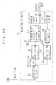
- Fig. 2b shows the structure of the sensing circuit 2 of the object sensor 1
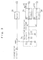
- Fig. 3 shows the structure of a detection circuit 2a of the sensing circuit 2.
- the sensing circuit 2 comprises the detection circuit 2a, an AC amplifying circuit 2b, a comparator circuit 2c, a DC amplifying circuit 2d, a comparator circuit 2e, and an OR gate 2f.
- the AC amplifying circuit 2b amplifies an AC component of a detection voltage.
- the comparator circuit 2c outputs a relative change signal that attains a high level H when the output of the AC amplifying circuit 2b deviates from a predetermined voltage range (predetermined voltage V1 to V2, which is higher than V1).
- the DC amplifying circuit 2d amplifies a DC component of the detection voltage.
- the comparator circuit 2e outputs an absolute change signal which attains a high level H when the output of the DC amplifying circuit 2d exceeds the predetermined voltage V2.
- the OR gate 2f outputs a sensor signal SEN that attains a high level H when either the relative change signal output from the comparator 2c or the absolute change signal output from the comparator 2e attains a high level H. Attainment of the high level H by the sensor signal SEN of the OR gate 2f indicates that an object such as a human hand 9 is in contact with or in proximity to the antenna 23.
- the oscillation circuit 26a shown in Fig. 2a oscillates at a constant frequency (in the present embodiment, at 2.45 GHz).
- the variable gain amplifier 26b is set to a low gain, and the modulator 26d is in an ON state, the oscillating signal is fed to the antenna 23 such that the impedance is adjusted to 50 ⁇ for matching with the antenna 23.
- the input impedance of the antenna 23 changes, with the result that the above-described matched state is cancelled and an unmatched state is created. Consequently, when the object 9 approaches to the antenna 23, the voltage standing wave in the feed line changes, so that the voltage in the feed line increases by a certain amount.
- a radio wave radiated from the antenna 23 reflects on the object 9 and is received by the antenna 23, so that interference arises in the feed line between the transmitted signal and the received signal. While the object 9 is moving, the degree of the interference changes in accordance with the speed of approach.
- An interference wave is detected by the detection circuit 2a, and an AC component of the detection voltage is amplified in order to produce a relative change signal that corresponds to the relative speed of the object 9 with respect to the antenna 23. Further, a DC component of the detection voltage is amplified in order to produce an absolute change signal that corresponds to a position of the object 9 in relation to the antenna 23.
- the AC component of the detection voltage represents a relative change that corresponds to a speed of approach of the object 9 to the antenna 23; i.e., variation in voltage due to the Doppler effect
- the DC component of the detection voltage represents the distance between the object 9 and the antenna 23. Sensing of the object 9 based on the AC component of the detection voltage becomes possible earlier than does sensing of the object 9 based on the DC component of the detection voltage.
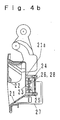
- An outside handle (hereinafter referred to as a "door handle”) 20 is provided on a driver-side door of the vehicle.
- the door handle 20 is formed of die cast zinc and its surface is coated with chromium plating.
- the door handle 20 is equipped with a key cylinder 27 and includes a base plate member 21 and a doorknob 22.
- a depression is formed on the outer side of the base plate member 21 in order to allow a driver to insert his/her hand into the door handle 20.
- the doorknob 22 can be turned relative to the base plate member 21 in a clockwise direction as viewed in Fig. 4b.
- a straight slit for the antenna 23 is cut in the bottom wall 21a of the base plate member 21.
- the slit is filled with a synthetic resin, such that the opening of the slit is closed by the synthetic resin.
- the slit assumes the form of a straight line; however, the shape of the slit is not limited thereto.
- Two seating bases 23 are provided on the bottom wall 21a, and threaded holes are formed in the seating bases 23. Screws 24 and 25 are screwed into the threaded holes, and an output-side terminal of the balun 28 is integrally connected to the screws 24 and 25.
- One end of a coaxial cable (feed line) is connected to the input-side terminal of the balun 28.
- the other end of the coaxial cable is connected to the transmission circuit 26.
- the slit provided in the door handle 20 serves as the antenna 23 that transmits a request signal to the portable unit 10. That is, the object sensor 1 functions as a transmitter for transmitting the request signal.
- the doorknob is not limited to a pull-up type door handle (a door handle that swings in the vertical direction) as shown in Fig. 4b, and may assume the form of a grip-type door handle (a door handle that swings in the widthwise direction of the vehicle).
- a signal received by an antenna 18 is detected and amplified by a receiver 17 serving as a detector and is then input to the controller 11.
- the output of an amplifier 17a of the receiver 17 attains a high level H when a reception signal is detected, and attains a low level L when no reception signal is detected.
- a lock switch 14 and an unlock switch 13 are normal-open switches. When a driver depresses the lock switch 14 or the unlock switch 13, the lock switch 14 or the unlock switch 13 supplies to the controller 11 a high level signal from a DC power supply 12.
- the controller 11 When the controller 11 receives a high-level trigger signal from the amplifier 17a, the lock switch 14, or the unlock switch 13, the controller 11 serially reads out an ID code stored in an internal register and serially outputs the ID code to the transmitter 15 while adding bits K 0 -K 2 thereto.
- the controller 11 sets bit K 0 to 1 (H) when a high level trigger is output from the amplifier 17a, sets bit K 2 to 1 when a high level trigger is output from the lock switch 14, and sets bit K 1 to 1 when a high level trigger is output from the unlock switch 13.
- the ID code is data that identifies the portable unit 10, and the same ID code is stored in the controller 31 of the control apparatus 30.
- the output of the controller 11 is supplied to a resonator element 15a and a variable capacitance diode 15b, and is applied to the base of a transistor 15c via the resonator element 15a. Therefore, the capacitance of the variable capacitance diode 15b changes depending on whether each bit of the ID code assumes the value 1 (H) or 0 (L).
- the emitter of the transistor 15c is grounded via a capacitor 15e and a resistor 15f.
- the collector of the transistor 15c is connected to one end of a communications antenna 16.
- a capacitor 15d is connected between the base and the emitter of the transistor 15c.
- the transistor 15c is in an ON state regardless of whether each bit of the ID code is 1 (H) or 0 (L).
- the load capacitance of the resonator element 15a changes depending on the level of each bit of the ID code, and the oscillation frequency of the transmitter 15 changes in accordance with the change in the load capacitance.
- a wave that has been frequency-modulated in accordance with the ID code is transmitted from the antenna 16.
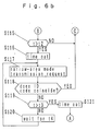
- Figs. 6a and 6b show the details of an "entry processing" ENP1 performed by the controller 31 of the control apparatus 30.
- the entry processing ENP1 is performed when the driver-side door is locked while the vehicle is in a parked state.
- the controller 31 enters a human sensor mode or an object-approach monitor mode, in which the controller 31 waits, while measuring a wait time t, until the output signal SEN of the sensing circuit 2 becomes H to indicate detection of, for example, a hand present in front of the slit 23 of the door handle (S103 and S104).
- step S105 the controller 31 brings to an L level the unlock signal line of the door lock control switch 43. That is, the controller 31 unlocks the door.
- step S106 the controller 31 starts timers which measure passage of time td and passage of time ts, and waits until the door is opened (step S107).
- the entry processing ENP1 is ended, and the controller 31 returns to an unillustrated main routine.
- the controller 31 waits until the door is closed (until the driver enters the vehicle and closes the door).
- the controller 31 further waits until the ignition switch 51 is opened (the engine is stopped), the door is opened (the driver exits the vehicle), and the door is then closed (the door is closed by the driver who has exited the vehicle).
- the controller 31 starts an "exit processing" for closing the window and locking the door.
- the controller 31 closes the window, and outputs a low-power transmission command to the transmission circuit 26 at predetermined intervals to thereby transmit request data (transmission request signal).
- request data transmission request signal
- the controller 31 repeats the transmission of the low-power transmission command, and locks the door when the transmission is performed a predetermined number of times after receipt of the response becomes impossible. Subsequently, the controller 31 returns to the main routine. Since the vehicle is in a parked state and the door is in a locked state, the controller 31 starts the entry processing ENP1.
- the controller 31 waits until the door is opened. However, when the clocked time ts exceeds t6, the controller 31 starts a drive for opening the window, and continues the drive for opening the window until the window is fully opened (steps S111-S114). This operation enables the window to be opened when the driver touches the door handle for the predetermined period t6 after detection of coincidence between the received ID code and the stored ID code. Thus, a special switch or the like becomes unnecessary.
- the controller 31 checks (in step S115) whether the output signal SEN of the sensing circuit 2 is H (whether a hand is sensed). When no hand is detected within the period t2, the controller 31 outputs a low-power transmission command to the transmission circuit 26 in order to transmit request data (transmission request signal). Subsequently, the controller 31 waits until the receiver 33 receives a reply signal. Upon receipt of the reply signal, the controller 31 checks whether an ID code represented by the received reply signal coincides with the ID code stored in the controller 31.
- the controller 31 transmits request data again after awaiting passage of time t4 (100 msec) (steps S117 - S120).
- t4 100 msec
- the controller 31 returns to step S100.
- Fig. 8 shows an area within which the above-described request data (transmission request signal) are transmitted.
- request data request data
- the portable unit 10 can receive the request data (transmission request signal) if the portable unit 10 is located within a wider area Ai.
- the portable unit 10 can receive the request data only when the portable unit 10 is located within a narrower area As.
- Transmission in a wide area mode or transmission of the high-power transmission command is performed at intervals t1 (600 msec).
- Transmission in a narrow area mode or transmission of the low-power transmission command is performed at intervals t4 (100 msec). Therefore, the interval t4 is one-sixth of the interval t1.
- Fig. 7a and 7b shows the details of "entry processing" ENP2 performed by the controller 31 according to another embodiment of the present invention.
- the controller 31 after locking the door in step S110, the controller 31 proceeds to a narrow area mode in step S117.
- the controller proceeds to step S117 and transmits a low-power transmission command.
- consumed power is decreased as in the above-described case.
- a remote control apparatus comprises a vehicle-mounted unit including a transmitter (26, 28, 23) for transmitting an ID request, a receiver (32, 33) for receiving a reply ID transmitted in response to the ID request, controller (31) for controlling the operation state of equipment (40, 60) depending on whether the receiver (32, 33) receives the ID, as well as a portable unit (10) for transmitting a reply ID in response to the ID request.
- controller (31) for controlling the operation state of equipment (40, 60) depending on whether the receiver (32, 33) receives the ID, as well as a portable unit (10) for transmitting a reply ID in response to the ID request.
- the controller (31) decreases the transmission power of the ID request.
- the hand sensor (1) comprises a slot antenna having an outside door handle, the surface of which is formed of a conductive material, a slit formed in the conductive material, and feeding points. The antenna is used for transmission of the ID request.
Landscapes
- Engineering & Computer Science (AREA)
- Mechanical Engineering (AREA)
- Computer Networks & Wireless Communication (AREA)
- Physics & Mathematics (AREA)
- General Physics & Mathematics (AREA)
- Lock And Its Accessories (AREA)
- Radar Systems Or Details Thereof (AREA)
Claims (10)
- Fernbedienungsvorrichtung für ein Fahrzeug, mit:einem Sender (26, 28, 23) zum Senden eines Sendeaufforderungssignals an eine tragbare Einheit (10);einem Empfänger (32, 33) zum Empfangen eines Antwortsignals, das durch die tragbare Einheit (10) als Antwort auf das Sendeaufforderungssignal gesendet wird, und einen ID-Code umfasst;einem Objektsensor (1), der in der Umgebung einer Fahrzeugausstattung (40, 60) angeordnet ist, zum Erfassen der Anwesenheit eines Menschen;einer Betriebssteuerungseinrichtung (31) zum Steuern des Betriebszustandes der Ausstattung (40, 60) abhängig davon, ob der durch den Empfänger (32, 33) empfangene ID-Code mit einem in dem Empfänger gespeicherten Code übereinstimmt, und wenn der Objektsensor (1) einen Menschen erkennt; undeiner Sendeleistungssteuerungseinrichtung (31) zum Reduzieren der Sendeleistung des Sendeaufforderungssignals von dem Sender (26, 28, 23), wenn der Objektsensor (1) kein Objekt erkennt, und der Empfänger (32, 33) eine ID-Code-Übereinstimmung erfasst.
- Fernbedienungsvorrichtung gemäß Anspruch 1, wobei die Sendeleistungssteuerungseinrichtung (31) den Sender (26, 28, 23) veranlasst, ein Sendeaufforderungssignal in einem vorbestimmten Intervall t1 zu senden, wenn der Empfänger (32, 33) kein Antwortsignal empfängt, und das Senden des Sendeaufforderungssignals unterdrückt, wenn der Empfänger (32, 33) ein Antwortsignal empfängt.
- Fernbedienungsvorrichtung gemäß Anspruch 2, wobei das Unterdrücken des Sendens des Sendeaufforderungssignals ein Beenden des Sendens des Sendeaufforderungssignals ist.
- Fernbedienungsvorrichtung gemäß Anspruch 3, wobei die Sendeleistungssteuerungseinrichtung (31) nach Beenden des Sendens des Sendeaufforderungssignals anschließend eine vorbestimmte Periode t2 abwartet, bis der Objektsensor (1) ein Objekt erfasst, und den Sender (26, 28, 23) ein zweites Mal veranlasst, das Sendeaufforderungssignal zu senden, wenn die vorbestimmte Periode t2 abgelaufen ist, während der der Objektsensor (1) kein Objekt erkennt.
- Fernbedienungsvorrichtung gemäß Anspruch 3, wobei eine Leistung des Sendens des Sendeaufforderungssignals des zweiten Mals geringer als die des Sendens des Sendeaufforderungssignals des vorbestimmten Intervalls t1 ist.
- Fernbedienungsvorrichtung gemäß Anspruch 1, wobei die Ausstattung einen Tür-Verriegelungs-/Entriegelungsmechanismus (40) umfasst und die Betriebssteuerungseinrichtung (31) den Tür-Verriegelungs-/Entriegelungsmechanismus (40) für eine Entriegelungsbetrieb ansteuert, wenn ein durch den Empfänger (32, 33) empfangenes Antwortsignal einen vorbestimmten Identifizierungscode darstellt und der Objektsensor (1) ein Objekt erfasst.
- Fernbedienungsvorrichtung gemäß Anspruch 3, wobei die Fernbedienungsvorrichtung weiterhin einen Offen-/Geschlossen-Sensor (52) zum Erzeugen eines Signals umfasst, das einen Offen-/Geschlossen-Zustand der Türe angibt; die Ausstattung einen Türfensterantriebsmechanismus (60) umfasst; und die Betriebssteuerungseinrichtung (31) dem Türfensterantriebsmechanismus (60) veranlasst, ein Türfenster zu öffnen, wenn der Objektsensor (1), nachdem der Tür-Verriegelungs-/Entriegelungsmechanismus (40) für einen Entriegelungsbetrieb angesteuert wird, fortwährend ein Objekt erfasst und der Offen-/Geschlossen-Sensor (52) fortwährend ein Tür-Geschlossen-Signal für eine vorbestimmte Periode t6 ausgibt.
- Fernbedienungsvorrichtung gemäß Anspruch 3, wobei die Betriebssteuerungseinrichtung (31) den Tür-Verriegelungs-/Entriegelungsmechanismus (40) für einen Verriegelungsbetrieb ansteuert, nachdem der Tür-Verriegelungs-/Entriegelungsmechanismus (40) für einen Entriegelungsbetrieb angesteuert wird, der Objektsensor (1) kein Objekt erfasst, und der Offen-/Geschlossen-Sensor (52) fortwährend ein Tür-Geschlossen-Signal für eine vorbestimmte Periode t5 ausgibt.
- Fernbedienungsvorrichtung gemäß Anspruch 1, wobei der Objektsensor (1) eine Schlitzantenne (21, 23-25) aufweist, die einen Außentürgriff (20), wobei mindestens die Oberfläche von diesem aus einem leitfähigen Material ausgebildet ist, einen in dem leitfähigen Material ausgebildeten Schlitz (23) und auf dem leitfähigen Material bereitgestellte Einspeisungspunkte (24, 25) aufweist; und der Sender (26, 28, 23) die Einspeisungspunkte (24, 25) mit einer Funkwellensendespannung versorgt.
- Fernbedienungsvorrichtung gemäß Anspruch 1, wobei der Sender (26) eine Umschalteinrichtung (26c) zum Ändern der Sendeausgabe zwischen einer leistungsstarken Ausgabe und einer leistungsschwachen Ausgabe umfasst.
Applications Claiming Priority (2)
| Application Number | Priority Date | Filing Date | Title |
|---|---|---|---|
| JP19042998A JP3591761B2 (ja) | 1998-07-06 | 1998-07-06 | 遠隔制御装置 |
| JP19042998 | 1998-07-06 |
Publications (3)
| Publication Number | Publication Date |
|---|---|
| EP0970859A2 EP0970859A2 (de) | 2000-01-12 |
| EP0970859A3 EP0970859A3 (de) | 2003-02-12 |
| EP0970859B1 true EP0970859B1 (de) | 2007-02-14 |
Family
ID=16257991
Family Applications (1)
| Application Number | Title | Priority Date | Filing Date |
|---|---|---|---|
| EP19990112945 Expired - Lifetime EP0970859B1 (de) | 1998-07-06 | 1999-07-05 | Fernbedienung |
Country Status (4)
| Country | Link |
|---|---|
| US (1) | US6281599B1 (de) |
| EP (1) | EP0970859B1 (de) |
| JP (1) | JP3591761B2 (de) |
| DE (1) | DE69935091T2 (de) |
Families Citing this family (37)
| Publication number | Priority date | Publication date | Assignee | Title |
|---|---|---|---|---|
| JP3673099B2 (ja) * | 1998-12-03 | 2005-07-20 | 株式会社東海理化電機製作所 | 車両用ドアロック制御システム |
| FR2813630B1 (fr) | 2000-09-05 | 2003-08-01 | Valeo Electronique | Procede pour verrouiller automatiquement un ouvrant de vehicule a l'aide d'un systeme d'acces mains libres et d'un capteur d'approche |
| FR2827064B1 (fr) * | 2001-07-04 | 2004-04-16 | Valeo Electronique | Procede de traitement de signaux de detection provenant d'au moins une zone de detection d'un vehicule automobile, dispositif pour mettre en oeuvre ce procede et poignee de vehicule automobile |
| DE60142440D1 (de) * | 2000-09-05 | 2010-08-05 | Valeo Securite Habitacle Sas | Verfahren zur detektionssignalverarbeitung für ein kraftfahrzeug |
| GB0110976D0 (en) * | 2001-05-04 | 2001-06-27 | Meritor Light Vehicle Sys Ltd | Scanning device |
| JP4402338B2 (ja) * | 2002-08-29 | 2010-01-20 | 株式会社東海理化電機製作所 | 電子キーシステム |
| JP2006518817A (ja) * | 2003-02-25 | 2006-08-17 | オーストラリアン アロー ピーティーワイ リミテッド | アクセス制御 |
| WO2005038483A1 (ja) | 2003-10-17 | 2005-04-28 | Aisin Seiki Kabushiki Kaisha | 近接センサ |
| US20050195106A1 (en) * | 2004-03-03 | 2005-09-08 | Davis Alan C. | Hand held wireless occupant communicator |
| US20070146209A1 (en) * | 2004-03-30 | 2007-06-28 | Aisin Seiki Kabushiki Kaisha | Condition detecting sensor |
| JP2006028956A (ja) * | 2004-07-20 | 2006-02-02 | Alps Electric Co Ltd | パッシブキーレスエントリー装置 |
| JP4679933B2 (ja) * | 2005-03-02 | 2011-05-11 | アルプス電気株式会社 | キーレスエントリー装置 |
| US20060220785A1 (en) * | 2005-03-31 | 2006-10-05 | Torbjoern Ferdman | Generic radio transmission network for door applications |
| US20090160608A1 (en) * | 2005-04-22 | 2009-06-25 | Matsushita Electric Industrial Co., Ltd. | Motorcar |
| US7518326B2 (en) | 2006-01-20 | 2009-04-14 | Albany International Corp. | Wireless communication system for a roll-up door |
| FR2900181B1 (fr) * | 2006-04-25 | 2008-06-13 | Siemens Vdo Automotive Sas | Dispositif de condamnation/decondamnation mains libres des ouvrants d'un vehicule |
| JP4662211B2 (ja) | 2006-09-12 | 2011-03-30 | 株式会社デンソー | 車載用無線送信装置 |
| FR2927927A1 (fr) * | 2008-02-26 | 2009-08-28 | Peugeot Citroen Automobiles Sa | Dispositif et procede de controle d'acces main libre a un vehicule automobile, a contole de descente de vitre(s) |
| US7916021B2 (en) * | 2008-08-13 | 2011-03-29 | Honda Motor Co., Ltd. | Smart entry system and method |
| JP5169759B2 (ja) * | 2008-11-14 | 2013-03-27 | 三菱自動車工業株式会社 | 触手検出装置および車両制御システム |
| TWI381961B (zh) * | 2008-11-26 | 2013-01-11 | Htc Corp | 具有車用電腦之車輛以及啟動車用電腦的方法 |
| EP2494132A1 (de) * | 2009-10-28 | 2012-09-05 | UTC Fire & Security Corporation | Drahtlosfähige antenne für eine sicherheitstür |
| US8482376B2 (en) | 2009-11-02 | 2013-07-09 | Rockwell Automation Technologies, Inc. | Reteachable switching circuit with ability for locking |
| DE102010004490A1 (de) * | 2010-01-12 | 2011-07-14 | Bircher Reglomat Ag | Steuerungssystem für einen Türflügel |
| CN202217782U (zh) * | 2010-05-24 | 2012-05-09 | Tdk株式会社 | 接近型天线以及无线通信设备 |
| FR2978784B1 (fr) * | 2011-08-05 | 2013-09-06 | Continental Automotive France | Procede et dispositif de declenchement, au moyen d'un lecteur rfid, d'une procedure d'actionnement de moyens de condamnation/de-condamnation de portes d'acces d'un vehicule automobile |
| US9335922B2 (en) * | 2013-01-16 | 2016-05-10 | Research In Motion Limited | Electronic device including three-dimensional gesture detecting display |
| US9323380B2 (en) | 2013-01-16 | 2016-04-26 | Blackberry Limited | Electronic device with touch-sensitive display and three-dimensional gesture-detection |
| JP6111169B2 (ja) * | 2013-08-26 | 2017-04-05 | 本田技研工業株式会社 | スマートエントリシステム |
| US9865111B2 (en) | 2015-03-30 | 2018-01-09 | Ford Global Technologies, Llc | Fob case for reduced transmission interference |
| US9380540B1 (en) | 2015-03-30 | 2016-06-28 | Ford Global Technologies, Llc | Key fob transmission compensation |
| US9807704B2 (en) | 2015-03-30 | 2017-10-31 | Ford Global Technologies, Llc | Key fob transmission compensation |
| JP6499060B2 (ja) * | 2015-11-13 | 2019-04-10 | 株式会社ホンダロック | 車両用アウトハンドル装置 |
| JP6855951B2 (ja) | 2017-06-15 | 2021-04-07 | トヨタ自動車株式会社 | 車両用制御装置 |
| CN110088643B (zh) * | 2018-08-31 | 2021-12-07 | 深圳迈睿智能科技有限公司 | 人体存在探测器及其人体存在探测方法 |
| US12180746B2 (en) * | 2021-05-17 | 2024-12-31 | Knoll, Inc. | Storage apparatus |
| CN116612563B (zh) * | 2023-05-29 | 2025-10-24 | 长城汽车股份有限公司 | 车辆与钥匙的通信方法、电子设备及车辆 |
Family Cites Families (13)
| Publication number | Priority date | Publication date | Assignee | Title |
|---|---|---|---|---|
| US4897643A (en) * | 1986-08-11 | 1990-01-30 | Mazda Motor Corporation | Vehicular electronic equipment with door lock and side window antenna |
| IT1201858B (it) * | 1986-12-03 | 1989-02-02 | Delta Elettronica Spa | Impianto antifurto |
| DE69202281T2 (de) | 1991-03-06 | 1995-09-07 | Delco Electronics Corp | Fernbetätigungssystem zum Regeln einer Funktion einer Basisstation. |
| US5252965A (en) | 1991-03-15 | 1993-10-12 | Delco Electronics Corporation | Changing one of many access codes upon removal of ignition key |
| JPH05106376A (ja) | 1991-10-17 | 1993-04-27 | Nissan Motor Co Ltd | キーレスエントリーシステム |
| US5276728A (en) * | 1991-11-06 | 1994-01-04 | Kenneth Pagliaroli | Remotely activated automobile disabling system |
| JP3192715B2 (ja) | 1991-12-04 | 2001-07-30 | 富士通テン株式会社 | 車両用ワイヤレスドアロック制御装置 |
| JPH07150835A (ja) | 1993-11-29 | 1995-06-13 | Alpha Corp | 運転管理システム |
| IS4292A (is) * | 1994-07-12 | 1996-01-13 | Mul-T-Lock Technologies Ltd. | Rafeindathjófavörn fyrir farartæki |
| US5541585A (en) * | 1994-10-11 | 1996-07-30 | Stanley Home Automation | Security system for controlling building access |
| US5973611A (en) * | 1995-03-27 | 1999-10-26 | Ut Automotive Dearborn, Inc. | Hands-free remote entry system |
| DE19516316C2 (de) * | 1995-05-04 | 1998-11-26 | Kiekert Ag | Sicherheitseinrichtung an einem Kraftfahrzeug, welche lediglich einer zum Öffnen des Kraftfahrzeuges berechtigten Person das Öffnen des Kraftfahrzeuges erlaubt |
| DE19652227A1 (de) * | 1996-12-16 | 1998-06-18 | Bosch Gmbh Robert | Verfahren und Vorrichtung zum Zuordnen einer Fernbedienung zu einer Basisstation |
-
1998
- 1998-07-06 JP JP19042998A patent/JP3591761B2/ja not_active Expired - Fee Related
-
1999
- 1999-07-01 US US09/345,838 patent/US6281599B1/en not_active Expired - Lifetime
- 1999-07-05 DE DE1999635091 patent/DE69935091T2/de not_active Expired - Lifetime
- 1999-07-05 EP EP19990112945 patent/EP0970859B1/de not_active Expired - Lifetime
Also Published As
| Publication number | Publication date |
|---|---|
| DE69935091D1 (de) | 2007-03-29 |
| JP3591761B2 (ja) | 2004-11-24 |
| EP0970859A3 (de) | 2003-02-12 |
| DE69935091T2 (de) | 2007-11-15 |
| JP2000017916A (ja) | 2000-01-18 |
| US6281599B1 (en) | 2001-08-28 |
| EP0970859A2 (de) | 2000-01-12 |
Similar Documents
| Publication | Publication Date | Title |
|---|---|---|
| EP0970859B1 (de) | Fernbedienung | |
| US6304168B1 (en) | Door approach communication apparatus and door lock control apparatus | |
| US7181189B2 (en) | Vehicular remote control system and tire pressure monitoring system | |
| US6958675B2 (en) | Vehicle remote controller | |
| EP1134134B1 (de) | Sicherheitssystem zum Ermöglichen eines authentifizierten Zugangs einer Person zu einem gesichertem Raum | |
| US7283034B2 (en) | Object sensor and controller | |
| US7305284B2 (en) | Remote control system and method for vehicle | |
| US6476517B1 (en) | Vehicle automatic door-locking system using identifier signal transmitting portable unit | |
| US7071812B2 (en) | Detector and lock controller using same | |
| US20010038328A1 (en) | Multifunction and multiple range RKE system and method | |
| US20060012462A1 (en) | Remote control system | |
| US20040257296A1 (en) | Door handle for a vehicle | |
| US10160420B2 (en) | Vehicle control apparatus | |
| US9126564B2 (en) | Communication apparatus for vehicle | |
| US6882268B2 (en) | Method for keyless unlocking of an access door to a closed space | |
| EP0903456A1 (de) | Empfänger zum Gebrauch in einem schlüssellosen Eingangssystem für Kraftfahrzeuge | |
| JP2010031456A (ja) | 電子キーシステム | |
| US7167780B2 (en) | Remote control communication system and transmitting and receiving apparatuses | |
| JPH11182109A (ja) | 物体検知センサおよびそれを用いたドアロック制御装置 | |
| JP3669883B2 (ja) | 車両キーレスエントリー装置 | |
| JP3541684B2 (ja) | 遠隔制御装置 | |
| JP3436131B2 (ja) | 車載機器遠隔制御装置 | |
| JP5590482B2 (ja) | スイッチングシステム | |
| JP2002004663A (ja) | 自動車のドアロック制御システム | |
| JPH10238184A (ja) | オートドアロック制御装置 |
Legal Events
| Date | Code | Title | Description |
|---|---|---|---|
| PUAI | Public reference made under article 153(3) epc to a published international application that has entered the european phase |
Free format text: ORIGINAL CODE: 0009012 |
|
| AK | Designated contracting states |
Kind code of ref document: A2 Designated state(s): AT BE CH CY DE DK ES FI FR GB GR IE IT LI LU MC NL PT SE |
|
| AX | Request for extension of the european patent |
Free format text: AL;LT;LV;MK;RO;SI |
|
| PUAL | Search report despatched |
Free format text: ORIGINAL CODE: 0009013 |
|
| AK | Designated contracting states |
Designated state(s): AT BE CH CY DE DK ES FI FR GB GR IE IT LI LU MC NL PT SE |
|
| AX | Request for extension of the european patent |
Extension state: AL LT LV MK RO SI |
|
| RIC1 | Information provided on ipc code assigned before grant |
Ipc: 7G 07C 9/00 B Ipc: 7E 05B 49/00 B Ipc: 7B 60R 25/00 A |
|
| 17P | Request for examination filed |
Effective date: 20030409 |
|
| 17Q | First examination report despatched |
Effective date: 20030730 |
|
| AKX | Designation fees paid |
Designated state(s): DE FR GB |
|
| GRAP | Despatch of communication of intention to grant a patent |
Free format text: ORIGINAL CODE: EPIDOSNIGR1 |
|
| GRAS | Grant fee paid |
Free format text: ORIGINAL CODE: EPIDOSNIGR3 |
|
| GRAA | (expected) grant |
Free format text: ORIGINAL CODE: 0009210 |
|
| RAP1 | Party data changed (applicant data changed or rights of an application transferred) |
Owner name: TOYOTA JIDOSHA KABUSHIKI KAISHA Owner name: AISIN SEIKI KABUSHIKI KAISHA |
|
| AK | Designated contracting states |
Kind code of ref document: B1 Designated state(s): DE FR GB |
|
| REG | Reference to a national code |
Ref country code: GB Ref legal event code: FG4D |
|
| REF | Corresponds to: |
Ref document number: 69935091 Country of ref document: DE Date of ref document: 20070329 Kind code of ref document: P |
|
| ET | Fr: translation filed | ||
| PLBE | No opposition filed within time limit |
Free format text: ORIGINAL CODE: 0009261 |
|
| STAA | Information on the status of an ep patent application or granted ep patent |
Free format text: STATUS: NO OPPOSITION FILED WITHIN TIME LIMIT |
|
| 26N | No opposition filed |
Effective date: 20071115 |
|
| REG | Reference to a national code |
Ref country code: DE Ref legal event code: R084 Ref document number: 69935091 Country of ref document: DE |
|
| REG | Reference to a national code |
Ref country code: DE Ref legal event code: R084 Ref document number: 69935091 Country of ref document: DE Effective date: 20110713 |
|
| REG | Reference to a national code |
Ref country code: GB Ref legal event code: 746 Effective date: 20111114 |
|
| PGFP | Annual fee paid to national office [announced via postgrant information from national office to epo] |
Ref country code: DE Payment date: 20130703 Year of fee payment: 15 |
|
| PGFP | Annual fee paid to national office [announced via postgrant information from national office to epo] |
Ref country code: FR Payment date: 20130724 Year of fee payment: 15 Ref country code: GB Payment date: 20130703 Year of fee payment: 15 |
|
| REG | Reference to a national code |
Ref country code: DE Ref legal event code: R119 Ref document number: 69935091 Country of ref document: DE |
|
| GBPC | Gb: european patent ceased through non-payment of renewal fee |
Effective date: 20140705 |
|
| REG | Reference to a national code |
Ref country code: FR Ref legal event code: ST Effective date: 20150331 |
|
| PG25 | Lapsed in a contracting state [announced via postgrant information from national office to epo] |
Ref country code: DE Free format text: LAPSE BECAUSE OF NON-PAYMENT OF DUE FEES Effective date: 20150203 |
|
| REG | Reference to a national code |
Ref country code: DE Ref legal event code: R119 Ref document number: 69935091 Country of ref document: DE Effective date: 20150203 |
|
| PG25 | Lapsed in a contracting state [announced via postgrant information from national office to epo] |
Ref country code: FR Free format text: LAPSE BECAUSE OF NON-PAYMENT OF DUE FEES Effective date: 20140731 Ref country code: GB Free format text: LAPSE BECAUSE OF NON-PAYMENT OF DUE FEES Effective date: 20140705 |