EP0970874A1 - Verfahren zum Vermindern der Drehmomentverteilung auf ein Hilfsventileiner hydraulischen Kraftfahrzeug-Servolenkung - Google Patents
Verfahren zum Vermindern der Drehmomentverteilung auf ein Hilfsventileiner hydraulischen Kraftfahrzeug-Servolenkung Download PDFInfo
- Publication number
- EP0970874A1 EP0970874A1 EP99420139A EP99420139A EP0970874A1 EP 0970874 A1 EP0970874 A1 EP 0970874A1 EP 99420139 A EP99420139 A EP 99420139A EP 99420139 A EP99420139 A EP 99420139A EP 0970874 A1 EP0970874 A1 EP 0970874A1
- Authority
- EP
- European Patent Office
- Prior art keywords
- torsion bar
- valve
- rotor
- assistance
- stiffness
- Prior art date
- Legal status (The legal status is an assumption and is not a legal conclusion. Google has not performed a legal analysis and makes no representation as to the accuracy of the status listed.)
- Granted
Links
- 238000000034 method Methods 0.000 title claims abstract description 23
- 239000006185 dispersion Substances 0.000 title claims description 12
- 230000006978 adaptation Effects 0.000 claims abstract description 16
- 238000005553 drilling Methods 0.000 claims description 6
- 238000005259 measurement Methods 0.000 claims description 4
- 238000009826 distribution Methods 0.000 claims description 3
- 239000007787 solid Substances 0.000 claims description 2
- 230000004913 activation Effects 0.000 claims 1
- 230000008878 coupling Effects 0.000 abstract 1
- 238000010168 coupling process Methods 0.000 abstract 1
- 238000005859 coupling reaction Methods 0.000 abstract 1
- 238000003754 machining Methods 0.000 description 4
- 239000012530 fluid Substances 0.000 description 3
- 238000009776 industrial production Methods 0.000 description 2
- 241001080024 Telles Species 0.000 description 1
- 238000004891 communication Methods 0.000 description 1
- 230000000295 complement effect Effects 0.000 description 1
- 238000011161 development Methods 0.000 description 1
- 238000012986 modification Methods 0.000 description 1
- 230000004048 modification Effects 0.000 description 1
- 230000007935 neutral effect Effects 0.000 description 1
Images
Classifications
-
- B—PERFORMING OPERATIONS; TRANSPORTING
- B62—LAND VEHICLES FOR TRAVELLING OTHERWISE THAN ON RAILS
- B62D—MOTOR VEHICLES; TRAILERS
- B62D5/00—Power-assisted or power-driven steering
- B62D5/06—Power-assisted or power-driven steering fluid, i.e. using a pressurised fluid for most or all the force required for steering a vehicle
- B62D5/08—Power-assisted or power-driven steering fluid, i.e. using a pressurised fluid for most or all the force required for steering a vehicle characterised by type of steering valve used
- B62D5/083—Rotary valves
-
- Y—GENERAL TAGGING OF NEW TECHNOLOGICAL DEVELOPMENTS; GENERAL TAGGING OF CROSS-SECTIONAL TECHNOLOGIES SPANNING OVER SEVERAL SECTIONS OF THE IPC; TECHNICAL SUBJECTS COVERED BY FORMER USPC CROSS-REFERENCE ART COLLECTIONS [XRACs] AND DIGESTS
- Y10—TECHNICAL SUBJECTS COVERED BY FORMER USPC
- Y10T—TECHNICAL SUBJECTS COVERED BY FORMER US CLASSIFICATION
- Y10T137/00—Fluid handling
- Y10T137/0318—Processes
- Y10T137/0402—Cleaning, repairing, or assembling
- Y10T137/0491—Valve or valve element assembling, disassembling, or replacing
-
- Y—GENERAL TAGGING OF NEW TECHNOLOGICAL DEVELOPMENTS; GENERAL TAGGING OF CROSS-SECTIONAL TECHNOLOGIES SPANNING OVER SEVERAL SECTIONS OF THE IPC; TECHNICAL SUBJECTS COVERED BY FORMER USPC CROSS-REFERENCE ART COLLECTIONS [XRACs] AND DIGESTS
- Y10—TECHNICAL SUBJECTS COVERED BY FORMER USPC
- Y10T—TECHNICAL SUBJECTS COVERED BY FORMER US CLASSIFICATION
- Y10T137/00—Fluid handling
- Y10T137/8593—Systems
- Y10T137/86493—Multi-way valve unit
- Y10T137/86574—Supply and exhaust
- Y10T137/86638—Rotary valve
- Y10T137/86646—Plug type
- Y10T137/86654—For plural lines
Definitions
- the present invention relates to assistance valves for hydraulic power steering of a motor vehicle. More in particular, this invention relates to a method which allows, as part of the industrial production of such assistance valves, reduce the dispersion of the "valve law" torque.
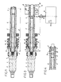
- Figure 1 of the accompanying schematic drawing shows, in section longitudinal, a traditional assistance valve (as known by example by French patent application N ° 2752809 or its equivalent European N ° 0827892 in the name of the Applicant), to recall the structure and operating principle, and to explain the problem to the basis of the present invention.
- a traditional assistance valve as known by example by French patent application N ° 2752809 or its equivalent European N ° 0827892 in the name of the Applicant
- the assistance valve comprises, arranged along its axis longitudinal 1, a pinion 2 which is intended to come permanently into taken with a rack (not shown) from the power steering.
- a torsion bar 3, arranged along the longitudinal axis 1, is linked to the pinion 2 by a rigid link 4, at one end of this torsion bar 3.
- a rotor 5 of generally tubular shape, mounted around the torsion bar 3, is centered by one of its ends in the pinion 2, via a bearing 6 which allows it an angular movement without constraint, but limited by a positive stop (not shown) provided between this rotor 5 and the pinion 2.
- the rotor 5 is centered, at its other end, on the bar of torsion 3, and it is rigidly linked to the latter, towards this end, by a connecting element, in particular a pin 7.
- a jacket 8, partially surrounding the rotor 5, is centered on this rotor 5 and angularly linked to the pinion 2 by another pin 9.
- Complementary hydraulic distribution grooves 10, 11 are fitted on the jacket 8, and in the area of the rotor 5 covered by the jacket 8, to allow the passage of hydraulic fluid to one either of the hydraulic power steering cylinder chambers. In operation, the relative angular positions of the grooves 10, 11 define variable flow sections for the hydraulic fluid.
- a resistant torque is exerted on the pinion 2 (coming from the grip of the vehicle wheels and transmitted through the rack), and on the rotor 5 an input torque from the flywheel direction of the vehicle.
- These two couples are in opposite directions, and they stress the torsion bar 3, causing an angular offset between the rotor 5 on the one hand, and the jacket 8 (angularly linked to the pinion 2) on the other hand.
- This angular offset opens, in proportion to the torque resulting, the hydraulic passage to a cylinder chamber, at the same time the opposite chamber is put in communication with the circuit hydraulic return.
- the pressure of the hydraulic fluid directed to one jack chambers called “assistance pressure" increases as as the angular offset grows, and is therefore a function increasing torque applied to the assistance valve.
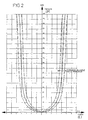
- this law is in particular determined by the characteristics of the torsion bar 3, which acts as a spring and makes it possible to adapt the necessary torque to angularly offset the rotor 5 relative to the jacket 8, in order to meet the specifications of car manufacturers.
- This characteristic of the torsion bar 3 is called angular stiffness; she depends on the geometry of said torsion bar, therefore on the definition of various diameters and lengths geometrically characterizing this bar.
- This distance is a predefined dimension D which depends, in particular, the axial position of the pin 7 on the rotor 5 and the bar torsion 3.
- the pin 7 has, for a type assistance valve given, only one axial position, therefore one position invariable.
- the necessary machining (simultaneous diametral drilling of the bar torsion 3 and rotor 5) to fit the pin 7 in its position predefined is performed, upon assembly of the assistance valve, after having carried out a hydraulic adjustment in order to obtain a valve law curve identical (symmetrical) for right turn and left turn.
- the present invention aims to avoid the disadvantage that constitutes such a dispersion of the assistance valve law, and its purpose is therefore to greatly reduce the dispersion of the torque, to obtain practically a same assistance pressure, on a large number of valves produced industrially.
- the invention relates to a method for the reduction of torque dispersion on an assistance valve for hydraulic power steering of a motor vehicle, the method consisting, for each assistance valve produced, of adjusting the stiffness the torsion bar and / or the connection between this torsion bar and the assistance valve rotor, depending on the difference between the law of valve or assistance law measured for this valve, and the theoretical law of type of assistance valve concerned.
- the inventive idea consists in adapting or modifying in especially the stiffness of the torsion bar, depending on the difference observed between the measured valve law and the theoretical one, in order to "refocus” at best the real valve law compared to the theoretical law desired.
- This solution reduces the dispersion of the valve law, on the whole of an industrial production more or less important.
- the stiffness of the torsion bar is adjusted by selecting the axial position of the connecting pin between this bar of torsion and the rotor of the assistance valve, so as to modify the free torsion distance of said torsion bar.
- a range of continuous adjustment of the axial position of said connecting pin is predefined, and for each assistance valve, this connecting pin is positioned axially, within the range of adjustment, in the calculated ideal position.
- the adaptation of the stiffness of the bar of torsion is carried out by the arrangement, on this torsion bar, one or more annular grooves, which locally decrease the section and thus induce a reduction in stiffness.
- each valve assistance is carried out using, for the connection between the bar torsion and the rotor, a connecting element which has its own stiffness editable.
- a connecting element which has its own stiffness editable.
- such an adaptation will be carried out using selectively a solid or hollow connecting pin, or by choosing the type of pin used here.
- a measure of the law valve or assistance law is made, for each valve assistance, before fitting the connecting pin between the bar torsion and the rotor, temporarily providing this connection by a tool outside the assistance valve, the result of this measurement being compared to the theoretical law to order a tool to adapt the stiffness the torsion bar and / or the connection between this torsion bar and the rotor.
- the tools temporarily providing the connection between the torsion bar and the rotor advantageously consists of a clamping assembly, comprising jaws acting on the outer end of the bar torsion, and on the corresponding end of the rotor.
- this can be made in the form a drilling and pin placement unit, movable in the axial direction of the assistance valve, to adapt the position axial of the connecting pin.
- this unit must also adapt the angular position of the pin, to arrange it in correspondence with the neutral point of the assistance valve.
- FIG. 3 an assistance valve is again shown, the structural elements corresponding to those previously described (with reference to FIG. 1) being designated by the same references digital, and not requiring a new description.
- a tool 12 outside the assistance valve intervenes to temporarily provide a rigid connection, between the outer end of the torsion bar 3 and the corresponding end of the rotor 5.
- the position axial of the connecting pin 7 can also be adjusted continuously, to within a predefined setting range, for example a range extending from extreme position A to other extreme position C.
- the adaptation of the overall stiffness of the bar of torsion 3 is effected by the arrangement of annular grooves 16 on this torsion bar 3, the grooves 16 locally reducing the cross-section of said bar 3.
- the grooves 16 are here hollowed out between the different predefined axial positions A, B and C of the connecting pin 7.
Landscapes
- Engineering & Computer Science (AREA)
- Chemical & Material Sciences (AREA)
- Combustion & Propulsion (AREA)
- Transportation (AREA)
- Mechanical Engineering (AREA)
- Power Steering Mechanism (AREA)
- Electrically Driven Valve-Operating Means (AREA)
Applications Claiming Priority (2)
| Application Number | Priority Date | Filing Date | Title |
|---|---|---|---|
| FR9808998 | 1998-07-09 | ||
| FR9808998A FR2780935B1 (fr) | 1998-07-09 | 1998-07-09 | Procede pour la reduction de la dispersion du couple sur une valve d'assistance pour direction assistee hydraulique de vehicule automobile |
Publications (2)
| Publication Number | Publication Date |
|---|---|
| EP0970874A1 true EP0970874A1 (de) | 2000-01-12 |
| EP0970874B1 EP0970874B1 (de) | 2003-04-09 |
Family
ID=9528606
Family Applications (1)
| Application Number | Title | Priority Date | Filing Date |
|---|---|---|---|
| EP99420139A Expired - Lifetime EP0970874B1 (de) | 1998-07-09 | 1999-06-18 | Verfahren zum Vermindern der Drehmomentverteilung auf ein Hilfsventileiner hydraulischen Kraftfahrzeug-Servolenkung |
Country Status (5)
| Country | Link |
|---|---|
| US (1) | US6216718B1 (de) |
| EP (1) | EP0970874B1 (de) |
| DE (1) | DE69906629T2 (de) |
| ES (1) | ES2193677T3 (de) |
| FR (1) | FR2780935B1 (de) |
Cited By (1)
| Publication number | Priority date | Publication date | Assignee | Title |
|---|---|---|---|---|
| CN110263413A (zh) * | 2019-06-14 | 2019-09-20 | 庆安集团有限公司 | 一种扭杆弹簧的优化设计方法 |
Families Citing this family (2)
| Publication number | Priority date | Publication date | Assignee | Title |
|---|---|---|---|---|
| FR2868382B1 (fr) * | 2004-04-05 | 2006-06-02 | Koyo Steering Europ K S E Soc | Procede pour l'ajustement d'une valve d'assistance de direction hydraulique de vehicule automobile |
| DE202005007092U1 (de) * | 2005-05-03 | 2005-08-11 | Trw Automotive Gmbh | Drehschieberventil, insbesondere für hydraulische Hilfskraftlenkungen bei Kraftfahrzeugen |
Citations (3)
| Publication number | Priority date | Publication date | Assignee | Title |
|---|---|---|---|---|
| EP0067572A2 (de) * | 1981-06-03 | 1982-12-22 | Trw Cam Gears Limited | Servolenkungseinrichtung |
| EP0396895A1 (de) * | 1989-05-12 | 1990-11-14 | Trw Inc. | Zahnstangen-Lenksystem |
| FR2752809A1 (fr) * | 1996-09-04 | 1998-03-06 | Soc D Mecanique D Irigny | Valve d'assistance pour direction assistee de vehicule automobile |
Family Cites Families (4)
| Publication number | Priority date | Publication date | Assignee | Title |
|---|---|---|---|---|
| JP2575905B2 (ja) * | 1989-12-05 | 1997-01-29 | ティーアールダブリュエスエスジェイ株式会社 | 動力操向装置のサーボバルブのセンタリング装置 |
| JPH0736868Y2 (ja) * | 1990-03-20 | 1995-08-23 | ティーアールダブリュエスアイ株式会社 | 動力操向装置におけるバルブアッシー構造 |
| WO1993009019A1 (en) * | 1991-10-29 | 1993-05-13 | Trw Steering & Suspension Australia Limited | Rotary valve for hydraulic power steering |
| DE4232813A1 (de) * | 1992-09-30 | 1994-03-31 | Zahnradfabrik Friedrichshafen | Zentriereinrichtung, insbesondere für Lenkventile |
-
1998
- 1998-07-09 FR FR9808998A patent/FR2780935B1/fr not_active Expired - Fee Related
-
1999
- 1999-06-18 ES ES99420139T patent/ES2193677T3/es not_active Expired - Lifetime
- 1999-06-18 DE DE69906629T patent/DE69906629T2/de not_active Expired - Lifetime
- 1999-06-18 EP EP99420139A patent/EP0970874B1/de not_active Expired - Lifetime
- 1999-07-06 US US09/347,639 patent/US6216718B1/en not_active Expired - Fee Related
Patent Citations (3)
| Publication number | Priority date | Publication date | Assignee | Title |
|---|---|---|---|---|
| EP0067572A2 (de) * | 1981-06-03 | 1982-12-22 | Trw Cam Gears Limited | Servolenkungseinrichtung |
| EP0396895A1 (de) * | 1989-05-12 | 1990-11-14 | Trw Inc. | Zahnstangen-Lenksystem |
| FR2752809A1 (fr) * | 1996-09-04 | 1998-03-06 | Soc D Mecanique D Irigny | Valve d'assistance pour direction assistee de vehicule automobile |
Cited By (1)
| Publication number | Priority date | Publication date | Assignee | Title |
|---|---|---|---|---|
| CN110263413A (zh) * | 2019-06-14 | 2019-09-20 | 庆安集团有限公司 | 一种扭杆弹簧的优化设计方法 |
Also Published As
| Publication number | Publication date |
|---|---|
| FR2780935B1 (fr) | 2000-09-15 |
| EP0970874B1 (de) | 2003-04-09 |
| DE69906629T2 (de) | 2004-02-05 |
| US6216718B1 (en) | 2001-04-17 |
| ES2193677T3 (es) | 2003-11-01 |
| DE69906629D1 (de) | 2003-05-15 |
| FR2780935A1 (fr) | 2000-01-14 |
Similar Documents
| Publication | Publication Date | Title |
|---|---|---|
| FR2543097A1 (fr) | Frein hydraulique a commande manuelle pour bicyclette et procede de freinage | |
| FR2733018A1 (fr) | Liaison solidaire en rotation | |
| EP0834676A1 (de) | Treibkette, insbesondere für Fahrrad | |
| FR2584658A1 (fr) | Suspension de roue arriere de vehicule a moteur | |
| EP0970874B1 (de) | Verfahren zum Vermindern der Drehmomentverteilung auf ein Hilfsventileiner hydraulischen Kraftfahrzeug-Servolenkung | |
| EP0091010B1 (de) | Kraftmessvorrichtung | |
| FR2530571A1 (fr) | Dispositif de cylindre et piston, engrenage de direction assistee utilisant ce dispositif et procede de fabrication d'un piston pour ce dispositif | |
| FR2620387A1 (fr) | Dispositif de support pour un stabilisateur fixe a la carrosserie d'un vehicule automobile | |
| EP0012043B1 (de) | Hydraulische Servolenkungseinrichtung für Kraftfahrzeuge | |
| FR2730774A1 (fr) | Joint homocinetique a rotule centrale | |
| FR2806951A1 (fr) | Dispositif de motorisation electrique pour pince d'outillage | |
| FR2699135A1 (fr) | Servocommande, en particulier servodirection pour véhicules automobiles. | |
| FR2798108A1 (fr) | Transmission a cremaillere ou direction a cremaillere | |
| FR2470658A1 (fr) | Appareil a cle oleodynamique de serrage servant a devisser et a serrer des ecrous | |
| FR2462609A1 (fr) | Accouplement cannele | |
| FR2727077A1 (fr) | Unite de commande d'une servosoupape | |
| FR2627827A1 (fr) | Joint de cardan a branches de fourches fendues | |
| FR2868382A1 (fr) | Procede pour l'ajustement d'une valve d'assistance de direction hydraulique de vehicule automobile | |
| FR2737176A1 (fr) | Direction assistee a cremaillere pour vehicules automobiles | |
| EP0976641B1 (de) | Zusammenbau einer Bedieneinheit mit einer Kraftfahrzeuglenksäule | |
| EP2316618A1 (de) | Werkzeug zur Messung des Spiels eines Gelenkes eines Kraftfahrzeugsrahmens und Verfahren dazu | |
| FR2688838A1 (fr) | Dispositif et procede pour relier coaxialement des parties de timoneries en plusieurs parties. | |
| FR2523803A1 (fr) | Charrue portee brabant | |
| FR2935664A1 (fr) | Systeme de direction en particulier pour vehicule automobile, comprenant un arbre de direction s'emboitant dans un percage d'un moyeu d'un volant | |
| FR3144807A1 (fr) | Ensemble de tringlerie pour diriger des roues d'un véhicule automobile |
Legal Events
| Date | Code | Title | Description |
|---|---|---|---|
| PUAI | Public reference made under article 153(3) epc to a published international application that has entered the european phase |
Free format text: ORIGINAL CODE: 0009012 |
|
| AK | Designated contracting states |
Kind code of ref document: A1 Designated state(s): DE ES GB IT SE |
|
| AX | Request for extension of the european patent |
Free format text: AL;LT;LV;MK;RO;SI |
|
| 17P | Request for examination filed |
Effective date: 20000327 |
|
| AKX | Designation fees paid |
Free format text: DE ES GB IT SE |
|
| GRAH | Despatch of communication of intention to grant a patent |
Free format text: ORIGINAL CODE: EPIDOS IGRA |
|
| GRAH | Despatch of communication of intention to grant a patent |
Free format text: ORIGINAL CODE: EPIDOS IGRA |
|
| GRAA | (expected) grant |
Free format text: ORIGINAL CODE: 0009210 |
|
| AK | Designated contracting states |
Designated state(s): DE ES GB IT SE |
|
| REG | Reference to a national code |
Ref country code: GB Ref legal event code: FG4D Free format text: NOT ENGLISH |
|
| PGFP | Annual fee paid to national office [announced via postgrant information from national office to epo] |
Ref country code: SE Payment date: 20030613 Year of fee payment: 5 Ref country code: GB Payment date: 20030613 Year of fee payment: 5 |
|
| PGFP | Annual fee paid to national office [announced via postgrant information from national office to epo] |
Ref country code: ES Payment date: 20030620 Year of fee payment: 5 |
|
| GBT | Gb: translation of ep patent filed (gb section 77(6)(a)/1977) | ||
| REG | Reference to a national code |
Ref country code: SE Ref legal event code: TRGR |
|
| REG | Reference to a national code |
Ref country code: ES Ref legal event code: FG2A Ref document number: 2193677 Country of ref document: ES Kind code of ref document: T3 |
|
| PLBE | No opposition filed within time limit |
Free format text: ORIGINAL CODE: 0009261 |
|
| STAA | Information on the status of an ep patent application or granted ep patent |
Free format text: STATUS: NO OPPOSITION FILED WITHIN TIME LIMIT |
|
| 26N | No opposition filed |
Effective date: 20040112 |
|
| PG25 | Lapsed in a contracting state [announced via postgrant information from national office to epo] |
Ref country code: GB Free format text: LAPSE BECAUSE OF NON-PAYMENT OF DUE FEES Effective date: 20040618 |
|
| PG25 | Lapsed in a contracting state [announced via postgrant information from national office to epo] |
Ref country code: SE Free format text: LAPSE BECAUSE OF NON-PAYMENT OF DUE FEES Effective date: 20040619 Ref country code: ES Free format text: LAPSE BECAUSE OF NON-PAYMENT OF DUE FEES Effective date: 20040619 |
|
| EUG | Se: european patent has lapsed | ||
| EUG | Se: european patent has lapsed | ||
| GBPC | Gb: european patent ceased through non-payment of renewal fee |
Effective date: 20040618 |
|
| PG25 | Lapsed in a contracting state [announced via postgrant information from national office to epo] |
Ref country code: IT Free format text: LAPSE BECAUSE OF NON-PAYMENT OF DUE FEES Effective date: 20050618 |
|
| REG | Reference to a national code |
Ref country code: ES Ref legal event code: FD2A Effective date: 20040619 |
|
| PGFP | Annual fee paid to national office [announced via postgrant information from national office to epo] |
Ref country code: DE Payment date: 20110415 Year of fee payment: 13 |
|
| REG | Reference to a national code |
Ref country code: DE Ref legal event code: R231 Ref document number: 69906629 Country of ref document: DE |
|
| PG25 | Lapsed in a contracting state [announced via postgrant information from national office to epo] |
Ref country code: DE Free format text: LAPSE BECAUSE OF THE APPLICANT RENOUNCES Effective date: 20120322 |