EP0970878A1 - Stopfen für eine Öffnung in einer Metallplatte - Google Patents
Stopfen für eine Öffnung in einer Metallplatte Download PDFInfo
- Publication number
- EP0970878A1 EP0970878A1 EP99401427A EP99401427A EP0970878A1 EP 0970878 A1 EP0970878 A1 EP 0970878A1 EP 99401427 A EP99401427 A EP 99401427A EP 99401427 A EP99401427 A EP 99401427A EP 0970878 A1 EP0970878 A1 EP 0970878A1
- Authority
- EP
- European Patent Office
- Prior art keywords
- obturator
- dome
- aperture
- annular part
- lip
- Prior art date
- Legal status (The legal status is an assumption and is not a legal conclusion. Google has not performed a legal analysis and makes no representation as to the accuracy of the status listed.)
- Withdrawn
Links
- 239000002184 metal Substances 0.000 title claims abstract description 16
- 230000002093 peripheral effect Effects 0.000 claims abstract description 23
- 239000000463 material Substances 0.000 claims description 5
- 239000004033 plastic Substances 0.000 claims description 4
- 229920003023 plastic Polymers 0.000 claims description 4
- 238000003780 insertion Methods 0.000 description 7
- 230000037431 insertion Effects 0.000 description 7
- QCDFBFJGMNKBDO-UHFFFAOYSA-N Clioquinol Chemical compound C1=CN=C2C(O)=C(I)C=C(Cl)C2=C1 QCDFBFJGMNKBDO-UHFFFAOYSA-N 0.000 description 1
- 229910000831 Steel Inorganic materials 0.000 description 1
- 238000010276 construction Methods 0.000 description 1
- 238000012986 modification Methods 0.000 description 1
- 230000004048 modification Effects 0.000 description 1
- 239000002991 molded plastic Substances 0.000 description 1
- 238000004080 punching Methods 0.000 description 1
- 230000003014 reinforcing effect Effects 0.000 description 1
- 238000007789 sealing Methods 0.000 description 1
- 239000010959 steel Substances 0.000 description 1
Images

Classifications
-
- B—PERFORMING OPERATIONS; TRANSPORTING
- B62—LAND VEHICLES FOR TRAVELLING OTHERWISE THAN ON RAILS
- B62D—MOTOR VEHICLES; TRAILERS
- B62D25/00—Superstructure or monocoque structure sub-units; Parts or details thereof not otherwise provided for
- B62D25/24—Superstructure sub-units with access or drainage openings having movable or removable closures; Sealing means therefor
-
- Y—GENERAL TAGGING OF NEW TECHNOLOGICAL DEVELOPMENTS; GENERAL TAGGING OF CROSS-SECTIONAL TECHNOLOGIES SPANNING OVER SEVERAL SECTIONS OF THE IPC; TECHNICAL SUBJECTS COVERED BY FORMER USPC CROSS-REFERENCE ART COLLECTIONS [XRACs] AND DIGESTS
- Y10—TECHNICAL SUBJECTS COVERED BY FORMER USPC
- Y10S—TECHNICAL SUBJECTS COVERED BY FORMER USPC CROSS-REFERENCE ART COLLECTIONS [XRACs] AND DIGESTS
- Y10S220/00—Receptacles
- Y10S220/19—Rubber plugs and caps
Definitions
- the present invention relates to an obturator for an aperture produced in a metal sheet, and in particular in a motor vehicle bodyshell.
- Such obturators are used to tightly close apertures generally produced in steel structures, such as those frequently encountered in motor vehicle construction.
- obturators are made from moulded plastics material and have a peripheral rim adapted to come into tight abutment against the periphery of the aperture to be obturated. They are fixed thanks to locking lugs which deform in the aperture upon the introduction of the obturator and which again assume, by elastic return movement, a spaced position in which these locking lugs extend beyond the contour of the aperture. Thus, the obturator is kept fixed in the aperture thanks to the peripheral rim and to the locking lugs situated on either side of the metal sheet in which the aperture is produced.
- the object of the present invention is to propose an obturator having a simplified and reliable assembly in apertures produced in metal sheets.
- the obturator specified by the invention comprises a central dome, a peripheral lip and an annular part extending between said dome and the lip, said annular part comprising a shoulder, and said dome being adapted to deform between a starting position and a position of locking of the obturator, in which the dome is turned inside out in relation to the said starting position, said annular part being adapted to expand between said starting position and said locking position and to be kept expanded by said dome turned inside out in the said locking position, the lip being adapted to come into abutment against a face of the aperture and the shoulder being adapted to be in abutment against an opposite face of the aperture in the said locking position.
- the turning inside out of the dome enables the annular part to be placed under tension against the contour of the aperture and the shoulder to be kept beneath the periphery of the aperture.
- the locking of the obturator in accordance with the invention is reliably achieved by the expansion of the annular part which bears the shoulder.
- the turning inside out of the dome in the aperture of the metal structure enables a sound resonance to be caused, which informs the operator in a simple manner of the achievement of the correct locking of the obturator in the aperture.
- the annular part and the dome form a groove in the starting position.
- the presence of the groove enables the obturator to be introduced into the aperture without any effort, the groove being able to easily absorb the relative tilting of the annular part and the dome upon the insertion of the obturator.
- the tilting of the annular part also enables the stability of the locking position to be reinforced. In fact, the tension exerted by the dome turned inside out on the annular part counteracts the tilting in the opposite direction of the annular part towards its inclined starting position, which would allow the obturator to come out of the aperture again.
- the contour of the shoulder and the end of the lip are coplanar when the obturator is in its starting position.
- the annular part is substantially transverse to the peripheral lip so that the latter remains in abutment against the periphery of the aperture upon the tilting of the annular part and tilts more or less as a function of the thickness of the structure in which the aperture is made.
- Such an obturator may thus be mounted tightly on metal sheets of different thicknesses and also absorb the local differences in thickness around the aperture in the presence of burrs, especially when the apertures are made by punching on the reverse of the metal sheet.
- the shoulder is formed by a series of teeth delimited by slots.
- the slots preferably extend over the annular part as far as the dome so that this annular part is sufficiently elastic to expand during the turning inside out of the dome.
- the teeth are regularly distributed over the annular part.
- the central portion of the dome has a thicker part made of plastics material and a face domed towards the outside of the dome in the starting position and towards the inside of the dome turned inside out in the locking position.
- This arrangement facilitates the deformation of the dome and contributes towards keeping the walls of the dome spaced with respect to tension in the locking position so as to reinforce the tensile force exerted on the annular part.
- This obturator is particularly well adapted for obturating apertures which are circular in shape, as it is itself preferably circular in shape.
- the obturator also has a plug fixed to the central dome and adapted, in the locking position of the obturator, to close off a cavity formed by the dome turned inside out and the annular part.
- This plug allows the propagation of vibrations and of the noise at the level of the aperture in the metal sheet to be limited and thus brings about a sound-dampening function for the obturator.
- the plug comprises a portion forming a cap and a peripheral rim which is deformable and adapted to come up against said peripheral lip in the locking position of the obturator.
- the portion forming a cap and the peripheral lip are substantially coplanar in the locking position of the obturator, so that the plug does not virtually form any excess thickness on the obturator.
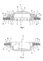
- the obturator comprises a central dome 1 and a peripheral lip 2. As better illustrated on Figures 3 and 4, an annular part 3 extends between the dome 1 and the lip 2.
- a shoulder is formed by a series of teeth 4 delimited by slots 5. These teeth 4 are distributed regularly over a lower face 3a of the annular part 3. As a non-restrictive example, the number of teeth 4 is equal to 16.
- the slots 5 extend over the annular part 3 as far as the dome 1, and thus extend to a connection portion 6 between the annular part 3 and the dome 1 of the obturator. In this example, the slots 5 also extend to the lip 2.
- annular part 3 is transverse to the peripheral lip 2.
- This annular part 3 and the peripheral lip 2 thus form around the dome 1 a bent-back skirt having a cross section in the shape of an open V.
- this obturator has a circular shape so that the lip 2 and the annular part 3 form concentric crowns around the dome 1, which itself has a circular contour.
- the obturator is preferably made from deformable plastics material, moulded in a single piece in a position known as the starting position and illustrated in Figure 3.
- the teeth 4 extend along a contour substantially identical to the internal contour of the aperture 8.
- the central portion 1a of the dome furthermore has a thicker part made of plastics material and a face 10 domed towards the outside of the dome 1 in the starting position of the obturator.
- the dome 1 is surrounded by the annular part 3 in its starting position and a groove 7 is formed at the level of the connecting portion 6 by the dome 1 and the annular part 3.
- the annular part 3 is inclined in relation to the wall 1b of the dome 1 so that the groove 7 is flared, the annular part 3 having the shape of a truncated cone narrowing towards the connecting portion 6, whereas the wall 1b of the dome 1 is substantially cylindrical in shape.
- the lip 2 is adapted to come into abutment against the periphery of the aperture 8, preferably by its end 2a.
- the teeth 4 are housed exactly in the aperture 8 by virtue of their external contour which is identical to the contour of aperture 8, which allows the obturator to be positioned easily in the aperture 8.
- the positioning of the obturator in the aperture 8 and the abutment of the lip 2 on the periphery of the aperture 8 are achieved simultaneously.
- the insertion of the obturator can thus not commence before the obturator is correctly positioned, and vice versa, as soon as the obturator is positioned, the insertion of the obturator, by the abutment and tilting of the lip as described above, can be begun.
- this annular part 3 has a substantially cylindrical shape, with a common axis with the central axis X of the aperture, which is circular in this example.
- the presence of the teeth 4 on the annular part 3 allow it to be strengthened so that it does not deform during the insertion of the obturator but tilts only in the aperture 8. Moreover, the presence of the groove 7 formed by the dome 1 and the annular part 3 enables the tilting of the annular part 3 to be absorbed to a certain extent at the beginning of the insertion of the obturator in the aperture 8.
- the lip 2 then tilts more or less as a function of the thickness of the metal sheet in which the aperture 8 is produced, possibly increased by burrs present around the aperture 8.
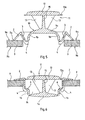
- the insertion force exerted on the dome 1 makes it turn inside out so that its concave shape is inverted.
- These slots 5 also allow the expansion of the annular part 3 between the starting position and the locking position of the obturator.
- the connecting portion 6 of the dome 1 and of the annular part 3 has a cross section shaped as an S.
- This connecting portion 6 thus forms a hinge around which the wall 1b of the dome 1 pivots upon its being turned inside out.
- the dome 1 exerts a tensile force on the expanded annular part 3, at the level of the connecting portion 6, and contributes towards keeping the teeth 4 against the said opposite face 9b of the aperture 8. Moreover, the lip 2 is kept in abutment against the face 9a of the aperture so as to guarantee tightness.
- the face 10 of the central portion 1a of the dome 1 is then domed towards the interior of the dome 1 turned inside out in this locking position, so that the force exerted by this central portion la on the walls 1b of the dome and transmitted to the annular part 3 is increased.
- a reliable attachment of the obturator in the aperture 8 is achieved, with the operator also being informed of the obturation by the noise which the turning inside out of the dome in the metal structure bearing the aperture can generate.
- the obturator also comprises a plug 11 fixed to the dome 1.
- This plug 11 comprises a substantially plane cap-forming portion 12 fixed by means of a central rod 15 onto the central portion la of the dome 1.
- Reinforcing ribs 13 extend between the dome 1 and the cap-forming portion 12 so as to strengthen the attachment of the plug 11 onto the dome 1.
- the cap-forming portion 12 comprises a deformable peripheral rim 12a.
- the cap-forming portion 12 has a periphery of reduced thickness which thus forms a flexible peripheral rim 12a.
- the plug 11 is circular in shape and is also moulded in a single piece with the dome 1 in the starting position illustrated in Figure 5.
- the plug 11 closes the cavity 14 formed by the dome turned inside out and the annular part 3.
- This closing is achieved simultaneously with the locking of the obturator in the aperture 8 of the metal sheet 9.
- the peripheral rim 12a of the cap-forming portion 12 is slightly deformed between the cap-forming portion 12 and the peripheral lip 2 abutting against the face 9a of the aperture.
- This peripheral rim 12a thus forms a sealing lip which enables the sound-proofing function of the obturator to be reinforced. This seal may be obtained even if slight dimensional differences exist from one aperture to another or from one obturator to another.
- the cap-forming portion 12 and the peripheral lip 2 extend substantially in the same plane so as to better limit any thicker part on the metal sheet 9.
- the shoulders could be limited to two teeth disposed symmetrically on the annular part or even be formed by a single peripheral crown forming a continuous shoulder adapted to be housed under the periphery of the aperture.
Landscapes
- Engineering & Computer Science (AREA)
- Chemical & Material Sciences (AREA)
- Combustion & Propulsion (AREA)
- Transportation (AREA)
- Mechanical Engineering (AREA)
- Pressure Vessels And Lids Thereof (AREA)
- Closures For Containers (AREA)
- Gasket Seals (AREA)
Applications Claiming Priority (4)
| Application Number | Priority Date | Filing Date | Title |
|---|---|---|---|
| FR9808825 | 1998-07-09 | ||
| FR9808825A FR2780952A1 (fr) | 1998-07-09 | 1998-07-09 | Obturateur pour une ouverture realisee dans une tole |
| FR9814407 | 1998-11-17 | ||
| FR9814407A FR2780953B1 (fr) | 1998-07-09 | 1998-11-17 | Obturateur pour une ouverture realisee dans une tole |
Publications (1)
| Publication Number | Publication Date |
|---|---|
| EP0970878A1 true EP0970878A1 (de) | 2000-01-12 |
Family
ID=26234435
Family Applications (1)
| Application Number | Title | Priority Date | Filing Date |
|---|---|---|---|
| EP99401427A Withdrawn EP0970878A1 (de) | 1998-07-09 | 1999-06-11 | Stopfen für eine Öffnung in einer Metallplatte |
Country Status (4)
| Country | Link |
|---|---|
| US (1) | US6296136B1 (de) |
| EP (1) | EP0970878A1 (de) |
| CA (1) | CA2276519C (de) |
| FR (1) | FR2780953B1 (de) |
Cited By (11)
| Publication number | Priority date | Publication date | Assignee | Title |
|---|---|---|---|---|
| FR2796367A1 (fr) * | 1999-07-13 | 2001-01-19 | Itw De France | Obturateur pour une ouverture realisee dans une tole |
| FR2805503A1 (fr) * | 2000-02-28 | 2001-08-31 | Itw De France | Obturateur pour une ouverture realisee dans une tole |
| EP1298037A3 (de) * | 2001-10-01 | 2003-11-05 | ITW Automotive Products GmbH & Co. KG | Verschlussstopfen für ein Loch im Blech einer Karrosserie oder Boden eines Fahrzeuges |
| EP1426272A3 (de) * | 2002-12-02 | 2004-07-28 | TRW Automotive Electronics & Components GmbH & Co. KG | Einstückiger Verschlussdeckel |
| WO2005019547A1 (de) * | 2003-08-13 | 2005-03-03 | Aco Severin Ahlmann Gmbh & Co. Kg | Abdeckungsanordnung |
| FR2869865A1 (fr) * | 2004-05-10 | 2005-11-11 | Renault Sas | Dispositif d'obturation d'orifice d'une paroi de vehicule automobile |
| WO2009000559A1 (de) * | 2007-06-22 | 2008-12-31 | Koenig Verbindungstechnik Ag | Verschlusselement für bohrungen |
| DE102009055861A1 (de) * | 2009-11-26 | 2011-06-22 | Praetorius, Max, 91239 | Abdeckung von Schraubenbohrungen |
| WO2013026458A1 (de) * | 2011-08-23 | 2013-02-28 | Kvt-Koenig Ag | Verschlusselement für innendruckbeanspruchte bohrungen |
| CN103189674A (zh) * | 2010-09-03 | 2013-07-03 | 株式会社利富高 | 孔塞 |
| EP2873894A1 (de) * | 2013-11-15 | 2015-05-20 | TRW Automotive Electronics & Components GmbH | Verschlussstopfen |
Families Citing this family (36)
| Publication number | Priority date | Publication date | Assignee | Title |
|---|---|---|---|---|
| US6380489B1 (en) * | 2000-09-02 | 2002-04-30 | Arlington Industries, Inc. | Stud bushing |
| DE20107612U1 (de) * | 2001-05-04 | 2001-10-18 | TRW Automotive Electronics & Components GmbH & Co. KG, 78315 Radolfzell | Verschlussdeckel |
| US6789741B2 (en) * | 2002-03-27 | 2004-09-14 | S. C. Johnson & Son, Inc. | Method and apparatus for atomizing liquids having minimal droplet size |
| DE20209513U1 (de) * | 2002-06-19 | 2002-08-29 | TRW Automotive Electronics & Components GmbH & Co. KG, 78315 Radolfzell | Verschlussdeckel |
| US6883679B2 (en) * | 2002-10-30 | 2005-04-26 | L. L. Culmat L.P. | Snap-insert hole closing plug |
| US20060081300A1 (en) * | 2004-10-14 | 2006-04-20 | Schmalz Gregory P | Apparatus for capping plumbing vent pipes during pressure testing |
| US7455192B2 (en) * | 2004-11-03 | 2008-11-25 | Illinois Tool Works Inc. | Overmolded adhesive hole plug |
| DE102006007914B4 (de) * | 2006-02-16 | 2008-02-28 | Itw Automotive Products Gmbh & Co. Kg | Verschlussstopfen mit Druckausgleichskammer |
| US9517865B2 (en) * | 2007-10-09 | 2016-12-13 | Oliver Albers | Airtight canister lid with flexible seal-breaking bulb |
| JP5243914B2 (ja) * | 2008-10-08 | 2013-07-24 | 株式会社ニフコ | ホールプラグ |
| US8355799B2 (en) | 2008-12-12 | 2013-01-15 | Arthrocare Corporation | Systems and methods for limiting joint temperature |
| DE102009014640A1 (de) * | 2009-03-24 | 2010-10-07 | Hans Schell Gmbh & Co. Kg | Schutzvorrichtung zur Abdeckung von Flanschen für den Rohrleitungsbau |
| GB2488267B (en) | 2009-12-07 | 2016-06-08 | Arthrocare Corp | Single aperture electrode assembly |
| US8672178B2 (en) * | 2010-04-20 | 2014-03-18 | Illinois Tool Works Inc. | Hole plug assembly |
| US8696659B2 (en) | 2010-04-30 | 2014-04-15 | Arthrocare Corporation | Electrosurgical system and method having enhanced temperature measurement |
| US8979838B2 (en) | 2010-05-24 | 2015-03-17 | Arthrocare Corporation | Symmetric switching electrode method and related system |
| US8685018B2 (en) | 2010-10-15 | 2014-04-01 | Arthrocare Corporation | Electrosurgical wand and related method and system |
| US10448992B2 (en) | 2010-10-22 | 2019-10-22 | Arthrocare Corporation | Electrosurgical system with device specific operational parameters |
| MX2014004460A (es) | 2011-10-12 | 2014-08-01 | Sonoco Dev Inc | Tapa de sellado para un contenedor. |
| JP5921353B2 (ja) * | 2011-11-16 | 2016-05-24 | 株式会社ニフコ | ホールプラグ |
| US9254166B2 (en) | 2013-01-17 | 2016-02-09 | Arthrocare Corporation | Systems and methods for turbinate reduction |
| US9713489B2 (en) | 2013-03-07 | 2017-07-25 | Arthrocare Corporation | Electrosurgical methods and systems |
| GB2514231B (en) | 2013-03-14 | 2016-04-06 | Arthrocare Corp | Fine dissection electrosurgical device |
| US10420607B2 (en) | 2014-02-14 | 2019-09-24 | Arthrocare Corporation | Methods and systems related to an electrosurgical controller |
| US9597142B2 (en) | 2014-07-24 | 2017-03-21 | Arthrocare Corporation | Method and system related to electrosurgical procedures |
| US10993765B2 (en) | 2015-06-30 | 2021-05-04 | Smith & Nephew, Inc. | Temperature measurement of electrically conductive fluids |
| AU2018250540B2 (en) | 2017-04-10 | 2023-09-21 | Smith & Nephew, Inc. | Plasma surgery device |
| US20210169565A1 (en) | 2017-05-16 | 2021-06-10 | Smith & Nephew, Inc. | Electrosurgical systems and methods |
| US10336517B1 (en) * | 2018-01-08 | 2019-07-02 | Rodney Laible | Tamper-proof container insert |
| US10301088B1 (en) * | 2018-01-08 | 2019-05-28 | Rodney Laible | Tamper-proof container insert |
| EP3921245B1 (de) * | 2019-02-05 | 2022-09-21 | Unilever Global Ip Limited | Stöpselverschluss |
| US12274493B2 (en) | 2019-02-22 | 2025-04-15 | Smith & Nephew, Inc. | Combination electrosurgical and mechanical resection device |
| CN118453103A (zh) | 2019-12-19 | 2024-08-09 | 史密夫和内修有限公司 | 用于鼻甲缩减的系统和方法 |
| US11421719B2 (en) * | 2020-01-10 | 2022-08-23 | Illinois Tool Works Inc. | Fastening clip with visual seal |
| WO2021226340A1 (en) | 2020-05-06 | 2021-11-11 | Smith & Nephew, Inc. | Electrosurgical device |
| US20220381343A1 (en) * | 2021-05-31 | 2022-12-01 | Illinois Tool Works Inc. | Sealing Plug |
Citations (5)
| Publication number | Priority date | Publication date | Assignee | Title |
|---|---|---|---|---|
| GB1354973A (en) * | 1970-09-01 | 1974-06-05 | Itw Ateco Gmbh | Plugs |
| US3900130A (en) * | 1972-01-26 | 1975-08-19 | Trw Inc | Insert for securing in a hole |
| FR2395203A1 (fr) * | 1977-06-23 | 1979-01-19 | Itw De France | Bouchon de securite insonorisant |
| DE3139968A1 (de) * | 1981-10-08 | 1983-04-28 | Itw-Ateco Gmbh, 2000 Norderstedt | "lochstopfen" |
| DE3902500A1 (de) * | 1989-01-27 | 1990-08-02 | United Carr Gmbh Trw | Verschlussdeckel |
Family Cites Families (29)
| Publication number | Priority date | Publication date | Assignee | Title |
|---|---|---|---|---|
| USRE25906E (en) * | 1965-11-16 | Cover and container | ||
| US849243A (en) * | 1904-06-21 | 1907-04-02 | Max I Manowitz | Closure for bottles, &c. |
| US1085262A (en) * | 1911-10-27 | 1914-01-27 | American Steel Foundries | Spring-cap for coupling-lifter holes. |
| US2228435A (en) * | 1937-11-10 | 1941-01-14 | Food Dispenser Company | Dispenser for viscous liquids |
| US2396035A (en) * | 1942-08-08 | 1946-03-05 | Simmonds Dev Corp Ltd | Stopper |
| US2487635A (en) * | 1945-03-05 | 1949-11-08 | Carpenter Hazel Cecil | Snaptite stopper |
| US2649090A (en) * | 1950-09-29 | 1953-08-18 | American Cyanamid Co | Rubber closure for pharmaceutical vials |
| AT218842B (de) * | 1959-08-29 | 1961-12-27 | Josef Ess O H G | Vakuum-Frischhaltegefäß |
| FR1418151A (fr) * | 1964-10-05 | 1965-11-19 | Couvercle à fermeture instantanée | |
| US3380610A (en) * | 1966-10-13 | 1968-04-30 | Container Corp | Snap-on lid for plastic container |
| US3438536A (en) * | 1966-11-29 | 1969-04-15 | Heinemann Electric Ltd | Removable covers |
| US3430777A (en) * | 1967-06-22 | 1969-03-04 | Vincent J Esposito Jr | Pilferproof cap with integral pressure actuated sealing means |
| US3586197A (en) * | 1969-09-23 | 1971-06-22 | Humberto Vivas | Disposable container cap |
| US3742898A (en) * | 1972-08-10 | 1973-07-03 | Noyce R | Pressure indicating bung with self-locking insertion feature |
| US3982649A (en) * | 1975-01-30 | 1976-09-28 | Denver Plastics, Inc. | Bung for a barrel |
| US4027776A (en) * | 1975-07-31 | 1977-06-07 | Avon Products, Inc. | Recloseable container |
| US4053084A (en) * | 1976-03-01 | 1977-10-11 | Illinois Tool Works Inc. | Filler plug |
| US4227625A (en) * | 1979-08-17 | 1980-10-14 | Underwood James L | Sealing lid and sealing lid-container combination |
| US4287996A (en) * | 1979-10-09 | 1981-09-08 | Denver Plastics, Inc. | Flexible closures and closure for bung openings |
| JPH028867Y2 (de) * | 1980-03-03 | 1990-03-02 | ||
| US4504009A (en) * | 1980-06-24 | 1985-03-12 | The Continental Group, Inc. | Closure having means for retention in tubular container |
| US4413748A (en) * | 1982-07-22 | 1983-11-08 | Kessler Products Co., Inc. | Pinch cap |
| US4691836A (en) * | 1983-01-06 | 1987-09-08 | Victor Wassilieff | Apertured closure device with depressible disc portion |
| US4463870A (en) * | 1983-10-19 | 1984-08-07 | L & L Products, Inc. | Closure plate for an opening |
| DE3512582C3 (de) * | 1985-04-06 | 1997-03-13 | Itw Ateco Gmbh | Lochstopfen, insbesondere zum Abdichten von Lackauslauflöchern in Karosserien von Kraftfahrzeugen |
| US4620641A (en) * | 1985-12-12 | 1986-11-04 | General Motors Corporation | Access plug for threaded holes in electric starting apparatus |
| DE3817896A1 (de) * | 1988-05-26 | 1989-12-07 | United Carr Gmbh Trw | Verschlussdeckel aus kunststoff, insbesondere zum verschliessen einer oeffnung in einer kraftfahrzeugkarosserie |
| US5709309A (en) * | 1994-11-07 | 1998-01-20 | Ford Global Technologies, Inc. | Orifice drain stop |
| JP2000041320A (ja) * | 1998-05-20 | 2000-02-08 | Yazaki Corp | グロメット |
-
1998
- 1998-11-17 FR FR9814407A patent/FR2780953B1/fr not_active Expired - Fee Related
-
1999
- 1999-06-11 EP EP99401427A patent/EP0970878A1/de not_active Withdrawn
- 1999-06-25 CA CA002276519A patent/CA2276519C/en not_active Expired - Fee Related
- 1999-07-08 US US09/349,255 patent/US6296136B1/en not_active Expired - Lifetime
Patent Citations (5)
| Publication number | Priority date | Publication date | Assignee | Title |
|---|---|---|---|---|
| GB1354973A (en) * | 1970-09-01 | 1974-06-05 | Itw Ateco Gmbh | Plugs |
| US3900130A (en) * | 1972-01-26 | 1975-08-19 | Trw Inc | Insert for securing in a hole |
| FR2395203A1 (fr) * | 1977-06-23 | 1979-01-19 | Itw De France | Bouchon de securite insonorisant |
| DE3139968A1 (de) * | 1981-10-08 | 1983-04-28 | Itw-Ateco Gmbh, 2000 Norderstedt | "lochstopfen" |
| DE3902500A1 (de) * | 1989-01-27 | 1990-08-02 | United Carr Gmbh Trw | Verschlussdeckel |
Cited By (22)
| Publication number | Priority date | Publication date | Assignee | Title |
|---|---|---|---|---|
| FR2796367A1 (fr) * | 1999-07-13 | 2001-01-19 | Itw De France | Obturateur pour une ouverture realisee dans une tole |
| US6634840B1 (en) | 1999-07-13 | 2003-10-21 | I.T.W. De France | Obturator for an opening produced in a metal sheet |
| FR2805503A1 (fr) * | 2000-02-28 | 2001-08-31 | Itw De France | Obturateur pour une ouverture realisee dans une tole |
| JP2001271930A (ja) * | 2000-02-28 | 2001-10-05 | Itw De France | 密閉装置 |
| USRE39654E1 (en) | 2000-02-28 | 2007-05-29 | I.T.W. De France | Obturator for an opening produced in a metal sheet |
| EP1298037A3 (de) * | 2001-10-01 | 2003-11-05 | ITW Automotive Products GmbH & Co. KG | Verschlussstopfen für ein Loch im Blech einer Karrosserie oder Boden eines Fahrzeuges |
| EP1426272A3 (de) * | 2002-12-02 | 2004-07-28 | TRW Automotive Electronics & Components GmbH & Co. KG | Einstückiger Verschlussdeckel |
| WO2005019547A1 (de) * | 2003-08-13 | 2005-03-03 | Aco Severin Ahlmann Gmbh & Co. Kg | Abdeckungsanordnung |
| FR2869865A1 (fr) * | 2004-05-10 | 2005-11-11 | Renault Sas | Dispositif d'obturation d'orifice d'une paroi de vehicule automobile |
| WO2009000337A1 (de) * | 2007-06-22 | 2008-12-31 | Koenig Verbindungstechnik Ag | Verschlusselement für bohrungen |
| WO2009000559A1 (de) * | 2007-06-22 | 2008-12-31 | Koenig Verbindungstechnik Ag | Verschlusselement für bohrungen |
| WO2009000317A1 (de) * | 2007-06-22 | 2008-12-31 | Koenig Verbindungstechnik Ag | Verschlusselement für bohrungen |
| DE102009055861A1 (de) * | 2009-11-26 | 2011-06-22 | Praetorius, Max, 91239 | Abdeckung von Schraubenbohrungen |
| DE102009055861B4 (de) * | 2009-11-26 | 2013-12-19 | Max Praetorius | Abdeckung von Schraubenbohrungen |
| CN103189674A (zh) * | 2010-09-03 | 2013-07-03 | 株式会社利富高 | 孔塞 |
| CN103189674B (zh) * | 2010-09-03 | 2015-08-12 | 株式会社利富高 | 孔塞 |
| WO2013026458A1 (de) * | 2011-08-23 | 2013-02-28 | Kvt-Koenig Ag | Verschlusselement für innendruckbeanspruchte bohrungen |
| CN103857953A (zh) * | 2011-08-23 | 2014-06-11 | Kvt-科尼格股份公司 | 用于受内压力的孔的封闭元件 |
| US9366374B2 (en) | 2011-08-23 | 2016-06-14 | Kvt-Koenig Ag | Closure element for bores subjected to internal pressure |
| RU2601047C2 (ru) * | 2011-08-23 | 2016-10-27 | Квт-Коениг Аг | Запорный элемент для запирания отверстия, подвергающийся действию внутреннего давления |
| CN103857953B (zh) * | 2011-08-23 | 2017-11-07 | Sfc柯尼希股份公司 | 用于受内压力的孔的封闭元件 |
| EP2873894A1 (de) * | 2013-11-15 | 2015-05-20 | TRW Automotive Electronics & Components GmbH | Verschlussstopfen |
Also Published As
| Publication number | Publication date |
|---|---|
| CA2276519A1 (en) | 2000-01-09 |
| CA2276519C (en) | 2003-09-23 |
| FR2780953A1 (fr) | 2000-01-14 |
| FR2780953B1 (fr) | 2000-09-29 |
| US6296136B1 (en) | 2001-10-02 |
Similar Documents
| Publication | Publication Date | Title |
|---|---|---|
| CA2276519C (en) | Obturator for an aperture produced in a metal sheet | |
| USRE39654E1 (en) | Obturator for an opening produced in a metal sheet | |
| US6623067B2 (en) | Door seal interface structure for a motor vehicle space frame | |
| US5739475A (en) | Grommet for protecting a wire harness with structure for ensuring flush seating | |
| US5402901A (en) | Closure device for a recipient | |
| AU634628B2 (en) | Butt connections between two air duct sections made of sheet metal | |
| JPS622196B2 (de) | ||
| GB2051661A (en) | Hollow bodies having inserts | |
| JP3594655B2 (ja) | オイルレベルゲージ | |
| JPH06147381A (ja) | 車両用パイプ−コンテナ継手組立体 | |
| US5701634A (en) | Grommet | |
| US5507500A (en) | Expandable compression ring with locking members | |
| GB2221611A (en) | Wind screen wiper pivot joint | |
| US20040083884A1 (en) | Brake servo comprising a connecting element with a defined angular position | |
| US5732955A (en) | Expandable compression ring | |
| JPH0927226A (ja) | グロメット | |
| US5398979A (en) | Seal for manholes and drains | |
| JP3888214B2 (ja) | ロータンクの蓋の取り付け構造 | |
| JP3531235B2 (ja) | ステアリングコラムカバー | |
| JPS6032461Y2 (ja) | 球接手用ダストブ−ツ | |
| JPS629072Y2 (de) | ||
| JPH0534259Y2 (de) | ||
| JPH067270Y2 (ja) | 高外圧条件下に適した管継手機構 | |
| KR102622798B1 (ko) | 양변기의 배수통로 연결장치 | |
| JPH0953780A (ja) | 配管接続構造 |
Legal Events
| Date | Code | Title | Description |
|---|---|---|---|
| PUAI | Public reference made under article 153(3) epc to a published international application that has entered the european phase |
Free format text: ORIGINAL CODE: 0009012 |
|
| AK | Designated contracting states |
Kind code of ref document: A1 Designated state(s): DE FR GB |
|
| AX | Request for extension of the european patent |
Free format text: AL;LT;LV;MK;RO;SI |
|
| 17P | Request for examination filed |
Effective date: 20000226 |
|
| AKX | Designation fees paid |
Free format text: DE FR GB |
|
| STAA | Information on the status of an ep patent application or granted ep patent |
Free format text: STATUS: THE APPLICATION IS DEEMED TO BE WITHDRAWN |
|
| 18D | Application deemed to be withdrawn |
Effective date: 20020103 |