EP0970899A1 - Procédé et appareil pour traiter des objets, en particulier des objets en forme de tranches comme des tôles, vitres, circuits imprimés, substrats céramiques - Google Patents
Procédé et appareil pour traiter des objets, en particulier des objets en forme de tranches comme des tôles, vitres, circuits imprimés, substrats céramiques Download PDFInfo
- Publication number
- EP0970899A1 EP0970899A1 EP99112429A EP99112429A EP0970899A1 EP 0970899 A1 EP0970899 A1 EP 0970899A1 EP 99112429 A EP99112429 A EP 99112429A EP 99112429 A EP99112429 A EP 99112429A EP 0970899 A1 EP0970899 A1 EP 0970899A1
- Authority
- EP
- European Patent Office
- Prior art keywords
- objects
- bath
- cheeks
- rotating device
- transport
- Prior art date
- Legal status (The legal status is an assumption and is not a legal conclusion. Google has not performed a legal analysis and makes no representation as to the accuracy of the status listed.)
- Granted
Links
- 238000000034 method Methods 0.000 title claims description 12
- 239000000758 substrate Substances 0.000 title claims description 9
- 239000000919 ceramic Substances 0.000 title claims description 8
- 238000001035 drying Methods 0.000 claims abstract description 32
- 239000007788 liquid Substances 0.000 claims abstract description 24
- 238000005406 washing Methods 0.000 claims abstract description 14
- 239000000126 substance Substances 0.000 claims abstract description 11
- 238000004140 cleaning Methods 0.000 claims description 23
- 239000011521 glass Substances 0.000 claims description 7
- 239000007921 spray Substances 0.000 claims description 5
- 230000002093 peripheral effect Effects 0.000 claims description 4
- 238000012546 transfer Methods 0.000 claims description 4
- 239000012530 fluid Substances 0.000 claims description 3
- 238000011144 upstream manufacturing Methods 0.000 claims description 3
- 239000002184 metal Substances 0.000 claims description 2
- 230000032258 transport Effects 0.000 claims 10
- 230000000717 retained effect Effects 0.000 claims 2
- XLYOFNOQVPJJNP-UHFFFAOYSA-N water Substances O XLYOFNOQVPJJNP-UHFFFAOYSA-N 0.000 description 7
- KRHYYFGTRYWZRS-UHFFFAOYSA-N Fluorane Chemical compound F KRHYYFGTRYWZRS-UHFFFAOYSA-N 0.000 description 4
- 230000006378 damage Effects 0.000 description 4
- 238000010924 continuous production Methods 0.000 description 3
- 230000014759 maintenance of location Effects 0.000 description 3
- 230000001360 synchronised effect Effects 0.000 description 3
- 238000005530 etching Methods 0.000 description 2
- 238000005192 partition Methods 0.000 description 2
- 239000004065 semiconductor Substances 0.000 description 2
- 238000005507 spraying Methods 0.000 description 2
- 239000004094 surface-active agent Substances 0.000 description 2
- 235000012431 wafers Nutrition 0.000 description 2
- 206010013786 Dry skin Diseases 0.000 description 1
- 230000000712 assembly Effects 0.000 description 1
- 238000000429 assembly Methods 0.000 description 1
- 238000010586 diagram Methods 0.000 description 1
- 238000006073 displacement reaction Methods 0.000 description 1
- 230000000694 effects Effects 0.000 description 1
- 238000005187 foaming Methods 0.000 description 1
- 230000010354 integration Effects 0.000 description 1
- 230000007723 transport mechanism Effects 0.000 description 1
Images
Classifications
-
- H—ELECTRICITY
- H05—ELECTRIC TECHNIQUES NOT OTHERWISE PROVIDED FOR
- H05K—PRINTED CIRCUITS; CASINGS OR CONSTRUCTIONAL DETAILS OF ELECTRIC APPARATUS; MANUFACTURE OF ASSEMBLAGES OF ELECTRICAL COMPONENTS
- H05K3/00—Apparatus or processes for manufacturing printed circuits
- H05K3/0085—Apparatus for treatments of printed circuits with liquids not provided for in groups H05K3/02 - H05K3/46; conveyors and holding means therefor
-
- B—PERFORMING OPERATIONS; TRANSPORTING
- B65—CONVEYING; PACKING; STORING; HANDLING THIN OR FILAMENTARY MATERIAL
- B65G—TRANSPORT OR STORAGE DEVICES, e.g. CONVEYORS FOR LOADING OR TIPPING, SHOP CONVEYOR SYSTEMS OR PNEUMATIC TUBE CONVEYORS
- B65G49/00—Conveying systems characterised by their application for specified purposes not otherwise provided for
- B65G49/02—Conveying systems characterised by their application for specified purposes not otherwise provided for for conveying workpieces through baths of liquid
- B65G49/04—Conveying systems characterised by their application for specified purposes not otherwise provided for for conveying workpieces through baths of liquid the workpieces being immersed and withdrawn by movement in a vertical direction
- B65G49/0409—Conveying systems characterised by their application for specified purposes not otherwise provided for for conveying workpieces through baths of liquid the workpieces being immersed and withdrawn by movement in a vertical direction specially adapted for workpieces of definite length
- B65G49/0413—Conveying systems characterised by their application for specified purposes not otherwise provided for for conveying workpieces through baths of liquid the workpieces being immersed and withdrawn by movement in a vertical direction specially adapted for workpieces of definite length arrangements for conveyance through the bath
Definitions
- the invention relates to a method for treating objects, in particular disc-shaped objects such as sheets, glass plates, printed circuit boards, ceramic substrates, wherein the objects are fed to a liquid-containing bath by means of a Rotating device with permanent alignment of the objects to the axis of rotation of the Rotating device rotated around it and transported through the bath and after the bath be carried away translationally, with the objects during their transport the bath in receptacles of the rotating device which run radially with respect to the axis of rotation are held back by a peripherally surrounding fuse.
- a device for treating objects comprising a liquid fillable bath such as a chemical bath for treating the Objects, a feed device upstream of the bath, the objects through the Bath conveying device in the form of a rotating device with radially extending Inclusion of the objects certain recordings, one existing within the bath Securing, which is in the peripheral area of the recordings for holding back the objects extends in the recordings, a removal device downstream of the bath and the Subsequent washing and / or drying stage with associated transport device.
- a liquid fillable bath such as a chemical bath for treating the Objects
- a feed device upstream of the bath the objects through the Bath conveying device in the form of a rotating device with radially extending Inclusion of the objects certain recordings, one existing within the bath Securing, which is in the peripheral area of the recordings for holding back the objects extends in the recordings
- a removal device downstream of the bath downstream of the bath and the Subsequent washing and / or drying stage with associated transport device.
- oxide layers of semiconductor wafers by etching in dilute
- hydrofluoric acid it is known to place the discs in plastic trays and these then manually or with a handling device in succession in different immerse chemical baths or spray them with chemicals.
- Disadvantage of this procedure is that putting the disks in the hordes and taking out the Make slices from these additional process steps necessary, especially then are undesirable if those preceding or following the chemical treatment Processes should run continuously.
- Another disadvantage of the known method is that the supply of chemicals is too the discs to be treated is limited by the hordes. Furthermore, when Drying liquid like water as well as chemical residues remain in the pockets of the hordes, unless complex drying processes are used.
- the pulleys are moved by means of a belt conveyor or conveyor belt passed through a spray device in which spraying with chemicals he follows. Spraying does not ensure that the panes on the one hand be completely wetted and on the other hand the duration of treatment is limited or required systems must be very voluminous.
- DE-PS 639 104 shows a device for treating sheet metal through a bath filled with liquid.
- the planar Objects picked up by a rotating device and guided through the bath.
- Behind the Bad is a transport device with which the objects are translated become.
- the objects are fed from the stack to the rotating device itself.
- stationary guide strips run peripherally to the rotating device, along the slide the sheets to ensure that the sheets remain in the rotator.
- a transport device is known from EP 0 070 694 A1, in which objects such as Versions are transported using a turntable, the circumference of one Endless belt is surrounded.
- the turntable itself is about a vertical axis of rotation rotatable.
- the objects are relative to one in the entrance area of the turntable fixed guide plate moves.
- a spoke wheel transport device to be found in DE-OS 1 951 200 sees one Conveyor in the form of a spoke wheel to cool slabs.
- the problem underlying the present invention is a method and a device of the type mentioned at the outset in such a way that, in addition to integration into a Continuous process ensures that the items are to the required extent can be supplied with the liquid required for the treatment without a Damage occurs. In particular, relationship movements between the objects and the rotating device are prevented when the objects are guided through the bath.
- the problem is solved by a method in that the objects during transport through the bathroom using a flexible element as a safety device the recording, which is moved synchronously with the rotating device, that the objects are fed radially to the rotating device via a transport hand and that the objects after leaving the bathroom at least one washing and / or Drying level can be supplied.
- the objects become radial to the axis of rotation introduced recordings of a rotary conveyor, the objects are secured away from the axis of rotation while being guided through the bath. Things itself can use the rotary conveyor like turning wheel on a conveyor belt like belt conveyor fed and / or led away from this.
- the backup takes place via a synchronized with the rotary conveyor and moving within the floor peripherally surrounding flexible element, whereby a relationship movement between the Objects and the fuse and thus an otherwise possible damage to thin objects is prevented.
- a is carried out in a continuous or quasi-continuous process Transfer of the objects from a first conveyor such as a belt conveyor to the Rotating device, which can be called a modified turning wheel, by means of which the Objects are passed through the bath, then to another translatory conveyor such as a conveyor belt or belt conveyor. Then they can Objects are fed to a washing and / or drying stage.
- a first conveyor such as a belt conveyor
- the Rotating device which can be called a modified turning wheel
- a device of the type mentioned is characterized in that the fuse is a flexible element moving synchronously with the rotating device.
- the rotating device in particular comprises two spaced apart from one of common shaft passing through the axis with outgoing cheeks with respect to the axis slots open radially to the periphery as receptacles.
- the cheeks themselves are preferably designed as circular disks and have openings on.
- Retaining element On the outside along each cheek there should be a side emitting from the shaft Retaining element may be arranged as a washer, preferably with the respective cheek is connected.
- the corresponding retention elements ensure that the objects within the slots are not axially displaceable to an unacceptable extent.
- the circumference along the Cheek like circular disc, flexible element covering the receptacle facing away from the axis Belt provided, which is moved synchronously with the rotating device. It is flexible element in particular an endless belt that runs over deflection rollers to the edge Concerns on the cheeks in the bathroom. Because of the synchronous movements a relationship movement between the security and the objects during their No transport through the bathroom. Thus, especially with thin and / or sensitive objects such as glass plates or ceramic substrates ensure that a No damage or destruction.
- At least two rotating devices can be used from the shaft go out, between adjacent cheeks of successive rotating devices one retention element each runs. This makes a device-like Simplification achieved.
- the receptacles for the objects which are designed as radial slots, are in particular peripherally evenly distributed on the cheek of the disc. Also exists the possibility that the device with several baths arranged in series one behind the other through these the objects conveying rotating devices.
- the feed device for the turning device to be designated as a turning wheel and / or the a removal device downstream of the rotating device should be a translatory transport device be like belt conveyors.
- the respective transport device can either give up or remove from this during the transfer or removal in the area between the side cheeks the rotating device can be moved. After delivering or picking up the items the corresponding transport device is then withdrawn.
- the objects from the feed device to the Rotating device or from this to the removal device via at least one parallel to the conveyor and to this reciprocable driver are recorded, the preferably runs between the cheeks of a rotating device.
- the Carrier can also be raised or lowered.
- the driver By using the driver to be designated as a slide, the objects can be easily pushed into or out of the rotating device, the respective associated transport devices spaced at the end face from the peripheral one Area of the cheeks are arranged. This also has the advantage that the driver or slide do not come into contact with the liquid, so that there is no carry-over of chemicals in particular via the transport facilities outside the Bades is to be feared.
- the objects should be in the cleaning and / or drying stage downstream of the bathroom also via a translatory conveyor such as a belt conveyor or walking beam conveyor be moved.
- a translatory conveyor such as a belt conveyor or walking beam conveyor be moved.
- Each conveyor is divided into sections, on which the objects are supported in different areas. This gives the advantage that a complete cleaning or drying of the objects during the Passing through the cleaning or drying stage is guaranteed.
- To lift the objects while they are being cleaned and / or to prevent drying air can be arranged above the transport path of the cleaning and / or drying stage rollers aligned to the conveyor over which the objects are pressurized.
- Spray nozzles are directed at the objects in the transport section of the cleaning stage and / or surge devices arranged to easily the required To achieve cleaning.
- the cleaning stage itself can be designed in several stages.
- the cleaning fluid required for each cleaning stage flows in a circuit, whereby Circuits for the same cleaning liquids are cascaded.
- the drying stage itself has, in particular, air nozzles and knives that point towards the drying objects are aligned.
- the transport path can have at least one suction device be assigned.
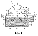
- Fig. 1 a schematic representation of a conveyor 10 is shown by means of the objects 12 are to be conveyed through a bath 16 containing a liquid 14 in order, for. B. etch away surfaces.
- a bath 16 containing a liquid 14 in order, for. B. etch away surfaces.
- This is for example in the case of semiconductor wafers as flat objects 12 possible with dilute hydrofluoric acid.
- this is the one according to the invention Teaching not limited. Rather, it extends to objects of any kind, in particular, however, on plate-shaped objects such as sheets, glass plates, printed circuit boards, Ceramic substrates etc.
- the bath 16 comprises a basin 18, which is separated by a partition 20 with a storage tank 22 from which the liquid is continuously circulated, the liquid level 24 is predetermined by the upper edge of the partition 20. This ensures that the same liquid level 26 is always present in the bath 18.
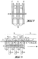
- the conveying device 10 extends within the bath 16, ie the liquid 14 is designed as a "turning wheel". This means that a shaft 28 is spaced apart from one another disc-shaped elements 30, 32 and 34, 36 (Fig. 2) go out by the Shaft 28 predetermined axis are rotatable together. Peripher of the circumference of the disks 32, 34, 36 emanate radially extending slots, which are identified by way of example with the reference symbols 38, 40 are provided. The slots 38, 40 serve as receptacles for the objects 12, the promoted by the bath 18 and to be treated there.
- the same shaft 28 extends between one another Conveyors 10, which are formed by the disks 30, 32 and 34, 36, only one Retaining element 44 or disc present.
- the limiting disks 42, 44, 46 should also have the respective cheeks 30, 32, 34, 36 are connected via webs. Finally, the cheeks 30, 32, 34, 36 as well the retaining disks 42, 44, 46 have openings as required.
- a belt conveyor 48 is provided in the exemplary embodiment, via which the Objects 12 - in the illustration according to FIG. 1 from left to right - to a slot in the exemplary embodiment, the slot 40 is to be transferred. So that the belt conveyor 48, which can also be replaced by another conveying element without leaving the invention is not into the area between the cheeks 30, 32 or 34, 36 during the transfer must be adjusted, a driver or runs between the cheeks 30, 32 or 34, 36 Slider 50, which is both parallel to the conveyor path of the conveyor 48 and one of the rotating device 10 downstream conveyor 52 and preferably perpendicular or oblique to these is adjustable, as arrows 54 and 56 are intended to illustrate.
- an article 12 can be slotted 38 onto the conveyor 52 when aligned the slot 38 are passed on the conveyor line if the in the illustration right leg 58 of the driver 50 starting from the inner end of the slot 38 is adjusted radially outward in the transport direction 54, whereby the object 12 on the Conveyor belt 52 is passed.
- an endless belt 60 is provided, which has pulleys 62, 64, 66, 68 is guided so peripherally along the peripheral edge of the disk or wheel 30 that the slots 38, 40 are covered on the outside to the required extent. This is based on of the representations according to FIG. 1 and FIG. 2 clearly.
- the endless belt 60 or one element having the same effect is moved synchronously with the rotating device in such a way that when transported through the bath 14 between the objects 12 and the fuse in Support area a relationship movement is prevented.
- the disc element 30, 32, 34, 36 should have a recess on the outside edge such as groove, which serves as a guide for the belt 60 and ensures that this is not can be removed uncontrollably.
- the conveyor belts 48, 52 can also along their transport direction be adjusted in such a way that they are to the extent necessary during the handover or removal protrude between the disc elements 30, 32 and 34, 36, so immediately Insert objects 12 into the slots 38, 40 or remove them from them.
- the slots 38, 40 should be even on the The circumference of the disk elements 30, 32, 34, 36 can be distributed. An arc distance of 15 ° can to get voted. With a corresponding slot arrangement and with the arrangement of five next to each other, i.e. an arrangement comprising ten disk elements, a throughput of 1000 items can be achieved 12 per hour, with the dwell time of each item 12 in the bath 16 is about 3 minutes.
- the speed of rotation of the Rotary or circular conveyor 10 ie the disc elements 30, 32 or 34, 36 or through the Covering the slots 38, 40 with objects 12 can cause the residence time in the liquid 14 can be varied to the desired extent.
- the bath 16 can have a washing stage 70 and a drying stage 72 in the usual way be subordinate.
- the objects 12 are in the individual sections 74, 76, 78, 80 supported in different areas, i. that is, the support points within the individual sections, which ensures that the items 12 can be completely cleaned and dried.
- the cleaning stage 70 comprises three areas 74, 76, 78, in which the objects 12 between spray nozzles 88 on both sides or through run through a liquid surge.
- sections 74, 76, 78 the used Liquid conveyed in a closed circuit 90, 92, 94.
- the Conveyor section 14 assigned demineralized water
- surfactant solution and again section 78 demineralized water for use reach.
- the respective storage containers 96, 98, 100 should also be permanently fresh, fully desalinated Water can be supplied.
- the reservoir 96, 100 which store fully demineralized water in cascade.
- the negative pressure required for this can be achieved using suitable units, are generated in particular by water jet pumps.
- a diaphragm pump or rotating pump should be used to wash a solution To avoid foaming.
- the objects 12 between the transport sections 80, 82, 84 guided by suction devices such as air knife 102, as shown in principle in FIG. 3 is indicated.
- objects in particular, can be problem-free plate-shaped objects 12 such as sheets, glass plates, printed circuit boards or other ceramic substrates treated to the necessary extent - like removing oxide layers by Etching - and then cleaned and dried, being a continuous process given is.
- a high throughput can be achieved because of a structurally simple measure a promotion of the objects is made possible by the corresponding liquid bath.
Landscapes
- Engineering & Computer Science (AREA)
- Manufacturing & Machinery (AREA)
- Microelectronics & Electronic Packaging (AREA)
- Drying Of Solid Materials (AREA)
- Cleaning By Liquid Or Steam (AREA)
Applications Claiming Priority (2)
| Application Number | Priority Date | Filing Date | Title |
|---|---|---|---|
| DE19830212A DE19830212A1 (de) | 1998-07-07 | 1998-07-07 | Verfahren und Vorrichtung zum Behandeln von Gegenständen, insbesondere scheibenförmigen Gegenständen wie Blechen, Glasplatten, Leiterplatten, Keramiksubstraten |
| DE19830212 | 1998-07-07 |
Publications (2)
| Publication Number | Publication Date |
|---|---|
| EP0970899A1 true EP0970899A1 (fr) | 2000-01-12 |
| EP0970899B1 EP0970899B1 (fr) | 2004-03-31 |
Family
ID=7873159
Family Applications (1)
| Application Number | Title | Priority Date | Filing Date |
|---|---|---|---|
| EP99112429A Expired - Lifetime EP0970899B1 (fr) | 1998-07-07 | 1999-06-30 | Procédé et appareil pour traiter des objets en forme de tranches comme des tôles, vitres, circuits imprimés, substrats céramiques |
Country Status (4)
| Country | Link |
|---|---|
| US (1) | US6306224B1 (fr) |
| EP (1) | EP0970899B1 (fr) |
| DE (2) | DE19830212A1 (fr) |
| ES (1) | ES2218906T3 (fr) |
Cited By (3)
| Publication number | Priority date | Publication date | Assignee | Title |
|---|---|---|---|---|
| DE102010060517A1 (de) * | 2010-11-12 | 2012-05-16 | Schott Solar Ag | Verfahren und Anordnung zum Handhaben eines Gegenstandes |
| CN109848117A (zh) * | 2018-12-20 | 2019-06-07 | 中核(天津)机械有限公司 | 一种便携式的工件清洗装置 |
| CN112570331A (zh) * | 2019-09-27 | 2021-03-30 | 株式会社斯库林集团 | 基板处理装置 |
Families Citing this family (11)
| Publication number | Priority date | Publication date | Assignee | Title |
|---|---|---|---|---|
| DE10008890C2 (de) * | 2000-02-25 | 2002-03-14 | Eisenmann Lacktechnik Kg | Lackiervorrichtung |
| DE10039558B4 (de) * | 2000-08-12 | 2005-09-08 | Pill E.K. | Vorrichtung zur Sprühbehandlung von Leiterplatten |
| AU2003262299B2 (en) * | 2003-11-14 | 2004-12-09 | Fogety Holdings Pty Ltd | Layer Pad Cleaning System |
| KR101046287B1 (ko) * | 2004-03-22 | 2011-07-04 | 레나 게엠베하 | 기판 표면 처리 방법 |
| DE102008034505B4 (de) * | 2008-07-24 | 2013-04-18 | Stangl Semiconductor Equipment Ag | Vorrichtungen und Verfahren zum Prozessieren und Handhaben von Prozessgut |
| DE102011055255A1 (de) | 2010-11-12 | 2012-05-16 | Schott Solar Ag | Verfahren und Vorrichtung zum Transportieren und Wenden von flächigen Gegenständen |
| CN111468445B (zh) * | 2020-04-23 | 2021-04-23 | 江苏洲旭电路科技有限公司 | 一种用于电路板的清洗设备 |
| CN112108418B (zh) * | 2020-09-11 | 2021-07-23 | 惠安县螺阳林飞燕汽车维修中心 | 一种汽车发动机部件自动化清洗设备 |
| CN112958536B (zh) * | 2021-02-05 | 2022-05-17 | 福建硒来乐生物科技股份有限公司 | 一种茶叶加工用清洗装置 |
| CN117139248B (zh) * | 2023-09-13 | 2024-08-23 | 湖南巨雄农业科技发展有限公司 | 一种茶籽自动化清洗装置 |
| CN119549446B (zh) * | 2024-11-27 | 2025-10-31 | 玛塔化研科技(苏州)有限公司 | 一种用于半导体植球钢网的在线清洗一体机 |
Citations (7)
| Publication number | Priority date | Publication date | Assignee | Title |
|---|---|---|---|---|
| DE639104C (de) * | 1933-11-30 | 1936-11-28 | Fritz Huettemann | Vorrichtung zum Beizen von Feinblechen |
| FR1032599A (fr) * | 1950-11-16 | 1953-07-02 | Pechiney Prod Chimiques Sa | Appareil pour traitements d'objets solides par des fluides |
| DE7316859U (de) * | 1972-05-05 | 1973-08-23 | Transaco Machine Ab | Vorrichtung fur den Transport von Gegenstanden durch eine Bespruheinnch tung |
| EP0070694A1 (fr) * | 1981-07-16 | 1983-01-26 | KIRKBY PROCESS & EQUIPMENT LIMITED | Convoyeur pour l'usage en électroplacage et machine d'électroplacage |
| DE3543286A1 (de) * | 1985-04-23 | 1986-10-23 | Schering AG, 1000 Berlin und 4709 Bergkamen | Verfahren zur metallisierung von oberflaechen flacher gegenstaende |
| DE4038587A1 (de) * | 1990-12-04 | 1992-06-11 | Hamatech Halbleiter Maschinenb | Transportvorrichtung fuer substrate |
| EP0520895A1 (fr) * | 1991-06-25 | 1992-12-30 | ETABLISSEMENTS LARRIEU- BEDIN Société Anonyme | Machines de traitement des bouteilles |
Family Cites Families (6)
| Publication number | Priority date | Publication date | Assignee | Title |
|---|---|---|---|---|
| GB1032284A (en) * | 1963-02-01 | 1966-06-08 | Siemag Siegener Masch Bau | Rotary conveyor |
| US3596372A (en) | 1968-10-11 | 1971-08-03 | Thunes Mek Vaerk As | Stretching, drying and heat-setting apparatus |
| BE757213A (fr) * | 1969-10-10 | 1971-03-16 | Siemag Siegener Masch Bau | Installation de transport a roues a rayons |
| JP2754300B2 (ja) * | 1991-12-06 | 1998-05-20 | 大和製罐株式会社 | Di缶表面処理方法およびその装置 |
| EP0637561A1 (fr) * | 1993-08-04 | 1995-02-08 | Siemens Nixdorf Informationssysteme AG | Procédé et dispositif pour transférer des plaquettes à circuit imprimé d'un premier niveau de transport à un deuxième ayant à peu près le même niveau |
| US5494529A (en) * | 1994-02-22 | 1996-02-27 | Atotech Usa, Inc. | Treatment method for cleaning and drying printed circuit boards and the like |
-
1998
- 1998-07-07 DE DE19830212A patent/DE19830212A1/de not_active Ceased
-
1999
- 1999-06-30 DE DE59908997T patent/DE59908997D1/de not_active Expired - Lifetime
- 1999-06-30 ES ES99112429T patent/ES2218906T3/es not_active Expired - Lifetime
- 1999-06-30 EP EP99112429A patent/EP0970899B1/fr not_active Expired - Lifetime
- 1999-07-07 US US09/348,303 patent/US6306224B1/en not_active Expired - Lifetime
Patent Citations (7)
| Publication number | Priority date | Publication date | Assignee | Title |
|---|---|---|---|---|
| DE639104C (de) * | 1933-11-30 | 1936-11-28 | Fritz Huettemann | Vorrichtung zum Beizen von Feinblechen |
| FR1032599A (fr) * | 1950-11-16 | 1953-07-02 | Pechiney Prod Chimiques Sa | Appareil pour traitements d'objets solides par des fluides |
| DE7316859U (de) * | 1972-05-05 | 1973-08-23 | Transaco Machine Ab | Vorrichtung fur den Transport von Gegenstanden durch eine Bespruheinnch tung |
| EP0070694A1 (fr) * | 1981-07-16 | 1983-01-26 | KIRKBY PROCESS & EQUIPMENT LIMITED | Convoyeur pour l'usage en électroplacage et machine d'électroplacage |
| DE3543286A1 (de) * | 1985-04-23 | 1986-10-23 | Schering AG, 1000 Berlin und 4709 Bergkamen | Verfahren zur metallisierung von oberflaechen flacher gegenstaende |
| DE4038587A1 (de) * | 1990-12-04 | 1992-06-11 | Hamatech Halbleiter Maschinenb | Transportvorrichtung fuer substrate |
| EP0520895A1 (fr) * | 1991-06-25 | 1992-12-30 | ETABLISSEMENTS LARRIEU- BEDIN Société Anonyme | Machines de traitement des bouteilles |
Cited By (4)
| Publication number | Priority date | Publication date | Assignee | Title |
|---|---|---|---|---|
| DE102010060517A1 (de) * | 2010-11-12 | 2012-05-16 | Schott Solar Ag | Verfahren und Anordnung zum Handhaben eines Gegenstandes |
| CN109848117A (zh) * | 2018-12-20 | 2019-06-07 | 中核(天津)机械有限公司 | 一种便携式的工件清洗装置 |
| CN112570331A (zh) * | 2019-09-27 | 2021-03-30 | 株式会社斯库林集团 | 基板处理装置 |
| CN112570331B (zh) * | 2019-09-27 | 2023-01-17 | 株式会社斯库林集团 | 基板处理装置 |
Also Published As
| Publication number | Publication date |
|---|---|
| EP0970899B1 (fr) | 2004-03-31 |
| DE59908997D1 (de) | 2004-05-06 |
| ES2218906T3 (es) | 2004-11-16 |
| US6306224B1 (en) | 2001-10-23 |
| DE19830212A1 (de) | 2000-01-20 |
Similar Documents
| Publication | Publication Date | Title |
|---|---|---|
| EP0970899A1 (fr) | Procédé et appareil pour traiter des objets, en particulier des objets en forme de tranches comme des tôles, vitres, circuits imprimés, substrats céramiques | |
| EP0427053B1 (fr) | Dispositif et procédé de revêtement des cartes de circuits imprimés | |
| DE69505060T2 (de) | Reinigungsvorrichtung mit Bürsten und diese verwendendes Reinigungssystem für scheibenförmige Gegenstände | |
| EP0504656B1 (fr) | Méthode et dispositif pour le traitement d'un cÔté de produits en plaque | |
| DE69217843T2 (de) | Methode und Vorrichtung zum Ätzen des Randes einer Halbleiterscheibe | |
| WO1999004416A1 (fr) | Procede et dispositif pour le traitement de substrats plans, en particulier de pastilles de silicium (tranches) pour la fabrication de composants microelectroniques | |
| DE19781822B4 (de) | Reinigungsstation zur Verwendung bei einem System zum Reinigen, Spülen und Trocknen von Halbleiterscheiben | |
| DE10056999A1 (de) | Halbleiterwafer mit regelmäßigem oder unregelmäßigem Chipmuster und Dicing-Verfahren dafür | |
| DE102007063202A1 (de) | Verfahren und Vorrichtung zur Behandlung von Silizium-Wafern | |
| DE69610299T2 (de) | Verfahren und einrichtung zum behandeln von leiterplatten | |
| DE69130228T2 (de) | Verfahren und vorrichtung zur reinigung von metallischen gegenständen | |
| DE3721404C2 (fr) | ||
| WO2005006409A1 (fr) | Dispositif pour nettoyer des tranches de semi-conducteur ayant subi un traitement chimiomecanique (cmp) | |
| DE69408490T2 (de) | Vorrichtung zur Behandlung von Gegenständen mit Flüssigkeiten | |
| DE2403085B2 (de) | Vorrichtung zum entfernen von etiketten von leerflaschen | |
| DE202019104640U1 (de) | Reinigungsvorrichtung zum Entfernen von auf Innenflächen von Fahrzeugreifen vorhandenen Verunreinigungen | |
| AT408930B (de) | Vorrichtung zur chemischen behandlung von wafern | |
| EP0732424A1 (fr) | Méthode et dispositif pour le traitement de produits en forme de plaque, e.p. des circuits imprimés | |
| EP2304785A1 (fr) | Dispositif et procédé pour le traitement et la manipulation d'un produit | |
| WO1989011779A1 (fr) | Machine pour traiter des objets avec un liquide de traitement | |
| EP0976146B1 (fr) | Dispositif de transport de substrats a travers une installation de traitement de substrats | |
| EP3212544B1 (fr) | Procede de transport | |
| EP0752277A2 (fr) | Dispositif pour le traitement de produits flexibles en forme de plaque ou de feuille, e.p. des circuits imprimés | |
| DE3201880A1 (de) | Verfahren zum rueckstandsfreien entschichten von leiterplatten und vorrichtung zur durchfuehrung des verfahrens | |
| WO2007082772A2 (fr) | Procédé et dispositif de préparation et de traitement de matériau de silicium |
Legal Events
| Date | Code | Title | Description |
|---|---|---|---|
| PUAI | Public reference made under article 153(3) epc to a published international application that has entered the european phase |
Free format text: ORIGINAL CODE: 0009012 |
|
| AK | Designated contracting states |
Kind code of ref document: A1 Designated state(s): DE ES FR IT NL |
|
| AX | Request for extension of the european patent |
Free format text: AL;LT;LV;MK;RO;SI |
|
| RTI1 | Title (correction) |
Free format text: METHOD AND DEVICE FOR PROCESSING ARTICLES, ESPECIALLY SLICE-SHAPED ARTICLES LIKE PLATES, PANES OF GLASS, CIRCUIT BOARDS, CERAMIC SUBSTRATES |
|
| 17P | Request for examination filed |
Effective date: 20000128 |
|
| AKX | Designation fees paid |
Free format text: DE ES FR IT NL |
|
| RAP1 | Party data changed (applicant data changed or rights of an application transferred) |
Owner name: RWE SOLAR GMBH |
|
| 17Q | First examination report despatched |
Effective date: 20020308 |
|
| RTI1 | Title (correction) |
Free format text: METHOD AND DEVICE FOR PROCESSING SLICE-SHAPED ARTICLES LIKE PLATES, PANES OF GLASS, CIRCUIT BOARDS, CERAMIC SUBSTRATES |
|
| GRAP | Despatch of communication of intention to grant a patent |
Free format text: ORIGINAL CODE: EPIDOSNIGR1 |
|
| GRAS | Grant fee paid |
Free format text: ORIGINAL CODE: EPIDOSNIGR3 |
|
| RAP1 | Party data changed (applicant data changed or rights of an application transferred) |
Owner name: RWE SCHOTT SOLAR GMBH |
|
| GRAA | (expected) grant |
Free format text: ORIGINAL CODE: 0009210 |
|
| AK | Designated contracting states |
Kind code of ref document: B1 Designated state(s): DE ES FR IT NL |
|
| REF | Corresponds to: |
Ref document number: 59908997 Country of ref document: DE Date of ref document: 20040506 Kind code of ref document: P |
|
| REG | Reference to a national code |
Ref country code: ES Ref legal event code: FG2A Ref document number: 2218906 Country of ref document: ES Kind code of ref document: T3 |
|
| ET | Fr: translation filed | ||
| PLBE | No opposition filed within time limit |
Free format text: ORIGINAL CODE: 0009261 |
|
| STAA | Information on the status of an ep patent application or granted ep patent |
Free format text: STATUS: NO OPPOSITION FILED WITHIN TIME LIMIT |
|
| 26N | No opposition filed |
Effective date: 20050104 |
|
| NLT1 | Nl: modifications of names registered in virtue of documents presented to the patent office pursuant to art. 16 a, paragraph 1 |
Owner name: SCHOTT SOLAR GMBH |
|
| REG | Reference to a national code |
Ref country code: ES Ref legal event code: PC2A |
|
| REG | Reference to a national code |
Ref country code: FR Ref legal event code: CD |
|
| PGFP | Annual fee paid to national office [announced via postgrant information from national office to epo] |
Ref country code: ES Payment date: 20120627 Year of fee payment: 14 |
|
| PGFP | Annual fee paid to national office [announced via postgrant information from national office to epo] |
Ref country code: DE Payment date: 20130620 Year of fee payment: 15 |
|
| PGFP | Annual fee paid to national office [announced via postgrant information from national office to epo] |
Ref country code: IT Payment date: 20130624 Year of fee payment: 15 Ref country code: NL Payment date: 20130619 Year of fee payment: 15 Ref country code: FR Payment date: 20130703 Year of fee payment: 15 |
|
| REG | Reference to a national code |
Ref country code: DE Ref legal event code: R082 Ref document number: 59908997 Country of ref document: DE Representative=s name: STOFFREGEN, HANS-HERBERT, DIPL.-PHYS. DR.RER.N, DE Effective date: 20130808 Ref country code: DE Ref legal event code: R081 Ref document number: 59908997 Country of ref document: DE Owner name: FRAUNHOFER-GESELLSCHAFT ZUR FOERDERUNG DER ANG, DE Free format text: FORMER OWNER: SCHOTT SOLAR GMBH, 63755 ALZENAU, DE Effective date: 20130808 |
|
| REG | Reference to a national code |
Ref country code: DE Ref legal event code: R119 Ref document number: 59908997 Country of ref document: DE |
|
| REG | Reference to a national code |
Ref country code: NL Ref legal event code: V1 Effective date: 20150101 |
|
| REG | Reference to a national code |
Ref country code: DE Ref legal event code: R119 Ref document number: 59908997 Country of ref document: DE Effective date: 20150101 |
|
| REG | Reference to a national code |
Ref country code: FR Ref legal event code: ST Effective date: 20150227 |
|
| PG25 | Lapsed in a contracting state [announced via postgrant information from national office to epo] |
Ref country code: NL Free format text: LAPSE BECAUSE OF NON-PAYMENT OF DUE FEES Effective date: 20150101 |
|
| PG25 | Lapsed in a contracting state [announced via postgrant information from national office to epo] |
Ref country code: DE Free format text: LAPSE BECAUSE OF NON-PAYMENT OF DUE FEES Effective date: 20150101 Ref country code: IT Free format text: LAPSE BECAUSE OF NON-PAYMENT OF DUE FEES Effective date: 20140630 |
|
| PG25 | Lapsed in a contracting state [announced via postgrant information from national office to epo] |
Ref country code: FR Free format text: LAPSE BECAUSE OF NON-PAYMENT OF DUE FEES Effective date: 20140630 |
|
| REG | Reference to a national code |
Ref country code: ES Ref legal event code: FD2A Effective date: 20160202 |
|
| PG25 | Lapsed in a contracting state [announced via postgrant information from national office to epo] |
Ref country code: ES Free format text: LAPSE BECAUSE OF NON-PAYMENT OF DUE FEES Effective date: 20140701 |