EP0971114A2 - Apparat und Verfahren zür Steuerung der Kraftstoffeinspritzmenge beim Starten eines Dieselmotors - Google Patents
Apparat und Verfahren zür Steuerung der Kraftstoffeinspritzmenge beim Starten eines Dieselmotors Download PDFInfo
- Publication number
- EP0971114A2 EP0971114A2 EP99112856A EP99112856A EP0971114A2 EP 0971114 A2 EP0971114 A2 EP 0971114A2 EP 99112856 A EP99112856 A EP 99112856A EP 99112856 A EP99112856 A EP 99112856A EP 0971114 A2 EP0971114 A2 EP 0971114A2
- Authority
- EP
- European Patent Office
- Prior art keywords
- starting
- fuel injection
- injection quantity
- diesel engine
- correction
- Prior art date
- Legal status (The legal status is an assumption and is not a legal conclusion. Google has not performed a legal analysis and makes no representation as to the accuracy of the status listed.)
- Withdrawn
Links
- 239000000446 fuel Substances 0.000 title claims abstract description 231
- 238000002347 injection Methods 0.000 title claims abstract description 184
- 239000007924 injection Substances 0.000 title claims abstract description 184
- 238000000034 method Methods 0.000 title claims abstract description 48
- 230000005540 biological transmission Effects 0.000 claims abstract description 37
- XLYOFNOQVPJJNP-UHFFFAOYSA-N water Substances O XLYOFNOQVPJJNP-UHFFFAOYSA-N 0.000 claims abstract description 27
- 238000001514 detection method Methods 0.000 claims description 4
- 239000000498 cooling water Substances 0.000 description 46
- 230000008569 process Effects 0.000 description 35
- 239000000779 smoke Substances 0.000 description 14
- 238000010586 diagram Methods 0.000 description 6
- 239000003921 oil Substances 0.000 description 6
- 230000008859 change Effects 0.000 description 4
- 230000007246 mechanism Effects 0.000 description 2
- 238000001816 cooling Methods 0.000 description 1
- 230000008878 coupling Effects 0.000 description 1
- 238000010168 coupling process Methods 0.000 description 1
- 238000005859 coupling reaction Methods 0.000 description 1
- 230000007423 decrease Effects 0.000 description 1
- 230000000694 effects Effects 0.000 description 1
- 239000010720 hydraulic oil Substances 0.000 description 1
- 238000012986 modification Methods 0.000 description 1
- 230000004048 modification Effects 0.000 description 1
Images


Classifications
-
- F—MECHANICAL ENGINEERING; LIGHTING; HEATING; WEAPONS; BLASTING
- F02—COMBUSTION ENGINES; HOT-GAS OR COMBUSTION-PRODUCT ENGINE PLANTS
- F02D—CONTROLLING COMBUSTION ENGINES
- F02D41/00—Electrical control of supply of combustible mixture or its constituents
- F02D41/30—Controlling fuel injection
- F02D41/38—Controlling fuel injection of the high pressure type
- F02D41/40—Controlling fuel injection of the high pressure type with means for controlling injection timing or duration
- F02D41/406—Electrically controlling a diesel injection pump
-
- F—MECHANICAL ENGINEERING; LIGHTING; HEATING; WEAPONS; BLASTING
- F02—COMBUSTION ENGINES; HOT-GAS OR COMBUSTION-PRODUCT ENGINE PLANTS
- F02D—CONTROLLING COMBUSTION ENGINES
- F02D41/00—Electrical control of supply of combustible mixture or its constituents
- F02D41/02—Circuit arrangements for generating control signals
- F02D41/04—Introducing corrections for particular operating conditions
- F02D41/06—Introducing corrections for particular operating conditions for engine starting or warming up
- F02D41/062—Introducing corrections for particular operating conditions for engine starting or warming up for starting
-
- F—MECHANICAL ENGINEERING; LIGHTING; HEATING; WEAPONS; BLASTING
- F02—COMBUSTION ENGINES; HOT-GAS OR COMBUSTION-PRODUCT ENGINE PLANTS
- F02D—CONTROLLING COMBUSTION ENGINES
- F02D2200/00—Input parameters for engine control
- F02D2200/02—Input parameters for engine control the parameters being related to the engine
- F02D2200/06—Fuel or fuel supply system parameters
- F02D2200/0611—Fuel type, fuel composition or fuel quality
- F02D2200/0612—Fuel type, fuel composition or fuel quality determined by estimation
-
- Y—GENERAL TAGGING OF NEW TECHNOLOGICAL DEVELOPMENTS; GENERAL TAGGING OF CROSS-SECTIONAL TECHNOLOGIES SPANNING OVER SEVERAL SECTIONS OF THE IPC; TECHNICAL SUBJECTS COVERED BY FORMER USPC CROSS-REFERENCE ART COLLECTIONS [XRACs] AND DIGESTS
- Y02—TECHNOLOGIES OR APPLICATIONS FOR MITIGATION OR ADAPTATION AGAINST CLIMATE CHANGE
- Y02T—CLIMATE CHANGE MITIGATION TECHNOLOGIES RELATED TO TRANSPORTATION
- Y02T10/00—Road transport of goods or passengers
- Y02T10/10—Internal combustion engine [ICE] based vehicles
- Y02T10/40—Engine management systems
Definitions
- the present invention relates to an apparatus for controlling a fuel injection quantity at the time of starting a Diesel engine and a method for controlling a fuel injection quantity at the time of starting a Diesel engine.
- a fuel injection quantity at the time of starting a Diesel engine is set by referring to a water temperature and an engine speed at the time of starting, and a previously-prepared fuel injection quantity map.
- Japanese Patent Application Laid-Open No. 62-9054 discloses that a line pressure of an automatic transmission is controlled according to a parameter relating to an engine power.
- a fuel injection quantity is defined according to a friction of an engine main body and a friction of an automatic transmission.
- the friction of the automatic transmission is generated mainly due to a load by an oil pump, and the friction has a characteristic such that it fluctuates and changes during cranking of the Diesel engine.
- the fuel injection quantity is smaller than the optimum value, for example, the starting property of the Diesel engine is deteriorated and the starting time is increased so that a total fuel injection quantity at the time of starting is increased and white smoke of an exhaust gas is increased.
- the fuel injection quantity is larger than the optimum value, the total fuel injection quantity at the time of starting is increased, and black smoke of the exhaust gas is increased.
- Such phenomena are remarkable particularly in the case where the viscosity of the fuel is low, a fuel leakage flow rate is increased, and thus the fuel injection quantity deviates from the optimum value.
- the present invention has been achieved according to the above analysis of the present inventor, and its object is that the fuel injection quantity is optimized with respect to a friction of an automatic transmission at the time of starting the cranking of a Diesel engine and a change in a friction of the automatic transmission generated during the cranking.
- an apparatus for controlling a fuel injection quantity at the time of starting a Diesel engine and a method for the same monitor the line pressure regarding the automatic transmission and correct a starting fuel injection quantity based on the line pressure.
- an apparatus controlling a fuel injection quantity at the time of starting a Diesel engine comprises: a water temperature sensor sensing a water temperature of the Diesel engine; an engine speed sensor sensing an engine speed of the Diesel engine; a starting fuel injection quantity set section setting a starting fuel injection quantity based on the water temperature at the time of starting the Diesel engine sensed by the water temperature sensor and the engine speed at the time of starting the Diesel engine sensed by the engine speed sensor; a line pressure sensor sensing a line pressure of an automatic transmission provided to the Diesel engine; and a starting fuel injection quantity correction section correcting the starting fuel injection quantity set by the starting fuel injection quantity set section based on the line pressure of the automatic transmission detected by the line pressure sensor.
- an apparatus controlling a fuel injection quantity at the time of starting a Diesel engine comprises: starting fuel injection quantity set means for setting a starting fuel injection quantity based on a water temperature at the time of starting the Diesel engine and an engine speed at the time of starting the Diesel engine; line pressure detection means for detecting a line pressure of an automatic transmission provided to the Diesel engine; and starting fuel injection quantity correction means for correcting the starting fuel injection quantity set by the starting fuel injection quantity set means based on the line pressure of the automatic transmission detected by the line pressure detection means.
- a method for controlling a fuel injection quantity at the time of starting a Diesel engine detects a water temperature at the time of starting the Diesel engine; detects an engine speed at the time of starting the Diesel engine; sets a starting fuel injection quantity based on the water temperature at the time of starting the Diesel engine and the engine speed at the time of starting the Diesel engine; detects a line pressure of an automatic transmission provided to the Diesel engine; and corrects the starting fuel injection quantity based on the line pressure of the automatic transmission.
- the starting fuel injection quantity of the Diesel engine can be optimized for the friction of the automatic transmission, and white smoke and black smoke can be reduced effectively and the fuel consumption can be reduced effectively.
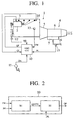
- a high pressure fuel is injected to be supplied from a distribution type electronic control fuel injection pump 2 to respective cylinders of a Diesel engine 1 by fuel injection nozzles 3 provided to the respective cylinders.
- An automatic transmission 4 is provided to an output side of the Diesel engine 1.
- the automatic transmission 4 has a hydraulic torque converter 5 intervening on the output side of the engine 1, a gear type speed change mechanism 6 connected via the hydraulic torque converter 5, and a hydraulic actuator 7 for coupling and releasing various speed change elements in the gear type speed change mechanism 6.
- an oil pump which is driven by the engine 1 is used for obtaining a line pressure which is a hydraulic oil pressure of the hydraulic torque converter 5 and the hydraulic actuator 7, but it is not shown here. Elements related to the oil pump are not shown as well.
- Signals representing various information are inputted from various sensors to an engine control unit 10.
- an accelerator opening sensor 11 for detecting an opening OA of an accelerator pedal, a crank angle sensor 12 for detecting an engine speed NE of the engine 1, a water temperature sensor 13 for detecting a cooling water temperature TW of the engine 1, and a nozzle lift sensor 14 for detecting an actual fuel injection quantity QI which means an actual quantity of a fuel injection are provided.
- a line pressure sensor 15 for detecting a line pressure PL of the automatic transmission 4 is disposed to a piping 16 communicated with the oil pump, not shown, and its signal is inputted into the engine control unit 10.
- the engine control unit 10 calculates a fuel injection quantity QF based on the signals representing various information from the respective sensors so as to control the operation of the fuel injection pump 2.
- the respective signals inputted from the respective sensors into the engine control unit 10 are represented by attaching symbols such as OA, NE or the like corresponding to the information obtained by the respective sensors.
- the signal outputted from the engine control unit 10 into the fuel injection pump 2 is represented by a symbol QF corresponding to the fuel injection quantity which was calculated by the engine control unit 10.
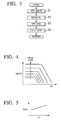
- the engine control unit 10 has a starting fuel injection quantity set block B1 into which a cooling water temperature TW of the engine 1 and an engine speed NE of the engine 1 are inputted, and a starting fuel injection quantity correction block B2 into which a line pressure PL of the automatic transmission 4 is inputted and which corrects a starting fuel injection quantity reference value QFST0 set by the starting fuel injection quantity set block B1.
- the engine control unit 10 executes a process for controlling the fuel injection quantity as shown in FIG. 3 when the engine 1 is started. Such a process is executed for a desired time, for example, three minutes, at predetermined intervals, for example, per one rotation of the engine 1, from the time when an ignition key is turned on.
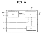
- step 1 (S1) a cooling water temperature TWST at the time of starting the engine 1 and an engine speed NE of the engine 1 are read, and a starting fuel injection quantity reference value QFST0 is set according to the starting cooling water temperature TWST and the engine speed NE by referring to a map previously set and shown in FIG. 4.
- step 1 (S1) is executed by the starting fuel injection quantity set block B1.
- the map used at step 1 (S1) is stored in a memory, not shown, in the engine control unit 10.
- the map has a following property, that is, as the cooling water temperature TWST at the time of starting the engine 1 becomes lower, the starting fuel injection quantity reference value QFST0 increases, and in the meanwhile, even if the cooling water temperature TWST is constant, when the engine speed NE of the engine 1 becomes larger beyond a predetermined value, the starting fuel injection quantity reference value QFST0 decreases from a constant value.
- the property of the map is not limited to this aspect, and it can be set in accordance with actual requirements by the engine 1 or the like.
- the cooling water temperature TWST at the time of starting the engine 1 and the engine speed NE of the engine 1, both of which are read in every time when the starting fuel injection quantity reference value QFST0 is set, are used.
- a line pressure PL is read in based on the signal from the line pressure sensor 15 at step 2 (S2).
- a correction coefficient HOS is set at step 3 (S3) from the actual line pressure PL by referring to a table shown in FIG. 5 where the correction coefficient HOS is previously set according to the line pressure PL.
- the starting fuel injection quantity QFST is corrected to be increased and is optimized for a friction of the automatic transmission 4.
- the processes at steps 2 (S2) through 4 (S4) are executed by the starting fuel injection quantity correction block B2.
- the starting fuel injection quantity at the time of starting the Diesel engine 1 can be optimized for the friction of the automatic transmission, and therefore, white smoke and black smoke can be reduced effectively and the fuel consumption can be reduced effectively.
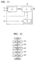
- the engine control unit 10 of the present embodiment has the starting fuel injection quantity set block B1 into which the cooling water temperature TW of the engine 1 and the engine speed NE of the engine 1 are inputted, the starting fuel injection quantity correction block B2 into which the line pressure PL of the automatic transmission 4 is inputted and which corrects the starting fuel injection quantity reference value QFST0 set by the starting fuel injection quantity set block B1, and also a correction quantity variable block B3 which discriminates a fuel property from an inputted actual fuel injection quantity QI and transmits fuel property information F to the starting fuel injection quantity correction block B2 so as to vary its correction quantity HOS used in the starting fuel injection quantity correction block B2.
- the present embodiment is different from the first embodiment in that the correction quantity variable block B3 is further provided, and the other parts of constitution are essentially the same.
- the engine control unit 10 executes a process for controlling a fuel injection quantity shown in FIG. 7 when the engine 1 is started similarly to the first embodiment.
- the starting fuel injection quantity reference value QFST0 is set at step 11 (S11).
- the line pressure PL is read at step 12 (S12).
- step 13 (S13) the fuel property, more concretely, its viscosity is discriminated at step 13 (S13). More concretely, at step 13 (S13), in the case where the viscosity of the fuel is low, a leakage flow rate of the fuel becomes high, and thus the actual fuel injection quantity QI is reduced with respect to the instructed fuel injection quantity. Therefore, a discrimination is made as to whether two types of the viscosity, namely, high viscosity (for example, JIS No. 2 light oil) and low viscosity (for example, JIS special No. 3 light oil) based on the signal of the nozzle lift sensor 14 representing the actual fuel injection quantity QI and transmits the fuel property information F to the starting fuel injection quantity correction block B2. This process is executed by the correction quantity variable block B3.
- high viscosity for example, JIS No. 2 light oil
- low viscosity for example, JIS special No. 3 light oil
- step 14 a table as shown in FIG. 8 where the correction coefficient HOS is previously determined according to the line pressure PL per the fuel property is referred to, so that the correction coefficient HOS is set according to the fuel property in the fuel property information F.
- the correction coefficient HOS when the viscosity is low, the correction coefficient HOS is set so that an increase rate of the fuel injection quantity becomes large based on a characteristic indicated by a solid line in FIG. 8, and when the viscosity is high, the correction coefficient HOS is set so that the increase rate of the fuel injection quantity becomes small based on a characteristic of a dotted line in FIG. 8.
- the table is stored in the memory, not shown, in the engine control unit 10.
- step 11 is executed by the starting fuel injection quantity set block B1
- steps 12 are executed by the processes at steps 12 (S12), step 14 (S14) and step 15 (S15) are executed by the starting fuel injection quantity correction block B2
- the process at step 13 (S13) is executed by the correction quantity variable block B3.
- the fuel property is discriminated and the correction quantity of the starting fuel injection quantity is varied according to the fuel property, more concretely, when the viscosity of the fuel is high, the increase correction quantity is set to be small, and when the viscosity of the fuel is low, the increase correction quantity is set to be large so that the optimized correction quantity is used. Therefore, by taking into account the fuel property, the fuel injection quantity at the time of starting the Diesel engine 1 can be optimized further than the first embodiment, and thus white smoke and black smoke can be reduced effectively and the fuel consumption can be reduced effectively.
- the engine control unit 10 has the starting fuel injection quantity set block B1 into which the cooling water temperature TW of the engine 1 and the engine speed NE of the engine 1 are inputted, the starting fuel injection quantity correction block B2 into which the line pressure PL of the automatic transmission 4 is inputted and which corrects the starting fuel injection quantity reference value QFST0 set by the starting fuel injection quantity set block B1, and also a correction prohibition block B4 into which the actual fuel injection quantity QI is inputted and which discriminates the fuel property from the inputted actual fuel injection quantity QI and transmits correction prohibition information I according to the discriminated fuel property to the starting fuel injection quantity correction block B2 and prohibits the correction if applicable.
- the present embodiment is different from the first embodiment in that the correction prohibition block B4 is provided, and the other parts of the structure are essentially the same. Moreover, instead of the correction quantity variable block B3 of the second embodiment, the correction prohibition block B4 is provided.
- the engine control unit 10 executes a process for controlling a fuel injection quantity shown in FIG. 10 when the engine 1 is started similarly to the first embodiment.
- the starting fuel injection quantity set block B1 sets the starting fuel injection quantity reference value QFST0 at step 21 (S21).
- the correction prohibition block B4 discriminates the fuel property, more concretely the viscosity of the fuel in a similar manner in the correction quantity variable block B3 at step 13 (S13) in the second embodiment.
- the correction prohibition block B4 transmits correction instruction information I regarding an instruction in order to correct the starting fuel injection quantity reference value QFST0, more specifically information representing the correction, to the starting fuel injection quantity correction block B2, and the process goes to step 24 (S24) and step 25 (S25).
- the correction prohibition block B4 transmits the correction instruction information I regarding an instruction to correct the starting fuel injection quantity reference value QFST0, more specifically information representing an instruction in order to prohibit the correction, to the starting fuel injection quantity correction block B2, and the process goes to step 26 (S26). This is because in the case where viscosity of the fuel is high, since the leakage flow rate is low, the increase quantity correction is not required.
- the starting fuel injection quantity correction block B2 executes a process in the case where the viscosity of the fuel is low, namely, corrects the starting fuel injection quantity reference value QFST0. More concretely, the starting fuel injection quantity correction block B2 reads the line pressure PL at step 24 (S24) similarly to the first embodiment, and refers to a table similarly to the first embodiment so as to set the correction coefficient HOS according to the line pressure PL at step 25 (S25).
- the starting fuel injection quantity correction block B2 executes a process in the case where the viscosity of the fuel is high, namely, does execute a process so as not to execute the correction according to the prohibition from the correction of the starting fuel injection quantity reference value QFST0 by the correction prohibition block B4. More concretely, it sets the correction coefficient HOS to 1.
- step 27 the starting fuel injection quantity correction block B2 obtains a final starting fuel injection quantity reference value QFST similarly to the first embodiment.
- the fuel property is discriminated and the correction of the starting fuel injection quantity is prohibited according to the fuel property, more concretely, when the viscosity of the fuel is high, the increase quantity correction is prohibited, and when the viscosity of the fuel is low, the increase quantity correction is executed. Therefore, the necessity of the correction is discriminated by taking into account the fuel property, and in the case where the necessity of the correction is low, the correction is omitted and in the case where the necessity of the correction is high, the correction is executed securely.
- the fuel injection quantity at the time of starting the Diesel engine 1 can be optimized more efficiently than the first embodiment, and thus white smoke and black smoke can be reduced effectively and the fuel consumption can be reduced effectively.
- the engine control unit 10 of the present embodiment has the starting fuel injection quantity set block B1 into which the cooling water temperature TW of the engine 1 and the engine speed NE of the engine 1 are inputted, the starting fuel injection quantity correction block B2 into which the line pressure PL of the automatic transmission 4 is inputted and which corrects the starting fuel injection quantity reference value QFST0 set by the starting fuel injection quantity set block B1, and a correction quantity variable block B5 into which the cooling water temperature TW of the engine 1 is inputted and which transmits temperature information T representing that the cooling water temperature TW is high or low to the starting fuel injection quantity correction block B2 so as to vary the correction quantity HOS.
- the present embodiment is different from the first embodiment in that the correction quantity variable block B5 is provided, and the other elements of the structure are essentially the same. Moreover, the correction quantity variable block B5 is different from the correction quantity variable block B3 of the second embodiment in that it varies the correction quantity HOS according to high or low of the cooling water temperature TW.
- the engine control unit 10 executes a process for controlling a fuel injection quantity shown in FIG. 12 when the engine 1 is started similarly to the first embodiment.
- the starting fuel injection quantity reference value QFST0 is set at step 31 (S31).
- the line pressure PL is read at step 32 (S32).
- step 33 a discrimination is made at step 33 (S33) as to whether the cooling water temperature TWST at the time of starting the engine 1 is high or low, since the friction of the automatic transmission 4 is small when the cooling water temperature TWST at the time of starting the engine 1 is high.
- the cooling water temperature is discriminated based on a signal from the water temperature sensor 13 representing the cooling water temperature TW of the engine 1. In the case where the cooling water temperature TWST at the time of starting the engine 1 is high, for example, at the time of hot-restarting, that is, when the cooling water temperature TW is not less than 90°C, for example, it is discriminated as a high temperature, and when less than 90°C, discriminated as a low temperature.
- temperature discrimination information T is transmitted to the starting fuel injection quantity correction block B2. This process is executed by the correction quantity variable block B5.
- the cooling water temperature TWST at the time of starting the engine 1, which is read in every time when such a discrimination at step 33 (S33) is executed, is used.
- step 34 (S34) a table where the correction coefficient HOS is previously determined according to the line pressure PL per the cooling water temperature TWST at the time of starting the engine 1 is referred to, so that the correction coefficient HOS is set according to high or low temperature in the temperature information T. More specifically, the table used at step 34 (S34) is similar to that shown in FIG. 8, and in the case where the starting cooling water temperature TWST is low, the correction coefficient HOS is set so that the increase quantity rate becomes large based on a characteristic represented by a solid line in FIG.8. On the contrary, in the case where the starting cooling water temperature TWST is high, the correction coefficient HOS is set so that the increase quantity rate becomes small based on a characteristic represented by a dotted line in FIG.8.
- step S31 is executed by the starting fuel injection quantity set block B1
- the processes at steps 32 (S32), 34 (S34) and 35 (S35) are executed by the starting fuel injection quantity correction block B2
- the process at step 33 (S33) is executed by the correction quantity variable block B5.
- the discrimination is made as to whether the cooling water temperature of the engine is high or low, and the correction quantity of the starting fuel injection quantity is varied according to the cooling water temperature, more concretely, when the cooling water temperature is high, the increase correction quantity is set to be small, and when the cooling water temperature is low, the increase correction quantity is set to be large so that the optimized correction quantity is used. Therefore, the cooling water temperature of the engine is taken into account so that the fuel injection quantity at the time of starting the Diesel engine 1 can be optimized more efficiently than the first embodiment, and thus white smoke and black smoke can be reduced effectively and the fuel consumption can be reduced effectively.
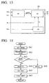
- the engine control unit 10 of the present embodiment has the starting fuel injection quantity set block B1 into which the cooling water temperature TW of the engine 1 and the engine speed NE of the engine 1 are inputted, the starting fuel injection quantity correction block B2 into which the line pressure PL of the automatic transmission 4 is inputted and which corrects the starting fuel injection quantity reference value QFST0 set by the starting fuel injection quantity set block B1, and a correction prohibition block B6 into which the cooling water temperature TW of the engine 1 is inputted and which discriminates as to whether the cooling water temperature TW is high or low and transmits correction prohibition information IT corresponding to the discriminated high or low cooling water temperature TW to the starting fuel injection quantity correction block B2 so as to prohibit the correction if applicable.
- the present embodiment is different from the first embodiment in that the correction prohibition block B6 is provided, and the other elements of the structure are essentially the same. Moreover, the correction prohibition block B6 is different from the correction prohibition block B4 of the third embodiment in that it prohibits the correction according to the high or low cooling water temperature TW.
- the engine control unit 10 executes a process shown in FIG. 14 for controlling a fuel injection quantity when the engine 1 is started similarly to the first embodiment.
- the starting fuel injection quantity set block B1 sets the starting fuel injection quantity reference value QFST0 similarly to the first embodiment.
- the correction prohibition block B6 discriminates as to whether the cooling water temperature TWST at the time of starting the engine 1 is high or low in the similar manner to the process at step 33 (S33) executed by the correction quantity variable block B5 in the fourth embodiment.
- the cooling water temperature TWST at the time of starting the engine 1, which is read in every time when such a discrimination at step 42 (S42) is executed, is used.
- the correction prohibition block B6 transmits the correction instruction information IT regarding an instruction to correct the starting fuel injection quantity reference value QFST0, more specifically, information representing an instruction of the correction, to the starting fuel injection quantity correction block B2, and the process proceeds to steps 44 (S44) and 45 (S45).
- the correction prohibition block B6 transmits the correction instruction information IT regarding correction of the starting fuel injection quantity reference value QFST0, more concretely the information representing the instruction to prohibit the correction, to the starting fuel injection quantity correction block B2, and the process proceeds to step 46 (S46). This is because in the case where the cooling water temperature is high, since the friction of the automatic transmission 4 is small, the increase quantity correction is not required.
- the starting fuel injection quantity correction block B2 executes a process in the case where the cooling water temperature TWST at the time of starting the engine 1 is low, namely, corrects the starting fuel injection quantity reference value QFST0. More concretely, the line pressure PL is read at step 44 (S44) similarly to the first embodiment, and the table is referred to so that the correction coefficient HOS is set according to the line pressure PL at step 45 (S45) similarly to the first embodiment.
- the starting fuel injection quantity correction block B2 executes the process in the case where the cooling water temperature TWST at the time of starting the engine 1, namely, does not execute the correction according to the prohibition from the correction of the starting fuel injection quantity reference value QFST0. More concretely, the correction coefficient HOS is set to 1.
- the process goes from steps 45 (S45) and 46 (S46) to step 47 (S47) so that the starting fuel injection quantity correction block B2 obtains the final starting fuel injection quantity reference value QFST similarly to the first embodiment.
- the discrimination is made as to whether the cooling water temperature of the engine is high or low and the correction of the starting fuel injection quantity is prohibited according to the high or low cooling water temperature, more concretely, when the cooling water temperature is high, the increase quantity correction is prohibited, and when the cooling water temperature is low, the increase quantity is corrected. Therefore, the necessity of the correction is discriminated by taking into account the high or low cooling water temperature of the engine, and when the necessity of the correction is low, the correction is omitted. When the necessity of the correction is high, the correction is executed securely so that the fuel injection quantity at the time of starting the Diesel engine 1 is optimized more efficiently than the first embodiment, and white smoke and black smoke can be reduced effectively and the fuel consumption can be reduced effectively.
Landscapes
- Engineering & Computer Science (AREA)
- Chemical & Material Sciences (AREA)
- Combustion & Propulsion (AREA)
- Mechanical Engineering (AREA)
- General Engineering & Computer Science (AREA)
- Electrical Control Of Air Or Fuel Supplied To Internal-Combustion Engine (AREA)
- Control Of Vehicle Engines Or Engines For Specific Uses (AREA)
Applications Claiming Priority (2)
| Application Number | Priority Date | Filing Date | Title |
|---|---|---|---|
| JP10190447A JP2000018058A (ja) | 1998-07-06 | 1998-07-06 | ディーゼルエンジンの始動時噴射量制御装置 |
| JP19044798 | 1998-07-06 |
Publications (2)
| Publication Number | Publication Date |
|---|---|
| EP0971114A2 true EP0971114A2 (de) | 2000-01-12 |
| EP0971114A3 EP0971114A3 (de) | 2002-05-02 |
Family
ID=16258292
Family Applications (1)
| Application Number | Title | Priority Date | Filing Date |
|---|---|---|---|
| EP99112856A Withdrawn EP0971114A3 (de) | 1998-07-06 | 1999-07-02 | Apparat und Verfahren zür Steuerung der Kraftstoffeinspritzmenge beim Starten eines Dieselmotors |
Country Status (3)
| Country | Link |
|---|---|
| US (1) | US6145486A (de) |
| EP (1) | EP0971114A3 (de) |
| JP (1) | JP2000018058A (de) |
Cited By (1)
| Publication number | Priority date | Publication date | Assignee | Title |
|---|---|---|---|---|
| CN103161594A (zh) * | 2013-03-01 | 2013-06-19 | 无锡威孚高科技集团股份有限公司 | 柴油机电控蓄压分配式共轨系统的油量管理控制系统及方法 |
Families Citing this family (5)
| Publication number | Priority date | Publication date | Assignee | Title |
|---|---|---|---|---|
| JP3715938B2 (ja) * | 2002-04-01 | 2005-11-16 | 株式会社東海理化電機製作所 | エンジン始動・停止制御システム |
| US7481200B2 (en) * | 2002-07-12 | 2009-01-27 | Cummins Engine Company, Inc. | Start-up control of internal combustion engines |
| DE102006048227B4 (de) * | 2006-10-11 | 2008-08-28 | Siemens Ag | Verfahren und Vorrichtung zur Ermittlung einer Betriebscharakteristik eines Einspritzsystems sowie ein entsprechend ausgerüsteter Verbrennungsmotor |
| WO2008051121A1 (en) * | 2006-10-26 | 2008-05-02 | Volvo Lastvagnar Ab | Internal combustion engine for use with a pressurized low viscosity fuel |
| JP4932022B2 (ja) * | 2010-09-27 | 2012-05-16 | 三菱電機株式会社 | アイドルストップ車のエンジン始動制御装置 |
Citations (2)
| Publication number | Priority date | Publication date | Assignee | Title |
|---|---|---|---|---|
| JPS629054A (ja) | 1985-07-04 | 1987-01-17 | Japan Electronic Control Syst Co Ltd | 自動車用オ−トマチツクトランスミツシヨンのライン圧制御装置 |
| JPH10190447A (ja) | 1996-12-16 | 1998-07-21 | Internatl Business Mach Corp <Ibm> | 電荷共有を減少させる回路 |
Family Cites Families (6)
| Publication number | Priority date | Publication date | Assignee | Title |
|---|---|---|---|---|
| JPS55135257A (en) * | 1979-04-05 | 1980-10-21 | Nissan Motor Co Ltd | Line pressure controller for automatic speed change gear |
| JPS56124636A (en) * | 1980-03-05 | 1981-09-30 | Hitachi Ltd | Controlling method of start of engine at low temperature |
| JP3340202B2 (ja) * | 1993-08-13 | 2002-11-05 | 株式会社小松製作所 | ディーゼルエンジンの始動制御方法 |
| JP3412375B2 (ja) * | 1995-03-27 | 2003-06-03 | 日産自動車株式会社 | ディーゼル機関の始動制御装置 |
| DE19540061C1 (de) * | 1995-10-27 | 1996-10-02 | Daimler Benz Ag | Verfahren und Vorrichtung zur Steuerung eines Kraftfahrzeug-Dieselmotors |
| JP3223802B2 (ja) * | 1996-08-09 | 2001-10-29 | 三菱自動車工業株式会社 | 内燃機関の燃料制御装置 |
-
1998
- 1998-07-06 JP JP10190447A patent/JP2000018058A/ja active Pending
-
1999
- 1999-07-02 EP EP99112856A patent/EP0971114A3/de not_active Withdrawn
- 1999-07-06 US US09/348,638 patent/US6145486A/en not_active Expired - Fee Related
Patent Citations (2)
| Publication number | Priority date | Publication date | Assignee | Title |
|---|---|---|---|---|
| JPS629054A (ja) | 1985-07-04 | 1987-01-17 | Japan Electronic Control Syst Co Ltd | 自動車用オ−トマチツクトランスミツシヨンのライン圧制御装置 |
| JPH10190447A (ja) | 1996-12-16 | 1998-07-21 | Internatl Business Mach Corp <Ibm> | 電荷共有を減少させる回路 |
Cited By (2)
| Publication number | Priority date | Publication date | Assignee | Title |
|---|---|---|---|---|
| CN103161594A (zh) * | 2013-03-01 | 2013-06-19 | 无锡威孚高科技集团股份有限公司 | 柴油机电控蓄压分配式共轨系统的油量管理控制系统及方法 |
| CN103161594B (zh) * | 2013-03-01 | 2015-05-27 | 无锡威孚高科技集团股份有限公司 | 柴油机电控蓄压分配式共轨系统的油量管理控制系统及方法 |
Also Published As
| Publication number | Publication date |
|---|---|
| US6145486A (en) | 2000-11-14 |
| EP0971114A3 (de) | 2002-05-02 |
| JP2000018058A (ja) | 2000-01-18 |
Similar Documents
| Publication | Publication Date | Title |
|---|---|---|
| EP2169252B1 (de) | Kupplungssteuerungsvorrichtung für Fahrzeuge | |
| US8788165B2 (en) | Abnormal state diagnosis method for oil temperature sensor of automatic transmission | |
| US6584834B1 (en) | Method for detecting combustion misses | |
| US6145486A (en) | Apparatus for controlling fuel injection quantity at the time of starting diesel engine and method | |
| EP1612391B1 (de) | Vorrichtung und Verfahren zur Regelung der Abgasrückführung einer Brennkraftmaschine | |
| US6799108B2 (en) | Control system and method for maintaining a constant engine idle speed of an automatic transmission-equipped vehicle | |
| US6832150B2 (en) | Method and apparatus for controlling diesel engine | |
| EP0937878B1 (de) | Elektronisches Kraftstoffeinspritzgerät für einen Dieselmotor | |
| US6231478B1 (en) | Method and system for controlling engine idle revolution number | |
| EP0962640B1 (de) | Steuerapparat für die Steuerung eines Verbrennungsmotors | |
| US6032645A (en) | Electronic fuel injection apparatus for diesel engine | |
| US5661974A (en) | Control system with function of protecting catalytic converter for internal combustion engines for vehicles | |
| KR101991137B1 (ko) | 내연기관의 손실 토크의 적응을 위한 방법 및 장치 | |
| US5960773A (en) | Engine control apparatus | |
| JP2861507B2 (ja) | 内燃機関のアイドル回転数制御装置 | |
| JPH05312076A (ja) | アイドル回転数制御装置 | |
| KR100394656B1 (ko) | 디젤 엔진의 연료 제어방법 및 시스템 | |
| KR100360799B1 (ko) | 자동차용 인젝터의 노화를 보상하는 인젝터맵 적용방법 | |
| JPH01150053A (ja) | 自動変速機付エンジンの制御装置 | |
| US20250242793A1 (en) | Stabilization factors and approaches in real-time vehicle powertrain mode optimization | |
| KR100405711B1 (ko) | 커먼레일 디젤 엔진의 연료누유 감지방법 | |
| JP3183425B2 (ja) | 車両用自動変速機付内燃機関の制御装置 | |
| JP2002174137A (ja) | エンジン油温推定方法 | |
| JPH04213057A (ja) | 燃料性状検出装置 | |
| KR20040050302A (ko) | 차량의 연료 공급 보상 제어장치 및 방법 |
Legal Events
| Date | Code | Title | Description |
|---|---|---|---|
| PUAI | Public reference made under article 153(3) epc to a published international application that has entered the european phase |
Free format text: ORIGINAL CODE: 0009012 |
|
| 17P | Request for examination filed |
Effective date: 19990702 |
|
| AK | Designated contracting states |
Kind code of ref document: A2 Designated state(s): AT BE CH CY DE DK ES FI FR GB GR IE IT LI LU MC NL PT SE Kind code of ref document: A2 Designated state(s): DE FR GB |
|
| AX | Request for extension of the european patent |
Free format text: AL;LT;LV;MK;RO;SI |
|
| PUAL | Search report despatched |
Free format text: ORIGINAL CODE: 0009013 |
|
| AK | Designated contracting states |
Kind code of ref document: A3 Designated state(s): AT BE CH CY DE DK ES FI FR GB GR IE IT LI LU MC NL PT SE |
|
| AX | Request for extension of the european patent |
Free format text: AL;LT;LV;MK;RO;SI |
|
| AKX | Designation fees paid |
Free format text: DE FR GB |
|
| STAA | Information on the status of an ep patent application or granted ep patent |
Free format text: STATUS: THE APPLICATION HAS BEEN WITHDRAWN |
|
| 18W | Application withdrawn |
Effective date: 20041117 |