EP0971271A1 - Apparat für die Herstellung von Bildern - Google Patents
Apparat für die Herstellung von Bildern Download PDFInfo
- Publication number
- EP0971271A1 EP0971271A1 EP99113332A EP99113332A EP0971271A1 EP 0971271 A1 EP0971271 A1 EP 0971271A1 EP 99113332 A EP99113332 A EP 99113332A EP 99113332 A EP99113332 A EP 99113332A EP 0971271 A1 EP0971271 A1 EP 0971271A1
- Authority
- EP
- European Patent Office
- Prior art keywords
- image
- photosensitive member
- image forming
- forming apparatus
- carrying member
- Prior art date
- Legal status (The legal status is an assumption and is not a legal conclusion. Google has not performed a legal analysis and makes no representation as to the accuracy of the status listed.)
- Withdrawn
Links
Images


Classifications
-
- G—PHYSICS
- G03—PHOTOGRAPHY; CINEMATOGRAPHY; ANALOGOUS TECHNIQUES USING WAVES OTHER THAN OPTICAL WAVES; ELECTROGRAPHY; HOLOGRAPHY
- G03G—ELECTROGRAPHY; ELECTROPHOTOGRAPHY; MAGNETOGRAPHY
- G03G5/00—Recording-members for original recording by exposure, e.g. to light, to heat or to electrons; Manufacture thereof; Selection of materials therefor
- G03G5/02—Charge-receiving layers
- G03G5/04—Photoconductive layers; Charge-generation layers or charge-transporting layers; Additives therefor; Binders therefor
- G03G5/08—Photoconductive layers; Charge-generation layers or charge-transporting layers; Additives therefor; Binders therefor characterised by the photoconductive material being inorganic
- G03G5/082—Photoconductive layers; Charge-generation layers or charge-transporting layers; Additives therefor; Binders therefor characterised by the photoconductive material being inorganic and not being incorporated in a bonding material, e.g. vacuum deposited
- G03G5/08214—Silicon-based
- G03G5/08221—Silicon-based comprising one or two silicon based layers
Definitions
- the present invention relates to an image forming apparatus and, more particularly to, an image forming apparatus that has amorphous silicon photosensitive members.
- amorphous silicon photosensitive members have largely been employed gradually as being indispensable in particular in the high-speed machines, which require high reliabilities, because of their large hardness (1000 kg/m 2 or higher of JIS-standard Vickers hardness), high durability, high heat resistance, and excellent ecological stability.
- a magnet roller should be arranged on the upstream side of the cleaning blade to make a magnetic brush of some of toner collected into the cleaning apparatus, which brush be in turn brought in contact with the surface of the image forming member to re-supply magnetic toner so that the toner particles on the blade side may, by their abrasive action, remove the above-mentioned various kinds of foreign matter by sliding operation.
- Such a method will have a less local unevenness of the abrasive action on the image carrying member surface and a smaller deterioration of that surface than such an approach that a web or rubber roller polish, by sliding, that surface with abrasives.
- an attendant method may be employed that lowers the surrounding humidity even during stand-by operation at night, so as to prevent the resistance of the surface of the image carrying member from decreasing, thus blocking to some extent the deterioration in the picture quality due to the earlier mentioned factors.
- the residual toner on the image carrying member needs to be removed for each process without shifting it onto the transfer material.
- a cleaning blade made of urethane rubber or other elastic materials is used to dust away the above-mentioned residual toner, because it has a simple and compact configuration with lower costs and is excellent in performance of removing toner.
- urethane rubber is generally used for its high hardness, good elasticity, good wear-resistance, high mechanical strength, good oil-resistance, high ozone-resistance etc.
- Possible factors for image smearing include toner, minute paper particles generated from paper used mostly as a transfer material, the resultantly deposited organic substances, and such components as nitric ions given as a result of oxidation of nitrogen in the air at the same time as the generation of various kinds of metal oxides and oxidized compounds generated at the corona discharge with high energy from build-in high tension members, which all attach to the surface of the image carrying member as it is used to form thin films (hereinafter called filming membrane) on the photosensitive member surface, thus absorbing the humidity in the high humidity environments to lower the resistance and prevent the formation of clear electrostatic latent images, which leads to the deterioration of the picture quality.
- filming membrane thin films
- the above-mentioned filming membrane layer has been confirmed to measure in thickness about 30 to 80 ⁇ by an optical method in our experiments. In our experiments of durability test conducted in this case, however, it has been found that the above-mentioned filming membrane initially measured in thickness about 30 to 80 ⁇ and then changed little but as time passes, the image deterioration, which could have initially been eliminated by dry-wiping, water-wiping, or alcohol-wiping, cannot be done so. It has been found that in some cases the drum surface which has undergone the durability test to some extent in such a state cannot sufficiently be freed from image deterioration, unless it is polished with abrasive grains of 0.3 to 2.0 ⁇ m cerium oxide (CeO 2 ) dispersed in alcohol.
- CeO 2 cerium oxide
- An increase in friction is considered to increase the shearing stress of the cleaning blade, that among toner, and that in the vicinity of the drum surface. As a result, this is considered to lead to the chipping of the cleaning blade, the occurrence due to increases in the amount of heat generated by increases in the permanent strain shearing stress and also increases in the fatigue wear due in increases in the intra-drum stress.
- the image forming apparatus has not only been used as a copy machine but also as a printer widely.
- the apparatus has been provided with such application functions as feeding functions and sorting functions, so that its one job can continuously process 4000 sheets or more of paper.
- the ambient temperature is considered to rise up to near 50°C near the photosensitive member and higher at the butting (nipping) part between the cleaning blade and the photosensitive member. Therefore, it is considered that melt-adhesion frequently occurs on the photosensitive member.
- the cleaning blade has been determined in terms of its cleaning latitude by the butting angle against the drum surface, the free length, the thickness, the total pressure, the linear pressure, and the properties of rubber used as the cleaning blade.
- Japanese Patent Application Laid-Open No. 6-274079 describes that in order to eliminate the chipping on the cleaning blade and the cleaning blade fluttering in the low-temperature and low-humidity environments, the peak temperature of tan ⁇ should be at -13°C to -16°C, the impact resilience should be higher, and the Young's modulus should be lower. However, it describes nothing about the impact resilience under the high-temperature region.
- toner melt-adhesion on the drum is different between an amorphous silicon photosensitive member and an organic photosensitive member.
- toner melt-adhesion occurs because minute particles of an external additive such as silica are embedded into the photosensitive member surface to provide nucleuses
- raining-state toner melt-adhesion occurs when there are few- ⁇ m-height protrusions on the photosensitive member surface or even when there are nothing that provide nucleuses.
- an object of the present invention is to largely improve the reliabilities of electrophotographic apparatuses by utilizing their photosensitive member surface not to generate image smearing even without drum heaters and their cleaning blade not to generate melt-adhesion and also to provide such an electrophotographic apparatus that can accommodate an extremely high productivity.
- An another object of the present invention is to provide an image forming apparatus comprising an image forming part which forms toner images on a image carrying member, an image transfer part which transfers onto a transfer material the toner images on the image carrying member, and cleaning means which removes post-transfer residual toner left on the image carrying member after the images are transferred onto the transfer material by the image transfer part, wherein the image carrying member is an amorphous silicon photosensitive member and the photosensitive member has an initial average gradient ⁇ a of 0.0001 to 0.005.
- a still another object of the present invention is to provide an image forming apparatus, wherein the image carrying member has abnormally grown protrusions on its surface having a height of 5.0 ⁇ m or less, wherein the photosensitive member has a wear rate in an actual service condition of 0.01 ⁇ /1000 revolutions to 2.0 ⁇ /1000 revolutions, wherein the cleaning means is an elastic blade which has a modulus of repulsion elasticity of 45 % or less at 45°C and also a temperature dependency of the modulus repulsion elasticity of 0 %/°C to +1 %/°C in a temperature range of 5°C to 60°C and in a range where its properties exhibit rubbery state, wherein the width of abutting (nip width) of the cleaning blade against the drum surface is 5 ⁇ m to 60 ⁇ m, or wherein the toner has an average particle diameter of 6 ⁇ m to 8 ⁇ m and comprises solid wax of 0.2 to 20 parts by weight and magnetic particles of 10 to 200 parts by weight based on a binding resin,
- an image forming apparatus comprising an image forming part which forms toner images on an image carrying member, an image transfer part which transfers the above-mentioned toner images on the above-mentioned image carrying member onto an transfer material, and a cleaning means which removes post-transfer residual toner left on the above-mentioned image carrying member after images are transferred onto the above-mentioned transfer material by the above-mentioned image transfer part, the initial average gradient ⁇ a of the above-mentioned photosensitive member of 0.0001 to 0.005 improves the reliabilities for image smearing without the surface resistance being lowered due to higher humidity.
- the reliabilities can be improved by using a cleaning blade material that has a modulus of repulsion elasticity of as low as 45 % or less at 45°C and its temperature dependency of 0 %/°C to 1 %/°C.
- the causes for toner melt-adhesion on the drum surface is different between an amorphous silicon photosensitive member and an organic photosensitive member.
- minute particles of an external additive such as silica are embedded into the photosensitive member surface to provide nucleuses, thus giving rise to toner melt-adhesion
- raining-state toner melt-adhesion occurs when there are few- ⁇ m-height protrusions on the photosensitive member surface or even when there are nothing which provide nucleuses.
- melt-adhesion In the former case of melt-adhesion, in particular, it was found that no melt-adhesion occurs when the height of the protrusions is 5 ⁇ m or less even with an average particle diameter of 6 ⁇ m. In the latter case of melt-adhesion, it was found that there is correlation between itself and the modulus of repulsion elasticity of the blade material. The modulus of repulsion elasticity at a normal measurement temperature of 23°C is different from that of the actual apparatus in the actual service conditions. As we discussed further, it has found that by reducing the temperature-dependency of the modulus of repulsion elasticity, it is possible to prohibit toner melt-adhesion from occurring against fluctuations due to variations in the ambient temperature and a temperature rise caused by continuous feeding of paper.
- FIG. 1 shows a region of melt-adhesion occurrence against temperature and modulus of repulsion elasticity.
- a member 1 has a higher value of modulus of repulsion elasticity (%) than the simultaneous value of temperature (°C), so that melt-adhesion occurs.
- the cleaning blade rubber material becomes higher in elasticity as the temperature rises.
- the nip width even when the total pressure is increased, the nip width only increases without increasing the surface pressure.
- the nip width is 60 ⁇ m or more, the filming membranes are often stacked from the initial state. This is considered because the cleaning blade does not securely abut the photosensitive member but abuts it loose, i.e. the pressure distribution against the cleaning blade becomes broad.
- the nip width is 10 ⁇ m or less on the other hand, the part component tolerance is critical, so that nips cannot be formed locally, giving rise to insufficient cleaning. If the nip width is 10 to 60 ⁇ m, it is possible to prohibit the formation of filming membranes which give poor images.
- Charge-injection blocking layers and photoconductive layers were stacked on a cylindrical conductive substrate using a plasma CVD apparatus under such conditions as listed in Table 1 and then a surface layer is deposited as thick as 0.6 ⁇ m under such conditions as listed in Table 2, to make a light-receiving member, which serves as an image carrying member.
- FIG. 2 shows an example of a schematic cross-sectional view of a light-receiving member according to the present invention.
- the a-Si light-receiving member shown in FIG. 2 comprises a photosensitive layer 402 having on it a photoconductive layer 403 made of an amorphous material containing at least silicon atoms stacked on a conductive substrate 401 made of aluminum etc. and, on top of that, a surface layer 404 made of a-C:H film or a-SiC:H film containing carbon and hydrogen atoms, although in the figure shows an example of providing a charge-injection blocking layer between the conductive substrate 401 and the photoconductive layer 403.
- a light-receiving member may be deposited by a well known plasma CVD method, it is preferred to supply a high-frequency power of 1 MHz to 450 MHz from a high-frequency power supply to produce high-frequency glow discharge, thus improving the performance of cleaning the surface layer.
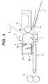
- FIGS. 3 and 4 the general configuration of an electrophotographic apparatus is described as an example of an image forming apparatus related to the present invention.
- FIG. 3 is a cross-sectional view of the basic configuration of an electrophotographic apparatus, in which reference numeral 1 indicates a drum shaped amorphous silicon photosensitive member which is rotated and driven at a prescribed speed in the direction of illustrated arrow R1 and around which are arranged a pre-exposure apparatus 2, a primary charger 3, a developing apparatus 5, a transfer separating charger 7, and a cleaning apparatus 9.
- the cleaning blade 9a of the above-mentioned cleaning apparatus 9 is made of urethane rubber having a thickness of 2 mm.
- the primary charger 3, a developing sleeve 5a and the transfer separating charger 7 are connected with a high-voltage power supply (not shown). Also, the photosensitive member 1 and the developing sleeve 5a have each a drive motor (not shown) and rotated and driven independently of each other thereby.
- a transfer material P is fed onto a resist roller 10 by a carrying system (not shown) and then sent at appropriate timing by the resist roller 10 to a transfer nip part between the photosensitive drum 1 and the transfer separating charger 7, where the toner image on the photosensitive member 1 is transferred and then separated from the photosensitive member 1 by the action of the transfer separating charger 7.
- the transfer material P thus separated from the photosensitive member 1 is sent by the carrying apparatus 11 to a fixing apparatus 12 to fix the transfer material P with the toner image transferred.
- the maximum image width for an electrophotographic copy machine related to the present embodiment is about 290 mm, the width of a A4-size paper, and the drum's peripheral speed is 300 mm/sec.
- the photosensitive member 1 is made of an about 3 mm thick aluminum cylinder, on which a 30 ⁇ m thick amorphous silicon photosensitive layer is formed by the glow discharge.
- SiC:H As the surface layer of the photosensitive member , SiC:H was stacked as thick as 800 ⁇ .
- the developing apparatus 5 has on its surface a developing sleeve 5a on which a coating layer containing a mixture of phenol resin, graphite, and carbon is formed and in itself, toner t which serves as a developer.
- the developing sleeve 5a is driven at a relative speed 150 % in a forward direction with the photosensitive member 1, with the gap therebetween being set at 230 ⁇ m.
- a magnetic blade is used, with the gap therebetween set at 280 ⁇ m, in which state, a square wave having peak-to-peak voltage of 1400 V, a frequency of 2700 Hz, and a duty ratio of 35 % to which a direct current is superimposed is applied to the developing sleeve 5a.
- a cleaning blade 4 which is abutted against the surface of the photosensitive member 1.
- FIG. 4 is a schematic cross-sectional view of the cleaner part, wherein a cleaning blade 9a is an elastic blade mainly made of urethane having a hardness of 70 degrees (Hs), a modulus of repulsion elasticity of 15 % (25 % at 40°C), 300 % modulus 200 (kg/cm 2 ), all based on the JIS Standards, and is arranged on the photosensitive member 1 with an abutting angle of 24 degrees, an abutting pressure of 10 g/cm 2 , and a surface pressure of 150 g/mm 2 .
- the cleaning blade has a free length of 3 mm.
- an elongated magnet roller 22 is formed perpendicular to the paper of FIG. 3 with a prescribed gap between itself and the photosensitive member 1.
- a separating claw 29 is arranged on the upstream side of the pre-exposure light of the cleaner.
- the magnetic roller 22 rotates at a peripheral speed of relative speed 10 % in a forward direction with the rotation direction of the photosensitive member 1.
- the pre-exposure light 2 is emitted from a light emitting diode mainly of a peak wavelength of 660 nm and has a half-band width of about 25 nm, which is 1/2 of the peak wavelength, and an exposure amount of 20 ⁇ J/cm 2 .
- a distance between the pre-exposure light 2 and the primary charger 3 is about 50 mm/sec.
- the magnetic roller 22 rotates at a peripheral speed of relative speed 180 % in a backward direction against the rotation direction of the photosensitive member 1.
- the magnetic roller 22 is arranged against the photosensitive member 1 with a gap of 1.0 mm therebetween.
- a restricting roller 23 is arranged against the magnetic roller 22 with a gap of 1.8 mm therebetween and rotates at a relative speed 180 % in a backward direction against the magnetic roller 22.
- the pre-exposure light 3 is emitted from an emitting diode (made of GaAlAs) mainly of a 660 nm peak wavelength and has a half-band width of about 25 nm, which is half the peak wavelength, and an exposure amount of 10 ⁇ J/cm 2 .
- a distance between the pre-exposure light 2 and the primary charger 3 is about 50 mm/sec.
- octagonal magnetic powder having an average particle diameter of 0.18 ⁇ m.
- One-component magnetic toner was used that the positive charging average particle diameter is 6.5 ⁇ m, the main binder is styrene-acryl copolymer, a magnetic substance of 100 parts by weight and a silica, inorganic powder, of 0.5 part by weight as an external additive were used, and the glass transition point is about 60°C and, the charge quantity on its developing sleeve 5a is +3 to +12 ( ⁇ C/g) and the coating quantity is 0.6 to 1.3 mg/cm 2 .
- the photosensitive member showed no melt-adhesion, partial filming membranes, no frictional damages etc. on images.
- the wear was 0.4 ⁇ /1000 revolutions.
- the average gradient ⁇ a of the photosensitive member after the 3-million-sheet test was 0.0001.
- the average gradient ⁇ a of the photosensitive member turned out to be 0.0005 after it underwent heating in 5 % of an aqueous solution of sodium peroxodisulfate (70 to 80°C, 30 minutes), ultra sonic cleaning (about 1 minute) in acetone, and rinsing with ethanol/pure water.
- the average gradient ⁇ a was measured with an atomic force microscope (AFM: made by Digital Instruments, NannoSonic IIIa Dimension 3000/scanning mode, tapping mode/scanning scope: 200 ⁇ m ⁇ 20 ⁇ m, probe: Si-cantilever).
- AFM atomic force microscope
- the average gradient ⁇ a indicates an average gradient of irregular inclined surface at a prescribed length, in short, it corresponds to the average of tangent of a prescribed section.
- a reflection spectroscopy type interferometer (type MCDP2000 from Ohtsuka Densi Co. Ltd.) was also used to measure the film thickness, to find a 10 ⁇ -thick filming layer.
- photosensitive members B, G, and H After the 3-million-sheet durability test, photosensitive members B, G, and H also showed no problems such as image smearing even under the high-temperature, high-humidity environments (32.5°C/85 %). Also, no chipping at the cleaning blade edges was observed. After the 3-million-sheet durability test, the photosensitive member showed no problems such as melt-adhesion, partial filming membrane, frictional damages etc. on images.
- Example 2 The same configuration was used as Example 1, except that a photosensitive member G was used and the cleaning blade was changed as follows.
- Such a cleaning blade was arranged on the photosensitive member 1 that comes in an elastic blade mainly made of urethane and has a hardness of 77 degrees (Hs), a modulus of repulsion elasticity of 10 % at 25°C (20 % even at 40°C), a 300 %-modulus of 250 kg/cm 2 , all based on the JIS Standards, and also an abutting angle of 28 degrees, an abutting pressure of 20 kg/cm 2 , and a surface pressure of 200 g/mm 2 .
- Hs hardness of 77 degrees
- a modulus of repulsion elasticity 10 % at 25°C (20 % even at 40°C
- a 300 %-modulus 250 kg/cm 2
- all abutting angle of 28 degrees an abutting pressure of 20 kg/cm 2
- a surface pressure of 200 g/mm 2 a surface pressure of 200 g/mm 2 .
- Example 1 Almost the same configuration as Example 1 was used in this Example except for some changes, which are described as referring to FIG. 5.
- a urethane-made sponge roller 30 was arranged in place of the magnetic roller 22, a urethane-made sponge roller 30 was arranged.
- the urethane-made sponge roller 30 comprises an urethane sponge mounted as thick as 4.0 mm on a ⁇ 12 core bar, the sponge has a porosity of 0.60.
- the same cleaning blade was used as in Example 1.
- the urethane-made sponge roller is applied onto the photosensitive member 1 with a total pressure of 2.0 kgf and rotates at a peripheral speed of relative speed 25 % in a forward direction with the rotation direction of the photosensitive member 1.
- a photosensitive member D was used with the same configuration as in Example 1.
- the photosensitive member After about 0.5 million sheets of durability test was conducted under the high-temperature, high-humidity environments (32.5°C/85 %), image smearing occurred in some cases. After the one-million-sheet test, the average gradient ⁇ a of the photosensitive member was 0.001. Then, the photosensitive member underwent heating (70 to 80°C, 30 minutes) in 5 % of an aqueous solution of sodium peroxodisulfate (Na 2 S 2 O 8 ) and ultrasonic cleaning in acetone (about 1 minute) and also rinsing with ethanol/pure water, resulting in the average gradient ⁇ a of the itself of 0.004.
- the film thickness was measured with a reflection spectrometry type interferometer (type MCDP2000 from Ohtsuka Densi, Co., Ltd.) before and after cleaning, to make sure of a filming layer thickness of 80 ⁇ . Also, photosensitive members C, E, and F were discussed and, as a result, image smearing was observed respectively after one-, 0.6-, and 1.2-million-sheet durability tests under the high-temperature, high-humidity environments (32.5°C/85 %).
- a reflection spectrometry type interferometer type MCDP2000 from Ohtsuka Densi, Co., Ltd.
- Example 1 The same configuration as Example 1 was used except for the material of the cleaning blade.
- Such a cleaning blade was arranged on the photosensitive member 1 that comes in an elastic blade mainly made of urethane with a hardness of 73 degrees (Hs) and has a modulus of repulsion elasticity of 35 % at 25°C (67 % even at 40°C), a 300% modulus of 150 kg/cm 2 , all based on the JIS Standards, and also has an abutting angle of 24 degrees, an abutting pressure of 10 kg/cm 2 , and a surface pressure of 150 g/mm 2 .
- Hs hardness of 73 degrees
- melt-adhesion occurred in some cases. In addition, once it has occurred, melt-adhesion was lengthened and became numerous.
- Example 3 Almost the same configuration was used as Example 3, except that the sponge roller was rotated at a peripheral speed of relative speed 50 % in a forward direction with the rotation direction of the photosensitive member 1.
- a photosensitive member E was used.
- the film thickness was measured with a reflection spectroscopy type interferometer (type MCDP2000 from Ohtsuka Densi, Co., Ltd.) and came up with a result that the wear was 2.4 ⁇ /1000 revolutions.
- Example 2 The same basic configuration was used as Example 2, except that there are abnormally grown protrusions as high as 8 ⁇ m on the photosensitive member 1. After about 30,000 sheets of paper were fed through, melt-adhesion occurred at the protrusions, while after 0.5 million sheets of paper were fed through, poor cleaning was observed at the protrusions.
Landscapes
- Chemical & Material Sciences (AREA)
- Inorganic Chemistry (AREA)
- Physics & Mathematics (AREA)
- General Physics & Mathematics (AREA)
- Cleaning In Electrography (AREA)
- Discharging, Photosensitive Material Shape In Electrophotography (AREA)
- Photoreceptors In Electrophotography (AREA)
- Developing Agents For Electrophotography (AREA)
Applications Claiming Priority (2)
| Application Number | Priority Date | Filing Date | Title |
|---|---|---|---|
| JP19580798 | 1998-07-10 | ||
| JP19580798A JP2000029232A (ja) | 1998-07-10 | 1998-07-10 | 画像形成装置 |
Publications (1)
| Publication Number | Publication Date |
|---|---|
| EP0971271A1 true EP0971271A1 (de) | 2000-01-12 |
Family
ID=16347318
Family Applications (1)
| Application Number | Title | Priority Date | Filing Date |
|---|---|---|---|
| EP99113332A Withdrawn EP0971271A1 (de) | 1998-07-10 | 1999-07-09 | Apparat für die Herstellung von Bildern |
Country Status (3)
| Country | Link |
|---|---|
| US (1) | US6233417B1 (de) |
| EP (1) | EP0971271A1 (de) |
| JP (1) | JP2000029232A (de) |
Cited By (2)
| Publication number | Priority date | Publication date | Assignee | Title |
|---|---|---|---|---|
| US6586149B2 (en) * | 2000-03-16 | 2003-07-01 | Canon Kabushiki Kaisha | Light-receiving member, image-forming apparatus, and image-forming method |
| EP2310916A4 (de) * | 2008-12-26 | 2013-07-03 | Canon Kk | Bilderzeugungsverfahren |
Families Citing this family (13)
| Publication number | Priority date | Publication date | Assignee | Title |
|---|---|---|---|---|
| US6605405B2 (en) * | 2000-07-26 | 2003-08-12 | Canon Kabushiki Kaisha | Electrophotographic method and electrophotographic apparatus |
| US6722015B2 (en) | 2001-08-11 | 2004-04-20 | General Electric Company | Assembly method for stamped and cupped laminations |
| US6847285B2 (en) * | 2001-08-13 | 2005-01-25 | General Electric Company | Interlock tabs for laminations |
| US7020427B2 (en) * | 2004-07-15 | 2006-03-28 | Xerox Corporation | Carrier pickoff system suitable for customer-replaceable xerographic printer cartridges |
| JP4704080B2 (ja) * | 2005-03-18 | 2011-06-15 | 株式会社リコー | クリーニング装置、プロセスユニット、及び画像形成装置 |
| US7869721B2 (en) * | 2008-07-07 | 2011-01-11 | Xerox Corporation | Apparatus and method for detecting carrier particles in an electrophotographic device |
| WO2010010971A1 (en) * | 2008-07-25 | 2010-01-28 | Canon Kabushiki Kaisha | Image-forming method and image-forming apparatus |
| JP5121785B2 (ja) * | 2008-07-25 | 2013-01-16 | キヤノン株式会社 | 電子写真感光体および電子写真装置 |
| US7962085B2 (en) * | 2009-10-15 | 2011-06-14 | Xerox Corporation | Metal blade cleaning of an amorphous silicon receptor |
| JP5653186B2 (ja) * | 2009-11-25 | 2015-01-14 | キヤノン株式会社 | 電子写真装置 |
| JP5675287B2 (ja) * | 2009-11-26 | 2015-02-25 | キヤノン株式会社 | 電子写真感光体および電子写真装置 |
| JP5675292B2 (ja) * | 2009-11-27 | 2015-02-25 | キヤノン株式会社 | 電子写真感光体および電子写真装置 |
| JP5777419B2 (ja) | 2010-06-28 | 2015-09-09 | キヤノン株式会社 | 電子写真感光体および電子写真装置 |
Citations (3)
| Publication number | Priority date | Publication date | Assignee | Title |
|---|---|---|---|---|
| EP0785475A2 (de) * | 1996-01-19 | 1997-07-23 | Canon Kabushiki Kaisha | Photorezeptorelement, umfassend eine Schutzschicht mit spezifischer Aussenoberfläche, und Verfahren zu dessen Herstellung |
| EP0809153A2 (de) * | 1996-05-23 | 1997-11-26 | Canon Kabushiki Kaisha | Lichtempfangselement |
| EP0825493A2 (de) * | 1996-08-23 | 1998-02-25 | Canon Kabushiki Kaisha | Elektrophotographisches Gerät, Bilderzeugungsverfahren und Verfahren zur Herstellung eines lichtempfindlichen Elementes für die Elektrophotographie |
Family Cites Families (9)
| Publication number | Priority date | Publication date | Assignee | Title |
|---|---|---|---|---|
| JPS5392133A (en) * | 1977-01-25 | 1978-08-12 | Ricoh Co Ltd | Electrophotographic photosensitive material |
| DE3204221A1 (de) * | 1982-02-08 | 1983-08-18 | Hoechst Ag, 6230 Frankfurt | Elektrophotographisches aufzeichnungsverfahren und hierfuer geeignete photoleiterschicht |
| US4650736A (en) * | 1984-02-13 | 1987-03-17 | Canon Kabushiki Kaisha | Light receiving member having photosensitive layer with non-parallel interfaces |
| JPH0711706B2 (ja) * | 1984-07-14 | 1995-02-08 | ミノルタ株式会社 | 電子写真感光体 |
| JPS62106470A (ja) * | 1985-11-02 | 1987-05-16 | Canon Inc | 光受容部材 |
| JPH06274079A (ja) | 1993-03-19 | 1994-09-30 | Fuji Xerox Co Ltd | クリーニングブレード |
| JPH0710488A (ja) | 1993-06-23 | 1995-01-13 | Toyota Autom Loom Works Ltd | フォークリフトのマスト装置 |
| JPH08129266A (ja) | 1993-12-17 | 1996-05-21 | Fuji Xerox Co Ltd | 電子写真感光体 |
| JPH07219245A (ja) * | 1994-02-09 | 1995-08-18 | Kyocera Corp | 電子写真感光体および画像形成方法 |
-
1998
- 1998-07-10 JP JP19580798A patent/JP2000029232A/ja active Pending
-
1999
- 1999-07-08 US US09/349,078 patent/US6233417B1/en not_active Expired - Lifetime
- 1999-07-09 EP EP99113332A patent/EP0971271A1/de not_active Withdrawn
Patent Citations (3)
| Publication number | Priority date | Publication date | Assignee | Title |
|---|---|---|---|---|
| EP0785475A2 (de) * | 1996-01-19 | 1997-07-23 | Canon Kabushiki Kaisha | Photorezeptorelement, umfassend eine Schutzschicht mit spezifischer Aussenoberfläche, und Verfahren zu dessen Herstellung |
| EP0809153A2 (de) * | 1996-05-23 | 1997-11-26 | Canon Kabushiki Kaisha | Lichtempfangselement |
| EP0825493A2 (de) * | 1996-08-23 | 1998-02-25 | Canon Kabushiki Kaisha | Elektrophotographisches Gerät, Bilderzeugungsverfahren und Verfahren zur Herstellung eines lichtempfindlichen Elementes für die Elektrophotographie |
Cited By (4)
| Publication number | Priority date | Publication date | Assignee | Title |
|---|---|---|---|---|
| US6586149B2 (en) * | 2000-03-16 | 2003-07-01 | Canon Kabushiki Kaisha | Light-receiving member, image-forming apparatus, and image-forming method |
| US7060406B2 (en) | 2000-03-16 | 2006-06-13 | Canon Kabushiki Kaisha | Light-receiving member, image-forming apparatus, and image-forming method |
| EP2310916A4 (de) * | 2008-12-26 | 2013-07-03 | Canon Kk | Bilderzeugungsverfahren |
| US8758971B2 (en) | 2008-12-26 | 2014-06-24 | Canon Kabushiki Kaisha | Image-forming method |
Also Published As
| Publication number | Publication date |
|---|---|
| US6233417B1 (en) | 2001-05-15 |
| JP2000029232A (ja) | 2000-01-28 |
Similar Documents
| Publication | Publication Date | Title |
|---|---|---|
| US6233417B1 (en) | Image forming apparatus | |
| JP3507322B2 (ja) | 電子写真装置 | |
| US5459558A (en) | Charging device, image forming apparatus with same and a process unit detachably mountable to the image forming apparatus | |
| US6171742B1 (en) | Photosensitive member to be used for image-forming apparatus and image-forming apparatus comprising such photosensitive member | |
| EP0953882B1 (de) | Electrophotographisches Bildaufzeichnungsverfahren | |
| EP0957413B1 (de) | Reinigungsmethode in einem elektrophotographischen Gerät und elektrophotographisches Verfahren unter Verwendung dieser Reinigungsmethode | |
| JPH11237819A (ja) | 画像形成装置 | |
| JP2000003055A (ja) | 電子写真装置 | |
| JP2000075527A (ja) | 画像形成装置 | |
| EP0962838B1 (de) | Gerät und Verfahren zur Bilderzeugung | |
| JP2003029594A (ja) | 電子写真装置 | |
| JP3710304B2 (ja) | 電子写真装置 | |
| JP2004021135A (ja) | 画像形成装置 | |
| JP2000029231A (ja) | 画像形成装置 | |
| JP2005208238A (ja) | 画像形成装置及びブレード加工方法 | |
| JP3571917B2 (ja) | 電子写真装置 | |
| JP2002214870A (ja) | 画像形成装置 | |
| JP3279878B2 (ja) | 電子写真記録装置 | |
| JP3647311B2 (ja) | 電子写真装置用クリーニング装置、電子写真装置、電子写真装置の光受容部材クリーニング方法及び該クリーニング方法を有する電子写真方法 | |
| JP3545925B2 (ja) | 画像形成装置 | |
| JP2004126217A (ja) | 電子写真用感光体の後処理方法及び研磨装置 | |
| JP4069551B2 (ja) | 画像形成装置 | |
| JP2001312084A (ja) | 電子写真方法、および電子写真装置と、それに用いる感光体 | |
| US5860046A (en) | Charging method and charging device | |
| JP2883002B2 (ja) | 電子写真感光体及び電子写真画像形成方法 |
Legal Events
| Date | Code | Title | Description |
|---|---|---|---|
| PUAI | Public reference made under article 153(3) epc to a published international application that has entered the european phase |
Free format text: ORIGINAL CODE: 0009012 |
|
| AK | Designated contracting states |
Kind code of ref document: A1 Designated state(s): DE FR GB IT |
|
| AX | Request for extension of the european patent |
Free format text: AL;LT;LV;MK;RO;SI |
|
| 17P | Request for examination filed |
Effective date: 20000605 |
|
| AKX | Designation fees paid |
Free format text: DE FR GB IT |
|
| STAA | Information on the status of an ep patent application or granted ep patent |
Free format text: STATUS: THE APPLICATION HAS BEEN WITHDRAWN |
|
| 18W | Application withdrawn |
Effective date: 20060420 |