EP0971492A2 - Récepteur de liaison de transmission optique de signal HF - Google Patents
Récepteur de liaison de transmission optique de signal HF Download PDFInfo
- Publication number
- EP0971492A2 EP0971492A2 EP99113206A EP99113206A EP0971492A2 EP 0971492 A2 EP0971492 A2 EP 0971492A2 EP 99113206 A EP99113206 A EP 99113206A EP 99113206 A EP99113206 A EP 99113206A EP 0971492 A2 EP0971492 A2 EP 0971492A2
- Authority
- EP
- European Patent Office
- Prior art keywords
- photodiodes
- signal
- optical
- receiving device
- oscillator frequency
- Prior art date
- Legal status (The legal status is an assumption and is not a legal conclusion. Google has not performed a legal analysis and makes no representation as to the accuracy of the status listed.)
- Granted
Links
Images


Classifications
-
- H—ELECTRICITY
- H04—ELECTRIC COMMUNICATION TECHNIQUE
- H04B—TRANSMISSION
- H04B10/00—Transmission systems employing electromagnetic waves other than radio-waves, e.g. infrared, visible or ultraviolet light, or employing corpuscular radiation, e.g. quantum communication
- H04B10/60—Receivers
- H04B10/66—Non-coherent receivers, e.g. using direct detection
- H04B10/69—Electrical arrangements in the receiver
- H04B10/691—Arrangements for optimizing the photodetector in the receiver
- H04B10/6911—Photodiode bias control, e.g. for compensating temperature variations
-
- H—ELECTRICITY
- H04—ELECTRIC COMMUNICATION TECHNIQUE
- H04B—TRANSMISSION
- H04B10/00—Transmission systems employing electromagnetic waves other than radio-waves, e.g. infrared, visible or ultraviolet light, or employing corpuscular radiation, e.g. quantum communication
- H04B10/60—Receivers
- H04B10/66—Non-coherent receivers, e.g. using direct detection
- H04B10/67—Optical arrangements in the receiver
- H04B10/671—Optical arrangements in the receiver for controlling the input optical signal
- H04B10/672—Optical arrangements in the receiver for controlling the input optical signal for controlling the power of the input optical signal
- H04B10/673—Optical arrangements in the receiver for controlling the input optical signal for controlling the power of the input optical signal using an optical preamplifier
-
- H—ELECTRICITY
- H04—ELECTRIC COMMUNICATION TECHNIQUE
- H04B—TRANSMISSION
- H04B10/00—Transmission systems employing electromagnetic waves other than radio-waves, e.g. infrared, visible or ultraviolet light, or employing corpuscular radiation, e.g. quantum communication
- H04B10/60—Receivers
- H04B10/66—Non-coherent receivers, e.g. using direct detection
- H04B10/69—Electrical arrangements in the receiver
Definitions
- the invention relates to a receiving device for a optical RF signal transmission path to generate a electrical IF signal, according to the preamble of the claim 1.
- FIG. 5 For example, in radar systems for transmitting the Signals between an antenna and a processing unit optical RF signal transmission links used.
- the Signals received by antenna 1 are received by an RF input amplifier 2 amplifies and modulates that from one Laser diode 3 emitted light.
- the modulated light is passed over an optical fiber 4 and in a receiving device directed to a photodiode 5.
- the one through the Photodiode 5 flowing current is direct from the intensity of the incident light, so that after suitable Current-voltage conversion and amplification with an RF amplifier 6 recovered the RF voltage and then by mixing with a high frequency voltage of an oscillator 13 in a mixer 12 into a desired intermediate frequency implemented and fed to further processing can be.
- G OT denotes the optical losses (in particular conversion and mixer losses), h L a source factor, h D a detector factor, Z in the input impedance and Z out the output impedance of the optical connection.
- noise voltages are generated which result from the thermal noise and the relative intensity noise (RIN - Relative Intensity Noise) of the laser diode, as well as the Assemble the shot noise of the photodiode.
- the shot noise is mainly due to the incident on the photodiode optical continuous wave performance caused.
- the noise the mixer eventually also exposes itself thermal noise and that generated by the detector diodes Shot noise together, which depends on the level of the oscillator voltage is dependent.
- the invention is the Task based on a receiving device for an optical RF signal transmission path of the aforementioned Way of creating the above losses and Noise components are significantly lower.
- the task is started with a receiving device mentioned type, which is characterized by a Beam splitter for splitting a received optical RF signal into a first and a second partial beam; a first and a second photodiode, each of which is the first or the second sub-beam of the optical RF signal is directed is; a first device for biasing the photodiodes in the restricted area; a second facility for Application of an oscillator frequency to the photodiodes; and an output amplifier connected to the photodiodes to generate the electrical IF signal.
- a Beam splitter for splitting a received optical RF signal into a first and a second partial beam
- a first and a second photodiode each of which is the first or the second sub-beam of the optical RF signal is directed is
- a first device for biasing the photodiodes in the restricted area
- a second facility for Application of an oscillator frequency to the photodiodes
- an output amplifier connected to the photodiodes to
- the conversion and mixer losses do not fall on separate assemblies, but only on the photodiodes. As a result, they are smaller and essential can be influenced or compensated more easily. Thereby, that two photodiodes are provided, the results Possibility of push-pull control in which each photodiode only half of the total light output received detected and the shot noise is lower.
- the photodiodes also do not need as in the known one Circuit operated according to Figure 5 in the linear range become. After all, the RF signal is much better off the signal of the oscillator can be decoupled than in the known Mixers, for example according to Figure 5 is the case.
- the photodiodes can either be serial (i.e. the cathode one photodiode is connected to the anode of the other photodiode connected) or anti-serial (i.e. a photodiode is opposite reversed the serial circuit).
- the photodiodes can also by the optical RF signal be controlled in phase, with the inner connection (Connection point) of the photodiodes the second device as well as a bandstop filter to suppress the Oscillator frequency is present, over which the output amplifier an IF current is supplied.
- the bandstop filter is preferably a first line element connected in series and a second, open line element connected in parallel, each a length of about a quarter of the wavelength the oscillator frequency.
- the first sub-beam of the optical RF signal is preferably with a phase shift of about 180 ° the second beam.
- a delay element is provided, which is either a is switchable optical delay line, or alternatively is a dispersive optical fiber, then a means for generating an adjustable bias provided for a laser diode generating the optical RF signal is.
- the oscillator frequency generated by the second device to the inner connection (connection point) of the photodiodes and the IF signal at the outer connections tapped the photodiodes and the output amplifier be fed.
- the second device the photodiodes via their external connections in push-pull to control, the tap of the output amplifier at the inner connection (connection point) of the photodiodes lies.
- the second device for push-pull control of the photodiodes includes a phase shifter for generation one around 180 ° with respect to a first oscillator frequency phase-shifted second oscillator frequency as well a first and a second amplifier through which the first or second oscillator frequency the outer connections the photodiode is supplied.
- the receiving device according to the invention is particularly preferred in a broadband receiver for an optical Transmission path can be used, which is a plurality of Receiving channels.
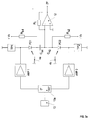
- the circuits shown in Figures 1 and 2 are particular for use in the field of microwaves and millimeter waves suitable and can be used for analog signal transmission between an input part (e.g. radar reception and Transmitting part) and a signal processing unit (not shown) serve, the transmitted signals via an inventive Receiving device are supplied.
- an input part e.g. radar reception and Transmitting part
- a signal processing unit not shown
- On A special application is tunable ECM (Electronic Counter Measure) / ESM (Electronic Support Measure) receiver and communication systems.
- the input part essentially comprises an antenna 1, an RF amplifier 2 and a laser diode 3, the light modulated with the RF voltage to be transmitted and then in an optical fiber 4 is coupled.
- the receiving device at the end of the transmission path includes a beam splitter 10, at the input of which the optical Fiber 4 is connected to generate a first and of a second partial beam, each of which has a first or a second optical fiber piece 4a, 4b are guided.
- the first optical fiber piece 4a is a delay element 11a switched, the first partial beam with a phase shift of approximately 180 ° with respect to the second partial beam acted upon.
- the outputs of the two fiber pieces 4a, 4b are at the Inputs of an optical mixer 12, based on the figures 3a to 3d will be explained. Finally, with the mixer is also connected to an oscillator 13, the one Voltage generated at a frequency with which the received RF signal converted to a desired IF signal voltage can be.
- an optical delay line 11a of length is preferably switchable for comparison or adaptation to the frequency of the RF signal and can therefore be implemented in a relatively broadband manner
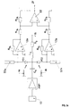
- the structure shown in Figure 2 differs from that first structure according to Figure 1 essentially by the other Type of delay element 11b. This is through one dispersive fiber piece in connection with an agent 3a to generate an adjustable bias for the laser diode formed, the delay due to change the bias on the laser diode leading to a change the operating wavelength and thus the swell or Run time in the dispersive fiber leads is set.
- Figure 3a shows a first embodiment of an opto-electrical push-pull mixer according to the invention.
- the first partial beam guided over the first fiber piece 4a is directed onto a first photodiode PD1, while the second partial beam passing over the second fiber piece 4b is incident on a second photodiode PD2.
- the photodiodes are connected in series and are biased in a known manner in the reverse direction via a resistor Rb1, Rb2 with a bias voltage + Vb or -Vb.
- two capacitors C S1 , C S2 are used between the cathode of the first photodiode PD1 and the anode of the second photodiode PD2.
- the voltage generated by the oscillator 13 is via a first low-impedance amplifier AMP1 to the anode of the first Photodiode PD1 applied.
- the oscillator voltage will also with a phase shifter 13a in phase by about Shifted 180 ° and then over a second low impedance AMP2 amplifier to the cathode of the second photodiode PD2 led.
- the respective low-pass filter represents the ground reference point for that generated in the photodiode PD1 or PD2 Mixed current (IF signal) safe.
- AMP1 e.g. GaAs amplifier
- an operational amplifier connected as a transimpedance amplifier 12 is provided, the inverting input of which has an alternating current connection (via the capacitors C S1 , C S2 ) to the cathode of the first photodiode PD1 and the anode of the second photodiode PD2.
- the non-inverting input is connected to ground.
- the transimpedance amplifier 12 is also fed back with a corresponding resistor R t .
- the differential frequency voltage which arises in the first or second photodiode PD1, PD2 is present in the same phase position at the connection point of the capacitors C S1 , C S2 with the transimpedance amplifier 12 in relation to ground potential.
- the first and the second photodiode PD1, PD2 are driven in alternation over time.
- the oscillator signal drives the photodiodes in common mode.
- the conversion and mixer losses only occur here one element and are therefore lower overall and also easier to influence than the known one Circuit according to Figure 5. Furthermore, the transimpedance amplifier 12 a significantly lower noise amplification than with the known RF amplifier 6 according to FIG Case is.
- the second embodiment according to FIG. 3b differs from the first embodiment according to FIG. 3a essentially in that the photodiodes are connected in anti-series (ie the second photodiode is polarized in reverse to the circuit in FIG. 3a) in that the two capacitors C S1 , C S2 are omitted and that the anodes of the photodiode PD1 or PD2 are supplied with an equally polarized, negative bias voltage -Vb via a series circuit comprising a series resistor Rb1 and a low-pass filter TP1 or a series resistor Rb2 and a low-pass filter TP2 for biasing in the blocking region.
- the two photodiodes PD1, PD2 are via the 180 ° coupler 13a and the respectively preferably low-resistance first and second amplifier AMP1, AMP2 driven in push-pull.
- the connection point of the cathodes of the two photodiodes PD1, PD2 is due to the push-pull drive from the signal of the oscillator isolated.
- the DC circuit will via the low-impedance input of the transimpedance amplifier 12 closed.
- the low pass TP1 or TP2 is at the connection point with the anodes of the first and second photodiodes PD1, PD2 a high-resistance input resistor for the oscillator signal and a low-resistance input resistor for the IF signal.
- the signal is modulated again with a phase shift of 180 ° over the optical Fibers 4a and 4b.
- the 180 ° coupler 13a is omitted and the signal from the oscillator 13 is applied directly to an amplifier AMP.
- the output signal of the amplifier is fed via a capacitor C S to the interconnected cathodes of the anti-serial photodiode PD1, PD2.
- a positive reverse voltage + Vb is also present at this connection point via a resistor Rb and an inductance Lb.
- the anodes of the photodiodes are each connected to a stub line 52a, 52b, which is open at the end and each has a length of about a quarter of the wavelength, which produce a virtual short circuit on the anodes by means of impedance transformation.
- an inverting input of a first and a second amplifier 12a, 12b (preferably transimpedance amplifier) is connected to the anodes of the two photodiodes, which is fed back via a resistor R ta , R tb .
- the two outputs of the amplifiers 12a, 12b are each led via a resistor R1a, R1b to the input of a differential amplifier 55, which is connected to resistors R2a, R2b.
- the IF signal is present at the output of this differential amplifier 55.
- the function of this embodiment differs in essential in that of the first and second embodiments, that the two photodiodes through the amplifier AMP at the connection point of their cathodes in common mode be controlled. With the through the stub lines 52a, 52b generated short circuits will be the corresponding Level control ensured.
- the DC circuit closes to ground via the low impedance input of the Transimpedance amplifier.
- the intermediate frequency current is on tapped the anodes of the two photodiodes PD1, PD2 and with the first and second amplifiers 12a, 12b in corresponding Tensions implemented.
- the output signals of this Amplifiers are superimposed in phase at the output of the Differential amplifier 55 emitted as an IF signal.
- This third embodiment also has the advantage of being common Cathode connection of the photodiodes, so that a Integration on a chip is possible. Beyond that only one oscillator amplifier AMP required. Through the lower load on the transimpedance amplifier (by each only one photodiode) can eventually be a larger one Bandwidth and better stability can be achieved.
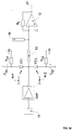
- FIG. 3d finally shows a fourth embodiment of the invention, in which the photodiodes are connected in series as in the first embodiment.
- the connection point of the photodiodes is connected to the output of the low-resistance amplifier AMP and to a high-resistance line 53 with a length of about a quarter of the wavelength, at the output of which a low-resistance stub 54 with approximately the same length and the inverting input of the feedback via the resistor R t Transimpedance amplifier 12 is present.
- the cathode of the second photodiode PD2 is connected to a block capacitor C P2 connected to ground and to a resistor Rb2, via which a positive bias voltage + Vb is supplied.
- the optical signal control in this case in phase over the optical fibers 4c1, 4c2, so that the optical Delay line 11a according to Figure 1 or the device 3a to generate an adjustable bias for the Laser diode 3 and the optical delay element 11b according to Figure 2 are not required.
- the photodiodes PD1, PD2 are driven at their connection point by the pump signal of the preferably low-impedance amplifier AMP.
- the signal path to ground is ensured via the two block capacitors C P1 , C P2 .
- the two line elements 53, 54 form a bandstop filter and suppress the pump signal (oscillator) at the IF output.
- the high input resistance on the line elements in the area of the pump signal frequency prevents the signal matching between the amplifier AMP and the photodiodes PD1, PD2 from being impaired.
- the photodiodes are biased with the negative or positive bias voltage -Vb, + Vb in the blocking region of their characteristic.
- the individual IF currents at the two photodiodes PD1, PD2 are again superimposed constructively at the connection point and are implemented in the manner described above by means of the transimpedance amplifier 12 and are present as an IF signal at the IF output.
- the main advantage of this fourth embodiment is primarily due to the very low circuit complexity. It is only an optical power divider, but not one Optical phase shifter required. However, by means of of the band-stop filter formed from the line elements 53, 54 a separation of the oscillator frequency from the Intermediate frequency can be made.
- FIG 4 finally shows a broadband transmission system for an optical link, with the same elements as in Figures 1 and 2 with the same reference numerals are designated.
- the input part in turn essentially comprises an antenna 1, an RF amplifier 2 and a laser diode 3, the Light modulated with the RF voltage to be transmitted and then coupled into an optical fiber 4.
- an optical in the optical transmission path Amplifier 41 inserted, but in general only with more than four receiving channels connected in parallel is required.
- the receiving channels are preferably designed in accordance with Figure 1 and are each at a predetermined reception frequency Voted.
- Each reception channel thus comprises a beam splitter 10 whose input the optical fiber 4 is connected to Generation of a first and a second partial beam, the in each case via a first or a second optical fiber piece 4a, 4b are performed.
- a delay element 11a is connected, which the first partial beam with a phase shift of approximately 180 ° applied to the second beam.
- the outputs of the two fiber pieces 4a, 4b are at the Inputs of an optical mixer 12, as it is based on the Figures 3a to 3c (and - if the delay element is dispensed with 11a - also Fig. 3d) was explained. Finally is connected to the mixer also an oscillator 13, the one Voltage generated at a frequency with which the received RF signal is converted to a desired IF signal.
Landscapes
- Physics & Mathematics (AREA)
- Electromagnetism (AREA)
- Engineering & Computer Science (AREA)
- Computer Networks & Wireless Communication (AREA)
- Signal Processing (AREA)
- Optical Communication System (AREA)
Applications Claiming Priority (4)
| Application Number | Priority Date | Filing Date | Title |
|---|---|---|---|
| DE19830897 | 1998-07-10 | ||
| DE19830897 | 1998-07-10 | ||
| DE19848723 | 1998-10-22 | ||
| DE19848723A DE19848723A1 (de) | 1998-07-10 | 1998-10-22 | Empfangseinrichtung für eine optische HF-Signalübertragungsstrecke |
Publications (3)
| Publication Number | Publication Date |
|---|---|
| EP0971492A2 true EP0971492A2 (fr) | 2000-01-12 |
| EP0971492A3 EP0971492A3 (fr) | 2004-01-02 |
| EP0971492B1 EP0971492B1 (fr) | 2005-09-14 |
Family
ID=26047322
Family Applications (1)
| Application Number | Title | Priority Date | Filing Date |
|---|---|---|---|
| EP99113206A Expired - Lifetime EP0971492B1 (fr) | 1998-07-10 | 1999-07-08 | Récepteur de liaison de transmission optique de signal HF |
Country Status (3)
| Country | Link |
|---|---|
| EP (1) | EP0971492B1 (fr) |
| AT (1) | ATE304757T1 (fr) |
| DE (1) | DE59912543D1 (fr) |
Cited By (1)
| Publication number | Priority date | Publication date | Assignee | Title |
|---|---|---|---|---|
| US12379617B2 (en) | 2022-02-01 | 2025-08-05 | Universität Paderborn | Electro-optical mixer |
Family Cites Families (6)
| Publication number | Priority date | Publication date | Assignee | Title |
|---|---|---|---|---|
| DE3431896A1 (de) * | 1984-08-30 | 1986-03-13 | Philips Patentverwaltung Gmbh, 2000 Hamburg | Verfahren zur korrektur der signalamplitude optischer nachrichtenempfaenger |
| US4697284A (en) * | 1986-05-08 | 1987-09-29 | American Telephone And Telegraph Company, At&T Bell Laboratories | Single-photodiode optical heterodyne mixers |
| JPH02162330A (ja) * | 1988-12-16 | 1990-06-21 | Hitachi Ltd | 偏波ダイバシティ光受信方法とその装置および中間周波数安定化方法 |
| JPH04278737A (ja) * | 1991-03-06 | 1992-10-05 | Kokusai Denshin Denwa Co Ltd <Kdd> | コヒーレント光受信器 |
| JP3191062B2 (ja) * | 1992-03-03 | 2001-07-23 | 株式会社アドバンテスト | 周波数変換装置 |
| JPH08511929A (ja) * | 1994-04-12 | 1996-12-10 | フィリップス、エレクトロニクス、ネムローゼ、フェンノートシャップ | 低中間周波数を有するヘテロダイン受信機 |
-
1999
- 1999-07-08 EP EP99113206A patent/EP0971492B1/fr not_active Expired - Lifetime
- 1999-07-08 AT AT99113206T patent/ATE304757T1/de not_active IP Right Cessation
- 1999-07-08 DE DE59912543T patent/DE59912543D1/de not_active Expired - Fee Related
Cited By (1)
| Publication number | Priority date | Publication date | Assignee | Title |
|---|---|---|---|---|
| US12379617B2 (en) | 2022-02-01 | 2025-08-05 | Universität Paderborn | Electro-optical mixer |
Also Published As
| Publication number | Publication date |
|---|---|
| EP0971492A3 (fr) | 2004-01-02 |
| EP0971492B1 (fr) | 2005-09-14 |
| ATE304757T1 (de) | 2005-09-15 |
| DE59912543D1 (de) | 2005-10-20 |
Similar Documents
| Publication | Publication Date | Title |
|---|---|---|
| DE69630492T2 (de) | Mikrowellenmischerschaltung | |
| DE69224866T2 (de) | Radarsender mit FET Schaltern | |
| DE2944642C2 (de) | Symmetrische Mischstufe | |
| DE102008015160B4 (de) | Detektoreinrichtung und korrespondierendes Verfahren | |
| DE102011005688A1 (de) | Halbleiterschalter, Sende-Empfangsgerät, Sender und Empfänger | |
| EP1191697B1 (fr) | Oscillateur local pour la génération d'un signal HF pour le mélange direct par photodiodes à avalanches | |
| DE19955849B4 (de) | Phasenschieber | |
| DE3612657A1 (de) | Frequenzumsetzungsschaltung fuer hochfrequenzsignale | |
| DE69305036T2 (de) | Optischer Sender-Empfänger für optische Datenübertragung und Schalteinrichtung | |
| DE68923854T2 (de) | Optischer Breitbandempfänger. | |
| DE2816915A1 (de) | Mischelement | |
| DE3817772A1 (de) | Phasenschieberkombinator | |
| DE2649233C3 (de) | Frequenzverknüpfungsschaltung | |
| EP0971492B1 (fr) | Récepteur de liaison de transmission optique de signal HF | |
| DE102005037877A1 (de) | Diodenmischer | |
| EP0288418B1 (fr) | Procédé pour la transmission optique d'informations à réception hétérodyne | |
| DE69310576T2 (de) | Frequenzumsetzer | |
| EP1488549B1 (fr) | Recepteur a fibres optiques presentant une meilleure bande passante | |
| DE3507779A1 (de) | Ueberlastschutz fuer hf-empfaenger | |
| EP0717514A2 (fr) | Dispositif émetteur optique pour système de télécommunication optique associé à un système radio | |
| DE19848723A1 (de) | Empfangseinrichtung für eine optische HF-Signalübertragungsstrecke | |
| DE4314406C2 (de) | Gruppenantenne mit optischem Strahlformungs-Netzwerk | |
| DE19902346A1 (de) | Kopplungsstruktur als Signalschalter | |
| DE3004019C2 (de) | Einrichtung zur Frequenzumwandlung für einen Mikrowellen-Empfänger oder -Sender | |
| DE10065353B4 (de) | Lokaloszillator zur Erzeugung eines HF-Signals zur Direktmischung mittels Avalanche-Fotodioden |
Legal Events
| Date | Code | Title | Description |
|---|---|---|---|
| PUAI | Public reference made under article 153(3) epc to a published international application that has entered the european phase |
Free format text: ORIGINAL CODE: 0009012 |
|
| AK | Designated contracting states |
Kind code of ref document: A2 Designated state(s): AT BE CH CY DE DK ES FI FR GB GR IE IT LI LU MC NL PT SE |
|
| AX | Request for extension of the european patent |
Free format text: AL;LT;LV;MK;RO;SI |
|
| RAP1 | Party data changed (applicant data changed or rights of an application transferred) |
Owner name: EADS DEUTSCHLAND GMBH |
|
| PUAL | Search report despatched |
Free format text: ORIGINAL CODE: 0009013 |
|
| AK | Designated contracting states |
Kind code of ref document: A3 Designated state(s): AT BE CH CY DE DK ES FI FR GB GR IE IT LI LU MC NL PT SE |
|
| AX | Request for extension of the european patent |
Extension state: AL LT LV MK RO SI |
|
| RIC1 | Information provided on ipc code assigned before grant |
Ipc: 7H 04B 10/148 B Ipc: 7H 04B 10/158 A |
|
| 17P | Request for examination filed |
Effective date: 20040506 |
|
| 17Q | First examination report despatched |
Effective date: 20040628 |
|
| AKX | Designation fees paid |
Designated state(s): AT CH DE FR GB LI |
|
| GRAP | Despatch of communication of intention to grant a patent |
Free format text: ORIGINAL CODE: EPIDOSNIGR1 |
|
| GRAS | Grant fee paid |
Free format text: ORIGINAL CODE: EPIDOSNIGR3 |
|
| GRAA | (expected) grant |
Free format text: ORIGINAL CODE: 0009210 |
|
| AK | Designated contracting states |
Kind code of ref document: B1 Designated state(s): AT CH DE FR GB LI |
|
| REG | Reference to a national code |
Ref country code: GB Ref legal event code: FG4D Free format text: NOT ENGLISH |
|
| REG | Reference to a national code |
Ref country code: CH Ref legal event code: EP |
|
| REF | Corresponds to: |
Ref document number: 59912543 Country of ref document: DE Date of ref document: 20051020 Kind code of ref document: P |
|
| GBT | Gb: translation of ep patent filed (gb section 77(6)(a)/1977) |
Effective date: 20051114 |
|
| ET | Fr: translation filed | ||
| PGFP | Annual fee paid to national office [announced via postgrant information from national office to epo] |
Ref country code: FR Payment date: 20060714 Year of fee payment: 8 Ref country code: DE Payment date: 20060714 Year of fee payment: 8 |
|
| PGFP | Annual fee paid to national office [announced via postgrant information from national office to epo] |
Ref country code: GB Payment date: 20060720 Year of fee payment: 8 |
|
| PLBE | No opposition filed within time limit |
Free format text: ORIGINAL CODE: 0009261 |
|
| STAA | Information on the status of an ep patent application or granted ep patent |
Free format text: STATUS: NO OPPOSITION FILED WITHIN TIME LIMIT |
|
| PG25 | Lapsed in a contracting state [announced via postgrant information from national office to epo] |
Ref country code: LI Free format text: LAPSE BECAUSE OF NON-PAYMENT OF DUE FEES Effective date: 20060731 Ref country code: CH Free format text: LAPSE BECAUSE OF NON-PAYMENT OF DUE FEES Effective date: 20060731 |
|
| 26N | No opposition filed |
Effective date: 20060615 |
|
| REG | Reference to a national code |
Ref country code: CH Ref legal event code: PL |
|
| PG25 | Lapsed in a contracting state [announced via postgrant information from national office to epo] |
Ref country code: AT Free format text: LAPSE BECAUSE OF NON-PAYMENT OF DUE FEES Effective date: 20060708 |
|
| GBPC | Gb: european patent ceased through non-payment of renewal fee |
Effective date: 20070708 |
|
| PG25 | Lapsed in a contracting state [announced via postgrant information from national office to epo] |
Ref country code: DE Free format text: LAPSE BECAUSE OF NON-PAYMENT OF DUE FEES Effective date: 20080201 |
|
| PG25 | Lapsed in a contracting state [announced via postgrant information from national office to epo] |
Ref country code: GB Free format text: LAPSE BECAUSE OF NON-PAYMENT OF DUE FEES Effective date: 20070708 |
|
| REG | Reference to a national code |
Ref country code: FR Ref legal event code: ST Effective date: 20080331 |
|
| PG25 | Lapsed in a contracting state [announced via postgrant information from national office to epo] |
Ref country code: FR Free format text: LAPSE BECAUSE OF NON-PAYMENT OF DUE FEES Effective date: 20070731 |