EP0971495A2 - Optisches Übertragungssystem mit Reduzierung des Dispersionseffektes dritter Ordnung - Google Patents
Optisches Übertragungssystem mit Reduzierung des Dispersionseffektes dritter Ordnung Download PDFInfo
- Publication number
- EP0971495A2 EP0971495A2 EP99401729A EP99401729A EP0971495A2 EP 0971495 A2 EP0971495 A2 EP 0971495A2 EP 99401729 A EP99401729 A EP 99401729A EP 99401729 A EP99401729 A EP 99401729A EP 0971495 A2 EP0971495 A2 EP 0971495A2
- Authority
- EP
- European Patent Office
- Prior art keywords
- optical
- optical fiber
- order dispersion
- length
- transmission path
- Prior art date
- Legal status (The legal status is an assumption and is not a legal conclusion. Google has not performed a legal analysis and makes no representation as to the accuracy of the status listed.)
- Granted
Links
Images


Classifications
-
- H—ELECTRICITY
- H04—ELECTRIC COMMUNICATION TECHNIQUE
- H04B—TRANSMISSION
- H04B10/00—Transmission systems employing electromagnetic waves other than radio-waves, e.g. infrared, visible or ultraviolet light, or employing corpuscular radiation, e.g. quantum communication
- H04B10/25—Arrangements specific to fibre transmission
- H04B10/2507—Arrangements specific to fibre transmission for the reduction or elimination of distortion or dispersion
- H04B10/2513—Arrangements specific to fibre transmission for the reduction or elimination of distortion or dispersion due to chromatic dispersion
- H04B10/2525—Arrangements specific to fibre transmission for the reduction or elimination of distortion or dispersion due to chromatic dispersion using dispersion-compensating fibres
- H04B10/25253—Arrangements specific to fibre transmission for the reduction or elimination of distortion or dispersion due to chromatic dispersion using dispersion-compensating fibres with dispersion management, i.e. using a combination of different kind of fibres in the transmission system
Definitions
- the present invention relates to an optical transmission system for transmitting optical signals using optical fiber.
- optical fiber non-linearity typically causes the phenomenon described below.
- the self-phase modulation effect described above expands the spectrum of the signal light itself, therefore increasing the deterioration in the signal light waveform due to chromatic dispersion in the optical fiber.
- Chromatic dispersion in the optical fiber which is the cause of this waveform deterioration typically means second order dispersion or higher.
- four-wave mixing and cross-phase modulation depend on the difference in group velocity between optical signals of differing wavelengths or between the optical signal and light noise.
- the size of the interaction becomes smaller as the difference in group velocity becomes larger.
- This difference in group velocity is roughly proportional to the second order dispersion value, so that the second order dispersion value may be made large in order to reduce the four-wave mixing and cross-phase modulation effects.
- a conventional transmission path for satisfying these reciprocal conditions is arranged as shown in FIG. 7.
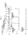
- FIG. 7 is a diagram showing the arrangement of a conventional transmission path.
- B1 shows the physical arrangement of the transmission path
- B2 shows the distribution of the second order dispersion values of the transmission path shown in B1
- B3 shows the distribution of the third order dispersion values of the transmission path shown in B1.
- unit transmission paths consisting of transmitting fiber 30, optical amplifier 32, transmission fiber 34, optical amplifier 36 and dispersion compensating fiber 38 are connected in a cascade.
- Second order dispersion is not zero in transmission fibers 30,34, but rather has a negative dispersion value in the example shown in FIG. 7.
- dispersion compensating fiber 38 is for compensating for the dispersion caused when the optical signal is propagated through transmission fibers 30,34, and has a positive second order dispersion value in the example shown in FIG. 7.
- the conventional optical transmission system takes into consideration only the second order dispersion value and is designed to make this second order dispersion value zero. Therefore, the third and higher dispersion possessed by optical fibers which are typically employed does not become zero.
- an examination of the third order dispersion value for example, reveals that transmission fiber 30, transmission fiber 34 and dispersion compensating fiber 38 all have third order dispersion values which are positive, with this dispersion being uncompensated.
- the optical signal which has propagated along the transmission path is effected by the third or higher dispersion possessed by the optical fiber. Because conventional optical systems do not take third and higher order dispersion into consideration at all, the entire transmission path is effected.
- the third order dispersion is particularly problematic as its dispersion value is relatively the largest in comparison with higher order dispersion. Moreover, when the third order dispersion is not zero, then the second order dispersion value differs according to the wavelength.
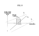
- FIG. 8 is a diagram for explaining the relationship between dispersion characteristics and a signal of multiplexed wavelengths in a conventional optical transmission system.
- the line denoted by symbol C p shows the relationship between the second order dispersion value and the wavelength of dispersion compensating fiber 38 in FIG. 7.
- the line denoted by C n shows the relationship between the second order dispersion value and the wavelength of the transmission fibers 30,34 in FIG. 7.
- the line denoted by C c shows the relationship between the second order dispersion value and the wavelength when transmission fibers 30,34 and dispersion compensating fiber 38 in FIG. 7 are combined.
- the present invention was conceived in consideration of the above-described circumstances and has as its objective the provision of an optical transmission system which resolves the limitations on transmission capacity and transmission distance in a system by means of a simple design, through the provision of a means for restraining the deterioration in transmission characteristics that is the result of accumulation over the entire system of third order dispersion in the optical fiber in an optical transmission system.
- the present invention is characterized in the provision of an optical fiber transmission path in which optical fibers which have at least second and third order dispersion of mutually opposite signs are combined, and in that the optical fibers are disposed so that the average third order dispersion value on the transmission path overall is reduced, and so the length of each optical fiber is sufficiently smaller than the square root of the product of the second order dispersion length, which is determined from the second order dispersion value of the optical fiber and the pulse width of the signal, and the non-linear length, which is determined from the average power of the signal within the optical fiber and the optical fiber nonlinear coefficient of the optical fiber.
- the present invention is further characterized in that the average second order dispersion value on the optical fiber transmission path maintains a finite value in an interval of a distance which is sufficiently longer than the coherence length and the walk-off length, which are determined from the second order dispersion value, the signal pulse width and the wavelength interval between each signal in a signal of multiplexed wavelengths, and in that the optical fiber is disposed so that the second order dispersion value becomes zero in the interval which is smaller than the square root of the product of the second order dispersion length determined by the second order dispersion value and the signal pulse width, and the non-linear length which is determined from the average power of the signal within the optical fiber and the nonlinear coefficient of the optical fiber.
- the present invention is further characterized in the provision of an optical amplifier which operates as an optical repeater, wherein, in the combination of optical fibers, an optical fiber with a small nonlinear coefficient is disposed to the output side of the optical amplifier.
- the present invention is further characterized in that the lengths of the optical fiber having positive sign second and third order dispersion, and the length of the optical fiber having the negative sign second and third order dispersion are equal.
- the present invention is further characterized in that the transmission path has forward and reverse lines, and is provided with a common interval in which the second order dispersion value with respect to the forward line and the reverse line is compensated for to be zero.
- the present invention is further characterized in that the optical fibers at either end of the transmission path are at least 20 kilometers or greater in length and in that the forward and the reverse lines are the same type of optical fiber.
- the present invention employs a combination of optical fibers having second and third order dispersion of mutually opposite signs as the optical fiber transmission path.
- the fundamental light transmitter/receiver and repeater transmission functions are realized by means of optical transmitting and receiving devices, optical fiber transmission path, and optical amplifier and repeater in the same manner as the conventional practice.
- this optical fiber transmission path using a combination of second and third order dispersion having mutually opposite signs, it is possible to avoid the accumulation of third order dispersion over the entire system.
- the disposition of the second order dispersion value is managed so as to reduce the signal deterioration that is caused by self-phase modulation, cross-phase modulation, and four wave mixing.
- the effect therefrom can be prevented in the same way as in the conventional systems which managed only the second order dispersion value.
- the present invention enables a significant easing of the deterioration in transmission characteristics that is caused by optical fiber non-linearity and optical fiber dispersion characteristics.
- the present invention is effective in increasing the system capacity and the transmission distance.
- FIG. 1 is a block diagram showing the structure of an optical transmission system according to one embodiment of the present invention, wherein A1 shows the physical arrangement of the transmission path, A2 shows the distribution of the second order dispersion values on the transmission path shown in A1, and A3 shows the distribution of the third order dispersion value on the transmission path shown in A1.
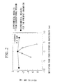
- FIG. 2 is a diagram showing the experimental results for the relative signal-to-noise ratio with respect to the wavelength in the optical transmission system according to one embodiment of the present invention, and experimental results for the relative signal-to-noise ratio with respect to the wavelength in a conventional optical transmission system.
- FIG. 3 is a diagram showing an example of the calculated results for transmission characteristics in the case where, in a two-type optical fiber combination method, the optical fibers have been simply combined so that the second and third order dispersions become zero in each combination of the fibers.
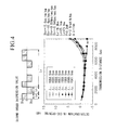
- FIG. 4 is a diagram showing the calculated results for transmission characteristics in an optical transmission system according to one embodiment of the present invention.
- FIG. 5 is a block diagram showing the structure in overview of a transmission path in an optical transmission system according to another embodiment of the present invention.
- FIG. 6 is a diagram showing a modification according to another embodiment of the present invention which takes into consideration damage to a portion of the facility in shallow seas.
- FIG. 7 is a diagram showing the arrangement of a conventional transmission path, wherein B1 shows the physical arrangement of the transmission path, B2 shows the distribution of the second order dispersion value of the transmission path shown in B1, and B3 shows the distribution of the third order dispersion value of the transmission path shown in B1.
- FIG. 8 is a diagram for explaining the relationship between dispersion characteristics and a signal of multiplexed wavelengths in a conventional optical transmission system.
- FIG. 1 is a block diagram showing the structure of an optical transmission system according to one embodiment of the present invention, wherein A1 shows the physical arrangement of the transmission path, A2 shows the distribution of the second order dispersion values on the transmission path shown in A1, and A3 shows the distribution of the third order dispersion values on the transmission path shown in A1.
- transmitting device 10 generates an optical signal of a single wavelength or of multiplexed wavelengths.
- unit transmission paths consisting of positive dispersion fiber 40, negative dispersion fiber 42, optical amplifier 44, positive dispersion fiber 46, negative dispersion fiber 48, optical amplifier 50, positive dispersion fiber 52 and positive dispersion fiber 54, are connected in cascade.
- Positive dispersing optical fibers 40, 46, 52, and 54 have positive sign second and third order dispersion, while the negative dispersion fibers 42 and 48 have negative sign second and third order dispersion.
- the length of positive dispersing optical fibers 40, 46, 52, and 54 is L p
- that of negative dispersion fibers 42 and 48 is L n .
- the second and third order dispersion of positive dispersing optical fibers 40, 46, 52, and 54 are designated as D 2p and D 3p , respectively, while the second and third order dispersion of negative dispersion fibers 42 and 48 are designated as D 2n and D 3n , respectively.
- the intervals in which positive dispersion fibers 40, 46, 52, and 54 and negative dispersion fibers 42 and 48 are combined, i.e., the average second order dispersion value and average third order dispersion value of the unit transmission path, are designated as D 2s and D 3s , respectively.
- the total length of the system is indicated as L.
- the average power per wavelength signal in the optical fiber is designated as P
- the optical fiber nonlinear coefficient is designated as k 2
- the signal pulse width is designated as T 0
- the signal optical wavelength is designated as ⁇ (approximately common to all signal wavelengths)
- the wavelength interval is designated as ⁇ .
- L NL is the non-linear length, and is the scale for the non-linearity of the optical fiber.
- L D2 and L D3 are the second and third order dispersion lengths, respectively, and are the scales for the size of the second and third order dispersions.
- D 2 in the equations (2) through (5) may indicate either D 2p , D 2n , or D 2s .
- D 3 in the equations (2) through (5) may indicate either D 3p , D 3n , or D 3s .
- pulse width as employed in this specification may be defined as the full width at half maximum, the half width at half maximum or the pulse width at which the pulse waveform peak value becomes a value of 1/e (where e is an exponential function).
- L w is the walk-off length and is the scale for the size of cross-phase modulation.
- L coh is the coherence length and is the scale for the size of four-wave mixing at the coherence length.
- coherence length I coh is directed to degenerate four-wave mixing.
- the lengths L p ,L n of the two different fibers have values sufficiently smaller than L D 2 p L NL and L D 2 n L NL respectively, for example, fiber lengths L p ,L n are set to 1/2 or less than the value expressed by this equation.
- FIG. 1 two types of optical fibers are disposed in a single unit transmission path. Clearly, however, it is acceptable for the respective optical fibers to be disposed straddling the repeater interval provided that the aforementioned conditions are satisfied.
- the cross-phase modulation effect and the four-wave mixing effect are reduced by allowing the average second order dispersion value D 2S in the interval in which the two different types of fibers are combined to remain D 2S as a finite value, and not zero.
- deterioration occurs caused by the second order dispersion value D 2s and optical fiber non-linearity.
- compensation is performed so that the second order dispersion and third order dispersion over a given distance L s becomes zero or a sufficiently small value.
- L s at this time must be sufficiently smaller than L D 2 s L NL
- L s at this time must be sufficiently smaller than L D 2 s L NL
- a given distance L s must be sufficiently smaller with respect to 3 L D 3 s L 2 NL
- L D 3 s L NL > 3 L D 3 s L 2 NL there is no problem if L s ⁇ L D 2 s L NL
- L S Since L coh ⁇ L w under ordinary conditions, it is acceptable to set a given distance L S to be a value greater (5-fold greater, for example) than the walk-off length L W (see The Institute of Electronics, Information and Communications Engineers, Optical Communications System Research Committee, OCS 96-57, p. 37, 1996).
- i and j respectively indicate the numbers of the positive dispersion fiber and the negative dispersion fiber within the interval of a given distance L S .
- N and M each indicate the total number of fibers within the interval of a given distance L S .
- positive dispersion fibers 46,52 are disposed to the respective output sides of optical amplifiers 44,50.
- this arrangement assumes that positive dispersion fibers 46,52 have a smaller nonlinear coefficient than negative dispersion fibers 42,48, and takes into consideration the impact from the effect of fiber non-linearity.
- negative dispersion fibers 42,48 have a smaller nonlinear coefficient than positive dispersion fibers 46,52, or when the fibers are arranged to the optical amplifier output side irrespective of the size of the nonlinear coefficient, it is clear that there is no change in the contents described above.
- the system in its entirety according to this embodiment is constructed by repeating the dispersion arrangement within a given distance L S .
- FIG. 2 is a diagram showing the experimental results for the relative signal-to-noise ratio with respect to the wavelength in the optical transmission system according to one embodiment of the present invention, and experimental results for the relative signal-to-noise ratio with respect to the wavelength in a conventional optical transmission system.
- a 10Gb/s NRZ (non-return-to-zero) signal (pulse width 100ps) of a single wavelength was output from the transmitting device 10 shown in FIG. 1, and transmitted by disposing the optical amplifiers 44,50 at approximately 50 km intervals. Note that the pulse power was 0.2 mW, and the entire length of the transmission path was 9000 km.
- the second and third order dispersion values of the transmission fiber 30 shown in FIG. 7 were set to -1 Ps/nm/km and 0.07 Ps/nm 2 /km, respectively, and a dispersion compensating fiber 38 was inserted in which the second order dispersion becomes zero at every 500 km transmission.
- the third dispersing value was reduced to 0.01 Ps/nm 2 /km.
- FIG. 3 is a diagram showing an example of the calculated results for transmission characteristics in the case where, in a two-type optical fiber combination method, the optical fibers have been simply combined so that the second and third order dispersions become zero.
- FIG. 4 is a diagram showing the calculated results for transmission characteristics in an optical transmission system according to one embodiment of the present invention.
- the average second order dispersion value D 2S in the interval in which the two different types of fibers are combined is simply set to zero.
- the average second order dispersion value D 2S remains as a finite value.
- the optical transmission cable which is employed in an actual optical transmission system, it has the optical fiber for the forward line and the optical fiber for the reverse line forming a pair.
- the optical transmission cable is typically formed by providing a plurality of these optical fiber pairs.
- the four combination are an optical transmission cable formed of positive dispersion fibers for both the forward and reverse lines; an optical transmission cable in which the forward line is a positive dispersion fiber and the reverse line is a negative dispersion fiber; an optical transmission cable in which the forward line is a negative dispersion fiber and the reverse line is a positive dispersion fiber; and an optical transmission cable formed of negative dispersion fibers for both the forward and reverse lines.
- the optical transmission system is comprised of a transmitting device which outputs a signal of a single wavelength or of multiplexed wavelengths; a transmission path, which is formed of a repetition of an optical transmission path for sending the signal output from the transmitting device and a repeater for amplifying the output of signals damped by loss along the optical transmission path; and a receiving device for receiving the signal sent by the transmission path.
- FIG. 5 is a block diagram showing the structure in overview of the transmission path in the optical transmission system according to another embodiment of the present invention.
- FIG. 5 shows an example of a transmission path consisting of one forward line US and one reverse line DS.
- 60-1 ⁇ 60-n indicates repeater for amplifying the power of the signal damped by loss along the optical transmission path.
- Repeater 60-1 ⁇ 60-n are provided with respective optical amplifiers 62a,62b for amplifying the optical signals which are propagating along the forward line US and reverse line DS.
- the numeral 64 consists of a positive dispersion fiber 63a having second and third positive dispersion, and a negative dispersion fiber 63b having second and third negative dispersion.
- the lengths of positive dispersion fiber 63a and negative dispersion fiber 63b are designed to be equivalent.
- the numeral 66 indicates an optical transmission path having a positive dispersion fiber 63a having second and third positive dispersion, and a negative dispersion fiber 63b having second and third negative dispersion.
- Optical transmission paths 64,66 differ in that positive dispersion fiber 63a is disposed to the forward line US and negative dispersion fiber 63b is disposed to the reverse line DS in optical transmission path 64, while this arrangement is reversed in optical transmission path 66.
- the transmission path in the optical transmission system is basically formed by repeatedly disposing as units, optical transmission path 64, optical transmission path 66, and repeater 60 (the following explanation will be made using repeaters 60 when there is no discrimination made between repeaters 60-1 ⁇ 60-n).
- intervals are provided at sites along the transmission path for compensating for second and third order dispersion accumulation in the optical signal which has propagated along the transmission path.
- Optical transmission path 68 is provided to these intervals.
- the same type of optical fibers 69 of equal length are disposed to the forward line US and reverse line DS in optical transmission path 68.
- Optical transmission paths 64 and 66 have completely the same structure, so that the same type of fiber may be employed provided the connection is changed. Thus, while a discrimination is made between optical transmission paths 64,66 in FIG. 5, in actuality a transmission path may be formed using only one type of optical transmission path 62 in each repeater interval. Accordingly, this embodiment is designed so that the lengths of optical fibers 63a,63b are equal in each repeater interval which is formed of two different types of optical fibers 63a,63b having mutually opposite dispersion signs. For this reason, it is possible to form a transmission path using only one type of optical transmission path 62 in this interval. Thus, it is possible for the entire transmission path to be formed using only one type of optical transmission path 62.
- an optical transmission path 68 consisting of equal length optical fibers 69 in which the forward line US and the reverse line DS are of the same type is disposed at sites along the transmission path in the intervals for compensating for the accumulation of second and third order dispersion in the optical signal which has propagated along the transmission path. For this reason, it is not necessary to use various types of cables, thus construction and maintenance is facilitated.
- Damage to the communications line due to severing of an undersea cable or the like is typically a serious problem in an undersea transmission system. This type of severing accident is primarily due to human error. Accordingly, the majority of these accidents occur in shallow ocean areas. Typically, water depth increases as one moves away from the coast. Thus, it may be viewed that this type of damage occurs to the portion of the system near the terminals, i.e., within an interval of 100 km from either station.
- FIG. 6 is a diagram showing a modification according to another embodiment of the present invention in which damage in a shallow ocean area is considered.
- the area indicated by symbol fl is a diagram showing an example of the water depth in an interval along the undersea. As shown in this figure, the water depth is shallow at 80,82, and increases with greater distance from the shore.
- FIG. 6 shows the case where the transmission path consists of a total of 4 lines, i.e., forward line US1,US2 and reverse lines DS1,DS2.
- an optical transmission path 72 is employed which has two each of roughly equal length positive dispersion fiber 63a and negative dispersion fiber 63b shown in FIG. 5.
- the transmission path is formed employing as units two optical transmission paths 72,72 and undersea repeater 70. These two transmission paths are connected in mutually opposite directions as in the case shown in FIG. 5.
- This embodiment is characterized in that shallow ocean areas 80,82 are provided with an optical transmission path consisting of optical fiber in which the forward and reverse lines are of the same type.
- FIG. 1 shows the example shown in FIG.
- optical transmission paths 74,74 are disposed to shallow ocean areas 80,82 having equal length optical fibers which have second and third positive dispersion for all the forward lines US1,US2 and the reverse lines DS1,DS2.
- the length of the optical fiber having optical transmission path 74 is preferably 20 kilometers or more in view of the distance of the shallow ocean area.
- the first embodiment described above was based on the disposition of an optical fiber such that the length of the optical fiber is sufficiently smaller than the square root of the product of the second order dispersion length, which is determined from the second order dispersion value of the optical fiber and the pulse width of the signal, and the non-linear length, which is determined from the average power of the signal within the optical fiber and the optical fiber nonlinear coefficient.
- the length of the optical fiber which is employed in the shallow ocean area of the forward and reverse lines was limited.
- the modification according to this other embodiment appears to contradict the first embodiment.
- the length of an undersea cable is typically in the range of several hundred to several thousand kilometers. Since the length of the shallow ocean area is 20 ⁇ 100 km, employing optical transmission path 74 in the shallow ocean area enables this effect to be of an order which may be ignored, even when the conditions in the first embodiment are not satisfied locally.
- FIGS. 5 and 6 show examples in which the number of forward and reverse lines are from 1 to 2, however the present invention is of course not limited by the line number.
Landscapes
- Physics & Mathematics (AREA)
- Electromagnetism (AREA)
- Engineering & Computer Science (AREA)
- Computer Networks & Wireless Communication (AREA)
- Signal Processing (AREA)
- Optical Communication System (AREA)
Applications Claiming Priority (2)
| Application Number | Priority Date | Filing Date | Title |
|---|---|---|---|
| JP19636498 | 1998-07-10 | ||
| JP19636498 | 1998-07-10 |
Publications (3)
| Publication Number | Publication Date |
|---|---|
| EP0971495A2 true EP0971495A2 (de) | 2000-01-12 |
| EP0971495A3 EP0971495A3 (de) | 2004-01-07 |
| EP0971495B1 EP0971495B1 (de) | 2006-02-15 |
Family
ID=16356632
Family Applications (1)
| Application Number | Title | Priority Date | Filing Date |
|---|---|---|---|
| EP99401729A Expired - Lifetime EP0971495B1 (de) | 1998-07-10 | 1999-07-09 | Optisches Übertragungssystem mit Reduzierung des Dispersionseffektes dritter Ordnung |
Country Status (4)
| Country | Link |
|---|---|
| US (1) | US6307985B1 (de) |
| EP (1) | EP0971495B1 (de) |
| CA (1) | CA2277409C (de) |
| DE (1) | DE69929869T2 (de) |
Cited By (5)
| Publication number | Priority date | Publication date | Assignee | Title |
|---|---|---|---|---|
| FR2805416A1 (fr) * | 2000-02-17 | 2001-08-24 | Fujitsu Ltd | Systeme de communication optique et procede de reparation de section de transmission |
| WO2004034613A3 (en) * | 2002-10-11 | 2004-06-03 | Corning Inc | Devices and methods for dynamic dispersion compensation |
| EP1447697A3 (de) * | 2003-02-11 | 2004-12-29 | Tyco Telecommunications (US) Inc. | Verfahren zum Reparieren eines dispersionskompensierten Kabelsystems und Ersatzkabel zum Gebrauch hierin |
| US7079737B1 (en) | 2002-10-11 | 2006-07-18 | Corning Incorporated | Devices and methods for dynamic dispersion compensation |
| US7813035B2 (en) * | 2006-05-18 | 2010-10-12 | Polaronyx, Inc. | Nonlinearity and dispersion management for pulse reshaping in high energy fiber amplifier |
Families Citing this family (52)
| Publication number | Priority date | Publication date | Assignee | Title |
|---|---|---|---|---|
| GB9524203D0 (en) * | 1995-11-27 | 1996-01-31 | British Tech Group | Optical communications |
| GB9716230D0 (en) * | 1997-07-31 | 1997-10-08 | British Tech Group | Optical fibre communication system |
| WO2001018572A1 (en) * | 1999-09-06 | 2001-03-15 | Sumitomo Electric Industries, Ltd. | Optical fiber line, optical transmission line, production method of optical cables and method of laying optical transmission lines |
| JP2001094510A (ja) * | 1999-09-24 | 2001-04-06 | Ddi Corp | 光伝送システム、光伝送路及び光送信装置 |
| US6473550B1 (en) | 1999-09-27 | 2002-10-29 | Sumitomo Electric Industries, Ltd. | Optical fiber transmission-line |
| JP2001091761A (ja) * | 1999-09-27 | 2001-04-06 | Sumitomo Electric Ind Ltd | 光ファイバ伝送路 |
| US6792209B1 (en) * | 1999-12-22 | 2004-09-14 | At&T Corp. | Method and system for reducing non-linear cross talk in low dispersion optical fiber |
| DE10040226B4 (de) * | 2000-08-17 | 2006-03-09 | Siemens Ag | Optischer Verstärker und optische Verstärkeranordnung mit reduzierter Kreuzphasenmodulation |
| JP4372330B2 (ja) | 2000-10-30 | 2009-11-25 | 富士通株式会社 | 分布型光増幅装置、光通信用の局および光通信システム |
| US6526208B1 (en) * | 2000-11-27 | 2003-02-25 | Nortel Networks Limited | Dispersion managed fiber optic cable and system |
| JP2002232355A (ja) * | 2001-01-31 | 2002-08-16 | Kddi Submarine Cable Systems Inc | 光ファイバ伝送路 |
| WO2002089363A1 (en) * | 2001-04-27 | 2002-11-07 | Ciena Corporation | Method and system for providing dispersion and dispersion slope compensation |
| US7085500B2 (en) * | 2001-04-30 | 2006-08-01 | Lockheed Martin Corp. | Programmable optical vector modulator and method for use in coherent optical communications |
| US20030007216A1 (en) * | 2001-06-21 | 2003-01-09 | Chraplyvy Andrew Roman | Long haul transmission in a dispersion managed optical communication system |
| JP4022860B2 (ja) * | 2002-03-27 | 2007-12-19 | 日本電気株式会社 | 波長分割多重光ファイバ伝送路 |
| US7400835B2 (en) * | 2002-08-30 | 2008-07-15 | Ciena Corporation | WDM system having chromatic dispersion precompensation |
| WO2004073184A2 (en) * | 2003-02-13 | 2004-08-26 | Corning Incorporated | Devices and methods for dynamic dispersion compensation |
| WO2004114530A2 (en) * | 2003-06-20 | 2004-12-29 | Corvis Corporation | Systems, devices, and methods for controlling non-linear optical interactions |
| US9125562B2 (en) | 2009-07-01 | 2015-09-08 | Avinger, Inc. | Catheter-based off-axis optical coherence tomography imaging system |
| US8062316B2 (en) | 2008-04-23 | 2011-11-22 | Avinger, Inc. | Catheter system and method for boring through blocked vascular passages |
| US9498600B2 (en) | 2009-07-01 | 2016-11-22 | Avinger, Inc. | Atherectomy catheter with laterally-displaceable tip |
| US8644913B2 (en) | 2011-03-28 | 2014-02-04 | Avinger, Inc. | Occlusion-crossing devices, imaging, and atherectomy devices |
| US20100125253A1 (en) * | 2008-11-17 | 2010-05-20 | Avinger | Dual-tip Catheter System for Boring through Blocked Vascular Passages |
| EP2424608B1 (de) | 2009-04-28 | 2014-03-19 | Avinger, Inc. | Trägerkatheter für führungsdraht |
| CA2763324C (en) | 2009-05-28 | 2018-10-23 | Avinger, Inc. | Optical coherence tomography for biological imaging |
| WO2011072068A2 (en) | 2009-12-08 | 2011-06-16 | Avinger, Inc. | Devices and methods for predicting and preventing restenosis |
| US11382653B2 (en) | 2010-07-01 | 2022-07-12 | Avinger, Inc. | Atherectomy catheter |
| JP2013531542A (ja) | 2010-07-01 | 2013-08-08 | アビンガー・インコーポレイテッド | 長手方向に移動可能なドライブシャフトを有するアテローム切除カテーテル |
| US10548478B2 (en) | 2010-07-01 | 2020-02-04 | Avinger, Inc. | Balloon atherectomy catheters with imaging |
| US9949754B2 (en) | 2011-03-28 | 2018-04-24 | Avinger, Inc. | Occlusion-crossing devices |
| JP6356604B2 (ja) | 2011-10-17 | 2018-07-11 | アビンガー・インコーポレイテッドAvinger, Inc. | アテローム切除カテーテルおよびカテーテル用の非接触型作動機構 |
| US9345406B2 (en) | 2011-11-11 | 2016-05-24 | Avinger, Inc. | Occlusion-crossing devices, atherectomy devices, and imaging |
| EP2849661B1 (de) | 2012-05-14 | 2020-12-09 | Avinger, Inc. | Atherektomiekatheter mit bildgebung |
| US9345398B2 (en) | 2012-05-14 | 2016-05-24 | Avinger, Inc. | Atherectomy catheter drive assemblies |
| EP2849636B1 (de) | 2012-05-14 | 2020-04-22 | Avinger, Inc. | Optische kohärenztomografie mit gradientenindexfaser für biologische bildgebung |
| US9036998B2 (en) * | 2012-08-18 | 2015-05-19 | Ofs Fitel, Llc | Long-haul undersea transmission system and fiber |
| US10335173B2 (en) | 2012-09-06 | 2019-07-02 | Avinger, Inc. | Re-entry stylet for catheter |
| US11284916B2 (en) | 2012-09-06 | 2022-03-29 | Avinger, Inc. | Atherectomy catheters and occlusion crossing devices |
| US9498247B2 (en) | 2014-02-06 | 2016-11-22 | Avinger, Inc. | Atherectomy catheters and occlusion crossing devices |
| WO2014142954A1 (en) | 2013-03-15 | 2014-09-18 | Avinger, Inc. | Tissue collection device for catheter |
| US9854979B2 (en) | 2013-03-15 | 2018-01-02 | Avinger, Inc. | Chronic total occlusion crossing devices with imaging |
| CN105228514B (zh) | 2013-03-15 | 2019-01-22 | 阿维格公司 | 光学压力传感器组件 |
| US10130386B2 (en) | 2013-07-08 | 2018-11-20 | Avinger, Inc. | Identification of elastic lamina to guide interventional therapy |
| EP3102127B1 (de) | 2014-02-06 | 2019-10-09 | Avinger, Inc. | Atherektomiekatheter |
| CN107106190B (zh) | 2014-07-08 | 2020-02-28 | 阿维格公司 | 高速慢性全闭塞部横穿装置 |
| EP3322338B1 (de) | 2015-07-13 | 2025-02-12 | Avinger, Inc. | Mikrogeformte anamorphotische reflektorlinse für bildgeführte therapeutische/diagnosekatheter |
| US11278248B2 (en) | 2016-01-25 | 2022-03-22 | Avinger, Inc. | OCT imaging catheter with lag correction |
| CN108882948A (zh) | 2016-04-01 | 2018-11-23 | 阿维格公司 | 具有锯齿状切割器的旋切术导管 |
| CN109475368A (zh) | 2016-06-03 | 2019-03-15 | 阿维格公司 | 具有可拆卸远端的导管装置 |
| CN109414273B (zh) | 2016-06-30 | 2023-02-17 | 阿维格公司 | 具有可塑形的远侧头端的斑块切除导管 |
| EP3781021B1 (de) | 2018-04-19 | 2023-03-22 | Avinger, Inc. | Okklusionskreuzungsvorrichtungen |
| WO2021076356A1 (en) | 2019-10-18 | 2021-04-22 | Avinger, Inc. | Occlusion-crossing devices |
Family Cites Families (5)
| Publication number | Priority date | Publication date | Assignee | Title |
|---|---|---|---|---|
| JPH0923187A (ja) | 1995-07-10 | 1997-01-21 | Fujitsu Ltd | 光伝送システム |
| JP3760557B2 (ja) | 1996-04-15 | 2006-03-29 | 住友電気工業株式会社 | 分散補償ファイバ及びそれを含む光伝送システム |
| US5764841A (en) * | 1996-04-25 | 1998-06-09 | Nippon Telegraph And Telephone Corporation | Optical fiber transmission line, optical fiber transmission system and production method thereof, and optical fiber combining method |
| JPH1073738A (ja) | 1996-06-21 | 1998-03-17 | Furukawa Electric Co Ltd:The | 光伝送用波長多重通信リンク |
| JPH1039154A (ja) | 1996-07-22 | 1998-02-13 | Oki Electric Ind Co Ltd | 光パルス圧縮装置 |
-
1999
- 1999-07-08 CA CA002277409A patent/CA2277409C/en not_active Expired - Lifetime
- 1999-07-08 US US09/348,838 patent/US6307985B1/en not_active Expired - Lifetime
- 1999-07-09 EP EP99401729A patent/EP0971495B1/de not_active Expired - Lifetime
- 1999-07-09 DE DE69929869T patent/DE69929869T2/de not_active Expired - Lifetime
Cited By (7)
| Publication number | Priority date | Publication date | Assignee | Title |
|---|---|---|---|---|
| FR2805416A1 (fr) * | 2000-02-17 | 2001-08-24 | Fujitsu Ltd | Systeme de communication optique et procede de reparation de section de transmission |
| US7164864B2 (en) | 2000-02-17 | 2007-01-16 | Fujitsu Limited | Optical communications system and transmission section repair method |
| WO2004034613A3 (en) * | 2002-10-11 | 2004-06-03 | Corning Inc | Devices and methods for dynamic dispersion compensation |
| US6865328B2 (en) | 2002-10-11 | 2005-03-08 | Corning Incorporated | Positive dispersion optical fiber |
| US7079737B1 (en) | 2002-10-11 | 2006-07-18 | Corning Incorporated | Devices and methods for dynamic dispersion compensation |
| EP1447697A3 (de) * | 2003-02-11 | 2004-12-29 | Tyco Telecommunications (US) Inc. | Verfahren zum Reparieren eines dispersionskompensierten Kabelsystems und Ersatzkabel zum Gebrauch hierin |
| US7813035B2 (en) * | 2006-05-18 | 2010-10-12 | Polaronyx, Inc. | Nonlinearity and dispersion management for pulse reshaping in high energy fiber amplifier |
Also Published As
| Publication number | Publication date |
|---|---|
| US6307985B1 (en) | 2001-10-23 |
| CA2277409C (en) | 2003-02-11 |
| DE69929869D1 (de) | 2006-04-20 |
| CA2277409A1 (en) | 2000-01-10 |
| DE69929869T2 (de) | 2006-11-02 |
| EP0971495B1 (de) | 2006-02-15 |
| EP0971495A3 (de) | 2004-01-07 |
Similar Documents
| Publication | Publication Date | Title |
|---|---|---|
| EP0971495B1 (de) | Optisches Übertragungssystem mit Reduzierung des Dispersionseffektes dritter Ordnung | |
| US6487005B2 (en) | Optical fiber transmission system with chromatic dispersion compensation | |
| US7043099B1 (en) | Device and system for phase conjugate conversion and wavelength conversion | |
| US6157477A (en) | Bidirectional dispersion compensation system | |
| JPH08139670A (ja) | 光増幅中継伝送システム | |
| US5966228A (en) | Optical transmission system and optical repeater | |
| US20020012148A1 (en) | Dispersion compensation in optical communication network and optical communication network | |
| US6427043B1 (en) | Wavelength dispersion compensating method and optical transmission system | |
| US7187868B2 (en) | Wavelength division multiplexing optical transmission system using a spectral inversion device | |
| US6476949B1 (en) | Dispersion compensation in optical fibre transmission | |
| EP2163010B1 (de) | System für passive verschlüsselung und entschlüsselung eines optischen signals | |
| EP1566002B1 (de) | Optisches kommunikationssystem | |
| JP3312885B2 (ja) | 光伝送システム | |
| US7016583B2 (en) | Dispersion management with phase conjugation | |
| Tripathi et al. | Performance study in dispersion compensation techniques with Duobinary format at different bit rates | |
| Gul et al. | Multistage amplified and dispersion compensated ultra-long haul DWDM link with high OSNR | |
| Martensson et al. | Dispersion-managed solitons for 160-Gb/s data transmission | |
| Singh et al. | Analysis of pre-, post-, and symmetrical dispersion compensation techniques using DCF on 40× 10 Gbps WDM-PON system | |
| JP3503720B2 (ja) | ソリトン伝送線路 | |
| Rindhe et al. | Modeling of SMF link for Optical Networks | |
| JP3508898B2 (ja) | 光ソリトン通信伝送路 | |
| US7127178B2 (en) | Optical communication device | |
| JPH1117624A (ja) | 光伝送路 | |
| Caspar et al. | Gb/s NRZ/RZ transmission over 2000 km standard fibre with more than 100 km amplifier spacing | |
| EP1436920B1 (de) | Optisches übertragungssystem mit dispersionsverwaltungssystem |
Legal Events
| Date | Code | Title | Description |
|---|---|---|---|
| PUAI | Public reference made under article 153(3) epc to a published international application that has entered the european phase |
Free format text: ORIGINAL CODE: 0009012 |
|
| AK | Designated contracting states |
Kind code of ref document: A2 Designated state(s): AT BE CH CY DE DK ES FI FR GB GR IE IT LI LU MC NL PT SE |
|
| AX | Request for extension of the european patent |
Free format text: AL;LT;LV;MK;RO;SI |
|
| PUAL | Search report despatched |
Free format text: ORIGINAL CODE: 0009013 |
|
| AK | Designated contracting states |
Kind code of ref document: A3 Designated state(s): AT BE CH CY DE DK ES FI FR GB GR IE IT LI LU MC NL PT SE |
|
| AX | Request for extension of the european patent |
Extension state: AL LT LV MK RO SI |
|
| 17P | Request for examination filed |
Effective date: 20040301 |
|
| 17Q | First examination report despatched |
Effective date: 20040330 |
|
| AKX | Designation fees paid |
Designated state(s): DE FR GB |
|
| GRAP | Despatch of communication of intention to grant a patent |
Free format text: ORIGINAL CODE: EPIDOSNIGR1 |
|
| GRAS | Grant fee paid |
Free format text: ORIGINAL CODE: EPIDOSNIGR3 |
|
| GRAA | (expected) grant |
Free format text: ORIGINAL CODE: 0009210 |
|
| AK | Designated contracting states |
Kind code of ref document: B1 Designated state(s): DE FR GB |
|
| REG | Reference to a national code |
Ref country code: GB Ref legal event code: FG4D |
|
| REF | Corresponds to: |
Ref document number: 69929869 Country of ref document: DE Date of ref document: 20060420 Kind code of ref document: P |
|
| ET | Fr: translation filed | ||
| PLBE | No opposition filed within time limit |
Free format text: ORIGINAL CODE: 0009261 |
|
| STAA | Information on the status of an ep patent application or granted ep patent |
Free format text: STATUS: NO OPPOSITION FILED WITHIN TIME LIMIT |
|
| 26N | No opposition filed |
Effective date: 20061116 |
|
| REG | Reference to a national code |
Ref country code: FR Ref legal event code: PLFP Year of fee payment: 18 |
|
| REG | Reference to a national code |
Ref country code: FR Ref legal event code: PLFP Year of fee payment: 19 |
|
| REG | Reference to a national code |
Ref country code: FR Ref legal event code: PLFP Year of fee payment: 20 |
|
| PGFP | Annual fee paid to national office [announced via postgrant information from national office to epo] |
Ref country code: FR Payment date: 20180725 Year of fee payment: 20 Ref country code: DE Payment date: 20180723 Year of fee payment: 20 |
|
| PGFP | Annual fee paid to national office [announced via postgrant information from national office to epo] |
Ref country code: GB Payment date: 20180719 Year of fee payment: 20 |
|
| REG | Reference to a national code |
Ref country code: DE Ref legal event code: R071 Ref document number: 69929869 Country of ref document: DE |
|
| REG | Reference to a national code |
Ref country code: GB Ref legal event code: PE20 Expiry date: 20190708 |
|
| PG25 | Lapsed in a contracting state [announced via postgrant information from national office to epo] |
Ref country code: GB Free format text: LAPSE BECAUSE OF EXPIRATION OF PROTECTION Effective date: 20190708 |