EP0972693B1 - Mécanisme de verrouillage pour un dispositif d'accouplement - Google Patents
Mécanisme de verrouillage pour un dispositif d'accouplement Download PDFInfo
- Publication number
- EP0972693B1 EP0972693B1 EP99810501A EP99810501A EP0972693B1 EP 0972693 B1 EP0972693 B1 EP 0972693B1 EP 99810501 A EP99810501 A EP 99810501A EP 99810501 A EP99810501 A EP 99810501A EP 0972693 B1 EP0972693 B1 EP 0972693B1
- Authority
- EP
- European Patent Office
- Prior art keywords
- coupling
- lever
- bolt
- arrangement according
- intermediate lever
- Prior art date
- Legal status (The legal status is an assumption and is not a legal conclusion. Google has not performed a legal analysis and makes no representation as to the accuracy of the status listed.)
- Expired - Lifetime
Links
- 238000010168 coupling process Methods 0.000 title claims abstract description 124
- 238000005859 coupling reaction Methods 0.000 title claims abstract description 117
- 230000008878 coupling Effects 0.000 title claims abstract description 116
- 230000007246 mechanism Effects 0.000 title claims abstract description 28
- 238000000034 method Methods 0.000 claims description 5
- 230000008569 process Effects 0.000 claims description 5
- 230000000284 resting effect Effects 0.000 claims 1
- 230000014759 maintenance of location Effects 0.000 abstract 1
- 230000009471 action Effects 0.000 description 3
- 230000000712 assembly Effects 0.000 description 1
- 238000000429 assembly Methods 0.000 description 1
- 238000010276 construction Methods 0.000 description 1
- 238000013016 damping Methods 0.000 description 1
- 230000001419 dependent effect Effects 0.000 description 1
- 238000006073 displacement reaction Methods 0.000 description 1
- 230000007613 environmental effect Effects 0.000 description 1
- 239000007788 liquid Substances 0.000 description 1
- 238000004519 manufacturing process Methods 0.000 description 1
- 210000000056 organ Anatomy 0.000 description 1
Images


Classifications
-
- B—PERFORMING OPERATIONS; TRANSPORTING
- B61—RAILWAYS
- B61G—COUPLINGS; DRAUGHT AND BUFFING APPLIANCES
- B61G1/00—Couplings comprising interengaging parts of different shape or form and having links, bars, pins, shackles, or hooks as coupling means
- B61G1/40—Couplings comprising interengaging parts of different shape or form and having links, bars, pins, shackles, or hooks as coupling means with coupling bars having an enlarged or recessed end which slips into the opposite coupling part and is gripped thereby, e.g. arrow-head type; with coupling parts having a tong-like gripping action
Definitions
- the invention relates to a coupling arrangement with a locking mechanism according to the preamble of claim 1.
- From DE 554 398 is an automatic double clutch, especially for railway vehicles, known.
- This double clutch is provided with a coupling member, a longitudinal adjustable spindle with a thickened head having.
- the other coupling member consists of two spring action cupped parts which are secured in the closed position by a sleeve become.
- the sleeve is mounted on a spring-loaded in the longitudinal direction Spindle arranged that it is displaceable against the action of a spring.
- two pressure bolts are provided, with the clutch disengaged via the front Projecting end of the head. This for moving the sleeve when engaging provided pressure pin are connected to a brake piston, which in one recorded with liquid-filled brake cylinder.
- Double clutch per side two lever arrangements by means of which a Gear and a rack, the sleeve are moved against the spring force can.
- the disadvantage of such a double clutch is that it is expensive built and expensive to manufacture is that it takes up a lot of space and that nevertheless a large force must be applied for uncoupling.
- a quick-release device for short couplings known by rail vehicles.
- This includes a coupling head, on which is arranged around a bolt rotatable angle lever on the shorter lever arm of the angle lever is hinged a closure piece, which is attached to a stop the counter-coupling attacks and the two clutches clamped together.
- the Closure piece in turn is loaded by means of a tension spring so that this in an open position pivots when no more forces on the closure piece act.
- a clamping screw is provided, which is arranged on a bridge, which in turn can be folded down with a bolt is hinged to the coupling.
- the locking force reduced by the lever assembly so far that the clutch assembly can be unlocked manually even at high tensile load. Because of that Latch of a coupling device of the other coupling device from the rest to the locked position and unsecured release lever can also be moved back, the two coupling devices a Coupling arrangement fully automatically coupled and after releasing the release lever be decoupled again.
- Preferred embodiments of the locking mechanism are in the dependent Claims 2 to 16 described.
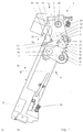
- Fig. 1 shows the coupling head 5 of a coupling device arranged locking mechanism 1 in a partially sectioned illustration.
- the locking mechanism 1 is used to secure two coupled coupling devices and consists essentially of a safety device in Shape of a bolt 2, an intermediate lever 3 and a release lever. 4 These three elements 2, 3, 4 together form a lever arrangement. Both the Latch 2 as well as the intermediate lever 3 and the release lever 4 are pivotable stored.
- the axis of rotation of the bolt 2 is denoted by the reference numeral 20, the one the intermediate lever 3 with the reference numeral 30 and that of the unlocking lever 4 provided with the reference numeral 40.
- the intermediate lever 3 is over a Spring 27 in the counterclockwise direction and the release lever 4 via a spring 46th loaded clockwise.
- the latch 2 has on the front side an actuating lug 21 and a locking projection 22, while in the back of a substantially concave Mold having recess 24 is recessed. This recess 24 goes in the intermediate lever 3 facing region 25 of the concave in a convex shape over.
- the bolt 2 also has a further recess 26th on, which serves to lock the bolt 2 in the rest position.
- the intermediate lever 3 has a roller 31, an extension 33 and one of a Projection 36 limited recess 35.
- the extension 33 is on one side provided with a convex end face 34.
- the unlocking lever 4 with a first cam 41 and a second cam 44 provided.
- the first cam 41 has a concave recess 42, which in the shape of the convex end face 34 of the intermediate lever. 3 corresponds.
- the second cam 44 has a tapered end face 45, which cooperate with the recess 35 and the projection 36th of the intermediate lever 3 is determined.
- the coupling head 5 itself has an oblique coupling surface on the coupling side 51, in which a recess 52 and a recess 53 is inserted.
- oblique means that the coupling surface 51 in the State of action of the coupling device an angle ⁇ with the longitudinal central axis. 6 of the rail vehicle to which the coupling device is attached is.
- the coupling surface 51 closes an angle ⁇ of approx. 67.5 ° with the longitudinal center axis 6 of the rail vehicle, when the coupling device is in the engaged state. By the size of this angle ⁇ can possibly take into account the respective requirements and environmental conditions be worn.
- the coupling surface 51 is on one side of a V-shaped coupling member 54 and on the opposite side of a corresponding recess 56 limited.
- the coupling member 54 with parallel to the coupling surface 51 extending side surfaces 55 and Recess 56 with parallel to the coupling surface 51 extending wall surfaces 57th Mistake.
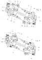
- FIG. 2 From Fig. 2 is a coupling device 7 in a side view and from the Fig. 3 in a plan view, wherein from the illustration according to FIG. 2 in particular the V-shaped configuration of the coupling member 54 is apparent.
- a coupling arrangement consists of two such coupling devices 7, which order 180 ° are arranged rotated about a vertical axis against each other. Because the principal Functioning of coupling arrangements for rail vehicles known is hereinafter referred to only in connection with the invention essential Parts received.
- the coupling head 5 of the coupling device 7 is via a damping device 8 is supported on a support arm 9.
- the support arm 9 is a storage 11th attached to the rail vehicle (not shown).
- the storage 11 of the support arm 9 is provided with a hinge plate 17, in each of which a recess on both sides 18, 19 is taken in.
- two spring-loaded, with rollers 13, 15 provided Levers 12, 14 are provided, the rollers 13, 15 in the recesses 18, 19th engage and the support arm 9 in the rest position in a predetermined position hold.
- the two recesses 18, 19 are asymmetrical in the hinge plate 17th let in, so that the support arm 5 in the rest position by about 2.5 ° relative to the Longitudinal axis 15 of the rail vehicle is deflected.
- the support arm 9 is in further provided with a hinge 10, by means of which, if necessary, folded and can be fixed to a locking arm 16.
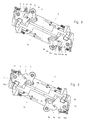
- Fig. 4 shows the initial state of the two for the coupling process in Arrow direction P1, P2 auffactzube Anlagenden coupling heads 5, 5a.
- the locking mechanism 1 is due to the bias of the two springs 27, 46 in the rest position, so that the locking projection 22 in the recess 53rd the coupling surface 51 is received and not on the coupling surface 51st protrudes.
- the relative shift the one opposite to the other coupling head 5, 5a is characterized by the pivotally supported support arms allows.
- the bolt 2 moves the locking projection 22 in the recess 52, 52 a and engages behind the respective coupling member 54, 54a.
- the intermediate lever 3, 3a is also released, so that this through the bias of the spring 27, 27a can rotate counterclockwise as far as until the roller 31, 31a in the corresponding with the latter, concave recess 24, 24a in the latch 2, 2a snaps into place (Fig. 7).
- the latch 2 is now through the intermediate lever 3 secured in his position. By the rotation of the intermediate lever.
- the latch 2a has only one Include the transverse component of the upcoming tensile force, whose size, together with the absolute magnitude of the tensile force, by the coefficient of friction between the side surfaces the coupling organs and the wall surfaces of the angle and the Side surfaces or the wall surfaces relative to the longitudinal center axis of the rail vehicle is determined.
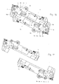
- Fig. 8 shows the beginning of the decoupling process.
- These are the two release levers 4, 4a rotated counter to the spring force counterclockwise.
- Around the release levers 4, to be able to rotate 4a, are both with an extension in Form of a square (not shown) on which a key, For example, the Switzerland conspiracyêtl, can be recognized.
- a key For example, the Switzerland conspiracyêtl, can be recognized.
- 4a When twisting the Entriegelungshebels 4, 4a in the counterclockwise direction are the first cam 41, 41 a the Intermediate lever 3, 3a free, while the second cam 44, 44a on the intermediate lever 3, 3a applies and this clockwise twisted until its Roller 31, 31a has rotated out of the recess 24, 24a and the intermediate lever 3, 3a releases the bolt 2, 2a.
- the release of the bolt 2, 2a is thereby allows or favors that the recess 24, 24a in the bolt 2, 2a in that of the roller 31, 31 a of the intermediate lever 3, 3 a facing region of a concave into a convex shape or into a straight line.
Landscapes
- Engineering & Computer Science (AREA)
- Mechanical Engineering (AREA)
- Lock And Its Accessories (AREA)
- Seats For Vehicles (AREA)
- Mechanical Operated Clutches (AREA)
- Fittings On The Vehicle Exterior For Carrying Loads, And Devices For Holding Or Mounting Articles (AREA)
Claims (16)
- Dispositif de couplage pourvu d'un mécanisme de verrouillage (1, 1a), plus particulièrement destiné aux véhicules ferroviaires, sachant que le dispositif de couplage comprend deux mécanismes de couplage (7) comportant chacun une tête de couplage (5, 5a), dans lesquels au moins la première tête de couplage (5, 5a) est pourvue d'un organe de couplage (54, 54a) et l'autre tête de couplage (5, 5a) respective est pourvue d'une encoche correspondante (56, 56a), et sachant que l'organe de couplage (54, 54a) respectif de la première tête de couplage (5, 5a) est prévu pour s'engager dans l'encoche (56, 56a) de l'autre tête de couplage (5, 5a) afin de réaliser le processus de couplage, et sachant que le mécanisme de verrouillage (1, 1a) présente un organe de sécurité formé comme un verrou (2, 2a) destiné à bloquer l'organe de couplage engagé (54, 54a), caractérisé en ce que le mécanisme de verrouillage (1, 1a) est conçu comme un dispositif de levier, dans lequel le verrou (2, 2a) est fonctionnellement relié à un levier de déverrouillage (4, 4a) par un levier intermédiaire (3, 3a), sachant que le levier de déverrouillage (4, 4a) permet le blocage direct ou indirect du verrou (2, 2a) en position de blocage ainsi que le déverrouillage du mécanisme de verrouillage (1, 1a), et sachant que le dispositif de levier est pourvu d'au moins un galet (31, 31a) et/ou une articulation permettant de réduire l'effort de commande, et que le verrou (2, 2a) est conçu de manière à pouvoir être amené mécaniquement, lors du processus de couplage, de la position de repos à la position de blocage par l'autre mécanisme de couplage respectif, et ramené en position de repos lors du processus de découplage, lorsque le levier de déverrouillage (4, 4a) est débrayé.
- Dispositif de couplage selon la revendication 1, caractérisé en ce qu'au moins le levier intermédiaire (3, 3a) et le levier de déverrouillage (4, 4a) sont pivotants.
- Dispositif de couplage selon les revendications 1 ou 2, caractérisé en ce que le levier intermédiaire (3, 3a) est pourvu d'au moins un galet (31, 31a) et/ou une articulation pour réduire l'effort de commande du levier de déverrouillage (4, 4a).
- Dispositif de couplage selon la revendication 1, caractérisé en ce que le levier intermédiaire (3, 3a) peut être amené de la position de fonctionnement à la position de repos par le verrou (2, 2a) lorsque le levier de déverrouillage (4, 4a) est débrayé.
- Dispositif de couplage selon l'une des revendications 2 à 4, caractérisé en ce que, lorsque le mécanisme de verrouillage (1, 1a) est embrayé, la transmission de force du verrou (2, 2a) au levier intermédiaire (3, 3a) s'exerce de manière sensiblement radiale par rapport à l'axe de rotation (30, 30a) du levier intermédiaire (3, 3a).
- Dispositif de couplage selon l'une quelconque des revendications précédentes, caractérisé en ce que, lorsque le mécanisme de verrouillage (1, 1a) est embrayé, la transmission de force du levier intermédiaire (3, 3a) au levier de déverrouillage (4, 4a) s'exerce de manière sensiblement radiale par rapport à l'axe de rotation (40, 40a) du levier de déverrouillage (4, 4a).
- Dispositif de couplage selon la revendication 6, caractérisé en ce que le levier de déverrouillage (4, 4a) présente une première came (41, 41a) délimitée par une face frontale de forme concave (42, 42a), et en ce que le levier intermédiaire (3, 3a) présente un appendice (33, 33a) délimité par une face frontale de forme convexe (34, 34a) correspondant à la face frontale de forme concave (42, 42a) de la première came (41, 41a), les deux faces frontales (34, 34a et 42, 42a) se rejoignant lorsque le verrou (2, 2a) est embrayé.
- Dispositif de couplage selon l'une des revendications 3 à 7, sachant que le levier intermédiaire (3, 3a) est pourvu d'un galet (31, 31a), caractérisé en ce que le verrou (2, 2a) présente une encoche (24, 24a) correspondant au galet (31, 31a), dans laquelle le galet (31, 31a) est prévu pour s'engager afin de bloquer le verrou (2, 2a), sachant que l'encoche (24, 24a) située dans la zone (25, 25a) tournée vers le galet (31, 31a) du levier intermédiaire (3, 3a) passe d'une forme concave à une forme convexe ou à une droite.
- Dispositif de couplage selon l'une quelconque des revendications précédentes, caractérisé en ce que le verrou (2, 2a) présente une encoche supplémentaire (26, 26a), laquelle est prévue pour fonctionner avec le galet (31, 31a) monté sur le levier intermédiaire (3, 3a) de telle sorte que le verrou (2, 2a) puisse être bloqué en position de repos.
- Dispositif de couplage selon l'une des revendications 2 à 9, caractérisé en ce que le levier intermédiaire (3, 3a) et le levier de déverrouillage (4, 4a) sont soumis à l'action d'un ressort, respectivement en direction du verrou (2, 2a) et du levier intermédiaire (3, 3a), de telle sorte que lorsque le verrou (2, 2a) est en position de blocage, le dispositif de levier se trouve dans une position de fonctionnement spécifique dans laquelle le verrou (2, 2a) est bloqué.
- Dispositif de couplage selon la revendication 10, caractérisé en ce que le levier intermédiaire (3, 3a) peut être amené par le verrou (2, 2a) à s'opposer à la tension du ressort.
- Dispositif de couplage selon la revendication 10 ou 11, caractérisé en ce que les éléments soumis à l'action d'un ressort (3, 3a, 4, 4a) peuvent basculer, par l'autre tête de couplage (5, 5a) respective, de la position de repos à la position de fonctionnement lors du processus de couplage.
- Dispositif de couplage selon l'une quelconque des revendications précédentes, caractérisé en ce que le verrou (2, 2a) est pourvu d'une saillie de verrouillage (22, 22a), laquelle est prévue pour bloquer l'organe de couplage (54, 54a) de l'autre tête de couplage (5, 5a) respective à l'état d'engagement.
- Dispositif de couplage selon l'une quelconque des revendications précédentes, caractérisé en ce que le verrou (2, 2a) présente un bec de commande (21, 21a) lequel s'étend, lors du processus de couplage, sur la plage de mouvement de l'organe de couplage (54, 54a) de l'autre tête de couplage (5, 5a) respective.
- Dispositif de couplage selon l'une quelconque des revendications précédentes, caractérisé en ce qu'un moyen permettant de faire basculer manuellement ou automatiquement ledit levier est prévu sur le levier de déverrouillage (4, 4a).
- Dispositif de couplage selon la revendication 15, caractérisé en ce que le levier de déverrouillage (4, 4a) est pourvu d'un appendice pouvant recevoir une clé permettant de faire basculer le levier de déverrouillage (4, 4a).
Applications Claiming Priority (2)
| Application Number | Priority Date | Filing Date | Title |
|---|---|---|---|
| DE19829393 | 1998-07-01 | ||
| DE19829393A DE19829393A1 (de) | 1998-07-01 | 1998-07-01 | Verriegelungsmechanismus für eine Kupplungsanordnung |
Publications (3)
| Publication Number | Publication Date |
|---|---|
| EP0972693A2 EP0972693A2 (fr) | 2000-01-19 |
| EP0972693A3 EP0972693A3 (fr) | 2000-10-25 |
| EP0972693B1 true EP0972693B1 (fr) | 2005-04-27 |
Family
ID=7872634
Family Applications (1)
| Application Number | Title | Priority Date | Filing Date |
|---|---|---|---|
| EP99810501A Expired - Lifetime EP0972693B1 (fr) | 1998-07-01 | 1999-06-08 | Mécanisme de verrouillage pour un dispositif d'accouplement |
Country Status (4)
| Country | Link |
|---|---|
| EP (1) | EP0972693B1 (fr) |
| AT (1) | ATE294088T1 (fr) |
| DE (2) | DE19829393A1 (fr) |
| ES (1) | ES2241252T3 (fr) |
Families Citing this family (4)
| Publication number | Priority date | Publication date | Assignee | Title |
|---|---|---|---|---|
| EP3750771B1 (fr) | 2019-06-14 | 2023-04-05 | Faiveley Transport Schwab AG | Accouplement doté d'un accouplement électrique, en particulier pour un véhicule ferroviaire |
| EP3750770B1 (fr) | 2019-06-14 | 2024-10-09 | Faiveley Transport Schwab AG | Accouplement, en particulier pour un véhicule ferroviaire |
| CH716316B1 (de) | 2019-06-14 | 2023-05-15 | Faiveley Transp Schwab Ag | Kupplungskopf, insbesondere für ein Schienenfahrzeug. |
| CN110422194B (zh) * | 2019-09-09 | 2024-03-08 | 中车青岛四方车辆研究所有限公司 | 折叠车钩和车辆 |
Family Cites Families (3)
| Publication number | Priority date | Publication date | Assignee | Title |
|---|---|---|---|---|
| DE554398C (de) | 1931-04-25 | 1932-07-07 | Heinrich Eichler | Selbsttaetige Doppelkupplung |
| DE3815953A1 (de) * | 1988-05-10 | 1989-11-23 | Bergische Stahlindustrie | Schnell-loesevorrichtung fuer kurzkupplungen |
| CH675864A5 (fr) * | 1988-05-18 | 1990-11-15 | Fischer Ag Georg |
-
1998
- 1998-07-01 DE DE19829393A patent/DE19829393A1/de not_active Ceased
-
1999
- 1999-06-08 AT AT99810501T patent/ATE294088T1/de not_active IP Right Cessation
- 1999-06-08 DE DE59911967T patent/DE59911967D1/de not_active Expired - Lifetime
- 1999-06-08 EP EP99810501A patent/EP0972693B1/fr not_active Expired - Lifetime
- 1999-06-08 ES ES99810501T patent/ES2241252T3/es not_active Expired - Lifetime
Also Published As
| Publication number | Publication date |
|---|---|
| EP0972693A2 (fr) | 2000-01-19 |
| ATE294088T1 (de) | 2005-05-15 |
| DE19829393A1 (de) | 2000-01-05 |
| ES2241252T3 (es) | 2005-10-16 |
| DE59911967D1 (de) | 2005-06-02 |
| EP0972693A3 (fr) | 2000-10-25 |
Similar Documents
| Publication | Publication Date | Title |
|---|---|---|
| DE3031122C2 (fr) | ||
| EP4330110B1 (fr) | Attelage automatique de traction et procédé de dételage d'un attelage automatique de traction | |
| EP1182062B2 (fr) | Attelage de remorque | |
| DE3901629C2 (de) | Aufsatteleinrichtung für Sattelschlepper | |
| DE69922373T2 (de) | Verschlussvorrichtung und haubenschloss für ein fahrzeug mit einer derartigen verschlussvorrichtung | |
| DE3035434C2 (fr) | ||
| EP3303091B1 (fr) | Dispositif de raccordement d'un arbre d'accouplement à une caisse d'un véhicule guidé | |
| EP3448733B1 (fr) | Ensemble support de palier | |
| DE2152613C3 (de) | Vorrichtung zum Sichern der Sperrklinke in einem Kraftfahrzeugtürverschluß | |
| DE1653994A1 (de) | Tuerschloss fuer Fahrzeuge | |
| EP0972693B1 (fr) | Mécanisme de verrouillage pour un dispositif d'accouplement | |
| DE2444021C3 (de) | Runge für Ladeplattformen von Fahrzeugen | |
| EP0578073B1 (fr) | Attelage de remorque | |
| DE102019106438A1 (de) | Aufstellbares Klappenscharnier | |
| WO2013117255A1 (fr) | Système de fermeture, notamment pour des chaînes de protection pour pneus | |
| DE3825593C1 (en) | Lock for doors or flaps of motor vehicles | |
| DE29808661U1 (de) | Sicherungsvorrichtung für mittels Tragseil hebbare Tore | |
| EP1782972B1 (fr) | Attelage de remorque pour un véhicule tracteur, notamment pour un tracteur agricole | |
| WO2020212070A1 (fr) | Dispositif d'ouverture d'élément en forme d'ailette, ainsi que véhicule | |
| EP0722031A1 (fr) | Dispositif de surveillance d'un ressort de torsion précontraint | |
| DE1264990B (de) | Tuerverschluss, insbesondere fuer Kraftwagen | |
| EP3782829B1 (fr) | Mécanisme de verrouillage pour un embrayage à bille | |
| DE10151382A1 (de) | Anhängevorrichtung | |
| DE3033395A1 (de) | Vorrichtung zum ver- und entriegeln eines kippbaren fahrzeug-fahrerhauses | |
| EP4201864A1 (fr) | Système d'entraînement |
Legal Events
| Date | Code | Title | Description |
|---|---|---|---|
| PUAI | Public reference made under article 153(3) epc to a published international application that has entered the european phase |
Free format text: ORIGINAL CODE: 0009012 |
|
| AK | Designated contracting states |
Kind code of ref document: A2 Designated state(s): AT BE CH DE DK ES FI FR GB IT LI NL SE |
|
| AX | Request for extension of the european patent |
Free format text: AL;LT;LV;MK;RO;SI |
|
| PUAL | Search report despatched |
Free format text: ORIGINAL CODE: 0009013 |
|
| AK | Designated contracting states |
Kind code of ref document: A3 Designated state(s): AT BE CH CY DE DK ES FI FR GB GR IE IT LI LU MC NL PT SE |
|
| AX | Request for extension of the european patent |
Free format text: AL;LT;LV;MK;RO;SI |
|
| 17P | Request for examination filed |
Effective date: 20001125 |
|
| AKX | Designation fees paid |
Free format text: AT BE CH DE DK ES FI FR GB IT LI NL SE |
|
| 17Q | First examination report despatched |
Effective date: 20030606 |
|
| GRAP | Despatch of communication of intention to grant a patent |
Free format text: ORIGINAL CODE: EPIDOSNIGR1 |
|
| GRAS | Grant fee paid |
Free format text: ORIGINAL CODE: EPIDOSNIGR3 |
|
| GRAA | (expected) grant |
Free format text: ORIGINAL CODE: 0009210 |
|
| AK | Designated contracting states |
Kind code of ref document: B1 Designated state(s): AT BE CH DE DK ES FI FR GB IT LI NL SE |
|
| PG25 | Lapsed in a contracting state [announced via postgrant information from national office to epo] |
Ref country code: NL Free format text: LAPSE BECAUSE OF FAILURE TO SUBMIT A TRANSLATION OF THE DESCRIPTION OR TO PAY THE FEE WITHIN THE PRESCRIBED TIME-LIMIT Effective date: 20050427 Ref country code: IT Free format text: LAPSE BECAUSE OF FAILURE TO SUBMIT A TRANSLATION OF THE DESCRIPTION OR TO PAY THE FEE WITHIN THE PRE;WARNING: LAPSES OF ITALIAN PATENTS WITH EFFECTIVE DATE BEFORE 2007 MAY HAVE OCCURRED AT ANY TIME BEFORE 2007. THE CORRECT EFFECTIVE DATE MAY BE DIFFERENT FROM THE ONE RECORDED.SCRIBED TIME-LIMIT Effective date: 20050427 Ref country code: GB Free format text: LAPSE BECAUSE OF FAILURE TO SUBMIT A TRANSLATION OF THE DESCRIPTION OR TO PAY THE FEE WITHIN THE PRESCRIBED TIME-LIMIT Effective date: 20050427 |
|
| REG | Reference to a national code |
Ref country code: GB Ref legal event code: FG4D Free format text: NOT ENGLISH |
|
| REG | Reference to a national code |
Ref country code: CH Ref legal event code: NV Representative=s name: ROTTMANN, ZIMMERMANN + PARTNER AG Ref country code: CH Ref legal event code: EP |
|
| REF | Corresponds to: |
Ref document number: 59911967 Country of ref document: DE Date of ref document: 20050602 Kind code of ref document: P |
|
| PG25 | Lapsed in a contracting state [announced via postgrant information from national office to epo] |
Ref country code: SE Free format text: LAPSE BECAUSE OF FAILURE TO SUBMIT A TRANSLATION OF THE DESCRIPTION OR TO PAY THE FEE WITHIN THE PRESCRIBED TIME-LIMIT Effective date: 20050727 Ref country code: DK Free format text: LAPSE BECAUSE OF FAILURE TO SUBMIT A TRANSLATION OF THE DESCRIPTION OR TO PAY THE FEE WITHIN THE PRESCRIBED TIME-LIMIT Effective date: 20050727 |
|
| REG | Reference to a national code |
Ref country code: ES Ref legal event code: FG2A Ref document number: 2241252 Country of ref document: ES Kind code of ref document: T3 |
|
| NLV1 | Nl: lapsed or annulled due to failure to fulfill the requirements of art. 29p and 29m of the patents act | ||
| GBV | Gb: ep patent (uk) treated as always having been void in accordance with gb section 77(7)/1977 [no translation filed] |
Effective date: 20050427 |
|
| ET | Fr: translation filed | ||
| PLBE | No opposition filed within time limit |
Free format text: ORIGINAL CODE: 0009261 |
|
| STAA | Information on the status of an ep patent application or granted ep patent |
Free format text: STATUS: NO OPPOSITION FILED WITHIN TIME LIMIT |
|
| 26N | No opposition filed |
Effective date: 20060130 |
|
| PGFP | Annual fee paid to national office [announced via postgrant information from national office to epo] |
Ref country code: AT Payment date: 20080515 Year of fee payment: 10 |
|
| REG | Reference to a national code |
Ref country code: CH Ref legal event code: NV Representative=s name: LUCHS & PARTNER PATENTANWAELTE |
|
| PG25 | Lapsed in a contracting state [announced via postgrant information from national office to epo] |
Ref country code: AT Free format text: LAPSE BECAUSE OF NON-PAYMENT OF DUE FEES Effective date: 20090608 |
|
| REG | Reference to a national code |
Ref country code: FR Ref legal event code: PLFP Year of fee payment: 18 |
|
| REG | Reference to a national code |
Ref country code: FR Ref legal event code: PLFP Year of fee payment: 19 |
|
| REG | Reference to a national code |
Ref country code: FR Ref legal event code: PLFP Year of fee payment: 20 |
|
| PGFP | Annual fee paid to national office [announced via postgrant information from national office to epo] |
Ref country code: CH Payment date: 20180614 Year of fee payment: 20 Ref country code: DE Payment date: 20180530 Year of fee payment: 20 Ref country code: FI Payment date: 20180612 Year of fee payment: 20 |
|
| PGFP | Annual fee paid to national office [announced via postgrant information from national office to epo] |
Ref country code: FR Payment date: 20180511 Year of fee payment: 20 Ref country code: BE Payment date: 20180417 Year of fee payment: 20 |
|
| PGFP | Annual fee paid to national office [announced via postgrant information from national office to epo] |
Ref country code: ES Payment date: 20180702 Year of fee payment: 20 |
|
| REG | Reference to a national code |
Ref country code: DE Ref legal event code: R071 Ref document number: 59911967 Country of ref document: DE |
|
| REG | Reference to a national code |
Ref country code: CH Ref legal event code: PL |
|
| REG | Reference to a national code |
Ref country code: BE Ref legal event code: MK Effective date: 20190608 |
|
| REG | Reference to a national code |
Ref country code: ES Ref legal event code: FD2A Effective date: 20201201 |
|
| PG25 | Lapsed in a contracting state [announced via postgrant information from national office to epo] |
Ref country code: ES Free format text: LAPSE BECAUSE OF EXPIRATION OF PROTECTION Effective date: 20190609 |