EP0972697A2 - Palier avant pour la cabine basculante d'un camion - Google Patents
Palier avant pour la cabine basculante d'un camion Download PDFInfo
- Publication number
- EP0972697A2 EP0972697A2 EP99111005A EP99111005A EP0972697A2 EP 0972697 A2 EP0972697 A2 EP 0972697A2 EP 99111005 A EP99111005 A EP 99111005A EP 99111005 A EP99111005 A EP 99111005A EP 0972697 A2 EP0972697 A2 EP 0972697A2
- Authority
- EP
- European Patent Office
- Prior art keywords
- bearing
- cab
- connection
- stabilizer
- arm
- Prior art date
- Legal status (The legal status is an assumption and is not a legal conclusion. Google has not performed a legal analysis and makes no representation as to the accuracy of the status listed.)
- Granted
Links
Images










Classifications
-
- B—PERFORMING OPERATIONS; TRANSPORTING
- B62—LAND VEHICLES FOR TRAVELLING OTHERWISE THAN ON RAILS
- B62D—MOTOR VEHICLES; TRAILERS
- B62D33/00—Superstructures for load-carrying vehicles
- B62D33/06—Drivers' cabs
- B62D33/063—Drivers' cabs movable from one position into at least one other position, e.g. tiltable, pivotable about a vertical axis, displaceable from one side of the vehicle to the other
- B62D33/067—Drivers' cabs movable from one position into at least one other position, e.g. tiltable, pivotable about a vertical axis, displaceable from one side of the vehicle to the other tiltable
Definitions
- the invention relates to a front mounting of the tilting cab Truck.
- cab storage In the cab storage according to DE 196 12 502 A1 is the tiltable cab in front by means of two spring-damper legs opposite the chassis frame cushioned, each of which is attached to a frame bracket and is articulated at the top of an end region of a cross stabilizer bar.
- the latter forms here the front bearing element for the cab and at the same time the Swivel axis for tipping it, with the cab over the front end a bracket attached to it pivotally articulated on the anti-roll bar is.
- the position of the cab and the spring-damper legs is opposite the chassis frame via the anti-roll bar through two trailing arms stabilized, each with its front end the cross stabilizer bar axially secured and with its rear end via an integrated bearing transversely and longitudinally guided and pivoted in a frame-fixed bearing bracket is.
- cab storage In the cab storage according to DE 44 13 414 A1 is the tiltable cab at the front also by means of two spring-damper legs opposite the chassis frame cushioned, each of which is attached to a frame-fixed bearing block and is articulated on a one-piece, U-shaped stabilizer link.
- This Stabilizer handlebar consists of a left and right spring leaf handlebar, the front are connected by a cross strut and each of which is fixed at the rear is attached to a chassis frame.
- the cab itself is over two Consoles hinged to the U-shaped stabilizer bar, each in one Bearing bracket located on the top of the anti-roll bar at the transition area between one Spring leaf link and the cross strut is attached. Obviously this is cab storage seen relatively longitudinally in the vehicle longitudinal direction, which the No longer meets the demands of modern driver cabin bearings.
- the two of the truck are part of its chassis frame Frame side members labeled 1 and 2. At the front end of each one is the same a multifunction bearing plate 3, 4 attached. These front multi-function end shields 3, 4 serve to accommodate a large number of vehicle parts, including those which are attributable to the front mounting of the cab 5.
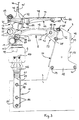
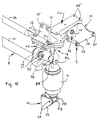
- the front cab mounting includes the following components, namely two spring-damper legs 6, 7, a U-shaped stabilizer arm 8, two seen from above rear bearing blocks 9, 10, two spring-damper leg holders 11, 12 and two front Connection brackets 13, 14.
- the left-hand components of the cab mounting are based on the vehicle's longitudinal axis, mirror-symmetrical to the right-hand side Components trained and arranged.
- the U-shaped stabilizer arm 8 consists of a right longitudinal arm 15, a left longitudinal arm 16, a cross bar connecting these at the front 17 and two, each above the transition area between crossbar 17th and a longitudinal arm 15, 16 arranged bearing eyes 18, 19.
- bearing eyes 18, 19 bearings 20, 21 are installed, their axes of rotation in a horizontal Transverse line 22 are aligned.
- each of the two Longitudinal arms 15, 16 of the stabilizer rocker 8 also have a bearing eye 23, 24 provided with built-in bearing 25, 26, the axes of rotation of which are also in one horizontal cross line 27 aligned with each other, which runs parallel to the cross line 22.
- the U-shaped stabilizer rocker 8 can either be a one-piece drop forge Steel casting realized or alternatively from three prefabricated Individual parts.
- the two longitudinal arms 15, 16 including all bearing eyes and other parts either through a drop forged or steel casting and the crossbar 17 either through one Pipe or a full-material drop forged part can be formed. To These three parts are then machined accordingly welded together.
- the longitudinal arms 15, 16 of the stabilizer rocker 8 are shaped and arranged in this way that they are aimed in the longitudinal direction in a frontal crash of the truck are deformable and at the same time have an energy-absorbing effect.
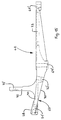
- the longitudinal arms 15, 16 of the stabilizer rocker 8 between the front and rear end - viewed from the side - slightly bent upwards and - viewed from above - odd, for example S-shaped or Z-shaped, what defines deformable folding, bending or in a frontal crash Kink zones means.
- the two longitudinal arms 15, 16 are preferably inside the U-shaped stabilizer rocker 8 swept to each other in the sense that their rear ends 23, 24 are less spaced apart than theirs front ends 18, 19.
- the U-shaped stabilizer arm 8 is on the rear of the longitudinal arms 15, 16th arranged bearing eyes 23, 24 and the built-in bearings 25, 26 longitudinal and guided across and about the axis of rotation - line 27 - pivotable on the two Bearing blocks 9, 10 articulated. Each of them is at the back of one of the two multi-function end shields 3, 4 releasably attached, namely at its lower End region 28 by two screw connections 29, 30, one of which (29) entirely front and the other (30) is arranged at the very rear.
- each rear Bearing block 9, 10 above this fastening zone 28, but below the connection level for the stabilizer arm 8 in the event of a frontal crash of the truck defines deformable fold or crease zone by constructive measures such as cross-sectional reductions, material weakening, indentations, constrictions or the like can be realized.
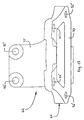
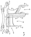
- each bearing block 9, 10 is composed of two parts, a defined deformable main part 31 and one flanged to the front thereof fastened by means of screw connections 32, on which a Longitudinal arm 15 or 16 of the stabilizer rocker 8 on the rear end Bearing eye and the bearing built into it are guided crossways and across one Bearing axis or screw 40 is longitudinally guided and pivoted.
- Both the main part 31 and the connecting part 33 of a bearing block 9, 10 are preferably realized by a sheet metal part.
- the connecting part 33 of each bearing block 9, 10 in Seen from above, bent in a U-shape and in detail has a flat rear Connection plate 34 with several screw through holes 35 and on both sides arranged on the connecting plate 34 vertically forward and parallel to each other angled side walls 36, 37 with mutually aligned bores 38, 39 for passing through a bearing axis or bearing screw 40.
- the main part 31 of a bearing block 9, 10 has a bent sheet metal part a flat and slightly backward inclined front connection plate 41 with several Screw feed-through holes 42 for front flanging and fastening of the connecting part 33 by means of a corresponding number of screw connections 43 on.
- On the front connection plate 41 close on both sides angled backwards, parallel to each other 44, 45 on, in the lower region screw feed-through holes 46, 47 for the two screw connections 29, 30 are formed.
- the associated screw through holes in the respective multifunction bearing plate are 46 'and 47' designated.
- the two side cheeks 44, 45 of the main part 31 of a bearing block 9, 10 by a distance ensuring their distance, not in the deformation zone arranged crossbar 48 connected to each other.
- 23 is the crossbar 48 by a rear end on a side cheek 44 or 45 angled towards the opposite side wall 45 or 44 and is formed on this cross beam 49 welded on in a supporting manner. in the In contrast to the example according to FIGS.
- the crossbeam 48 is in the front area of the main part 31 of each bearing block 9, 10, but spatially arranged behind the front screw connection 29 and for example by a Angle section piece 50 (as shown), a bolt or a piece of pipe realized, that extends between the two side cheeks 44, 45 welded to them is.
- the cross-member 50 serves as a stop, which in the event of a frontal crash of the truck with deformation of the rear bracket 9, 10 rotatory around the front screw connection 29 on the top 51 of the bearing block 9 or 10 accommodating multi-function end shield 3 or 4 limiting comes to the plant.
- the cab 5 is at the front with its base 66 on the two connection brackets 13, 14 attached, articulated with these on the two spring-damper legs 6, 7 and cushioned over this relative to the chassis frame 1, 2.
- the spring-damper legs 6, 7 on the chassis frame are the two spring-damper leg holders 11, 12 provided. Each of them is laterally the same in the outside Elevation on a multifunction bearing plate 3 or 4 can be detached using screw holes 56 'passing through screw connections 56 and takes between two side cheeks 57, 58 cross-guided and pivoted at the bottom End of a spring-damper leg 6 or 7 arranged bearing eye 59 with built-in Camp 60 on.
- a bearing axis that runs transversely in the longitudinal direction of the vehicle 61 provides the connection between the bearing 60 and the spring-damper leg holder 11 or 12 ago and forms the pivot axis for the thus articulated spring-damper leg 6 and 7.
- the upper end of each spring-damper leg 6, 7 is taken in a connection console 13 or 14.
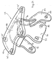
- Each of the two connection brackets 13, 14 is composed of two parts, namely an upper support member 62 on which the cab 5 is fixed, and one lower bearing part 63, on which a spring-damper leg 6 or 7 and another Place the stabilizer rocker 8 with one of the two bearing eyes arranged on it 18, 19 are hinged with built-in bearings 20, 21.
- each connection bracket 13, 14 is a large area Plate formed with its rear section 73 via several vertical screw connections 64, 65 is attached to the cab floor 66 and with a front section 74 protrudes a certain amount from the front of the cab floor 66 and one forms oblique support ramp 67.
- each connector bracket support 62 is in the rear section 73 formed flat and pulled up obliquely upwards in the front section 74, at its front section 68, the crossbar 69 is supported and is attached.
- the thickness of the support plate increases from the back to about In the middle of its longitudinal extension wedge-shaped to a maximum and then from this thickest cross-sectional point back to a certain point up to the front end Dimension, whereby this last-mentioned area forms the support ramp 67.
- each connection bracket 13, 14 has at the transition between flat Plate area and sloping support ramp area protruding upwards Fastening flange 75 on which the cab floor 66 with a raised Front edge 76 connected to the stop and by means of several horizontal screw connections 77 is attached.
- the associated screw holes are 77 ' designated.
- the rear cab floor area 78 is on the flat top of the rear portion 73 of the connector bracket support 62 supported and clamped there by means of the vertical screw connections 64, 65, the front vertical screw connections 64 in the area of the largest Panel thickness and the vertical screw connections 65 at the rear panel end area are arranged.
- the associated screw holes are labeled 64 'and 65'.
- each connection bracket 13, 14 has an end plate 79 at the top flat top 80 with which it is on the flat bottom 70 of the support ramp 67 flanged a connection bracket support part 62 and there by means of the vertical screw connections 71, 72 is clamped.
- the associated screw holes in the Plates 67 and 79 are labeled 71 'and 72', respectively.
- connection bracket support part 62 The front vertical screw connections 71, with which the bearing part 63 of each connection bracket 13, 14 with its end plate 79 on the support ramp 67 of a connection bracket support part 62 is clamped, are preferably also for attachment the crossbar 69 pulled in front on the upper part 74 of the supporting part.
- each connection bracket 13, 14 has, in addition to the end plate 79 first outer mouth 81 spaced downward therefrom and a second, further up, but also from the end plate 79 downwardly spaced interior Mouth 82 on.
- the outer mouth 81 is to the side of walls 83, 84 with these penetrating, horizontally transversely aligned bores 85, 86 are limited and used for the side Recording and storage of the from a bearing eye 87 with built-in Bearing 88 existing upper end of a spring-damper leg 6 and 7 respectively by means of a transverse bearing axis 89 on the bearing part 63 of a connection bracket 13, 14.
- each connection bracket bearing part 63 is also laterally through walls 90, 91 with these penetrating, horizontally across aligned holes 92, 93 limited and is used for side-guided recording and storage of a bearing eye arranged at the front on the stabilizer arm 8 18 and 19 together with bearings 20 and 21 installed therein by means of a transverse one Bearing axis 94 or 95 on the bearing part 63 of a connection bracket 13, 14.
- the inner boundary wall 84 is the first outer Mouth 81 and the outer boundary wall 90 of the second inner mouth 82 formed by a single common partition. All mouth-limiting Walls 83, 84, 90, 91 are supported on the underside of the upper end plate 79 connected.
- each connection console 13, 14 can either by a Steel casting or by a welded structure made of several welded together Steel sheets can be realized.
- the outer boundary wall 83 of the outer mouth 81 bent towards the inner boundary wall 84, welded there and also through a vertical rib 96 to the face plate 79 supported.
- each connection bracket 13, 14 is preferably by a Ductile iron part realized.
- the front vertical screw connections 71 with which the bearing part 63 of each connection bracket 13, 14 with its upper end plate 79 on the support ramp 67 Connection bracket support member 62 is clamped, are preferably on such Limit load designed that if in the event of a frontal crash of the truck different deformation zones in the cab bearing elements 9, 10, 15, 16 to are deformed to their predetermined limits, said front vertical screw connections 71 tear off, the adjacent rear vertical screw connections 72 but only be stretched and each connection bracket bearing part 63 then rotates can move around these rear vertical screw connections 72, whereby an axial offset of the spring-damper-leg and stabilizer rocker articulation points 81, 82, spaced downward from the end plate 63, results in the rear.
- the front cab mounting also has a compression of the cab device limiting when tipping.
- This consists of two of equal length Stop feet 97, 98, each of which protrudes below at the front end, respectively a longitudinal arm 15, 16 of the U-shaped stabilizer arm 8 is arranged, and two associated stops 99, 100 arranged fixed to the frame.
- the stop 99 or 100 by an interchangeable Stop plate formed on a raised, by a Cross bar formed upper end of a spring damper leg holder 11 and 12 respectively is optionally attached elastically resilient or cushioned, the stop plate load-bearing bracket cross bar and the raised bracket wall by a stiffening ribs 101 and 102 welded to them are supported.
- FIG. 3 shows the cab in the untilted position and the stop feet 97, 98 in such a distance from the associated stops 99 and 100 that the normal compression of the cab 5 is not hindered while driving.
- Fig. 4 shows the cab 5 in the maximum tilted position in which the stop feet Sit 97 or 98 on the stops 99 or 100 and so on Compression of the spring-damper legs 6, 7 hinder.
- the stop feet 97, 98 describe a rotational movement about the axis of rotation 27, which is caused by the rear-end bearing screw connections 40 the U-shaped stabilizer rocker 8 with the bearing blocks 9, 10 goes.
- the stop 99, 100 is not on the spring damper leg holder 11 or 12, but on its own holder 103 or 104 arranged, which in turn on one of the two multi-function end shields 3 or 4 is attached and other, not of interest here Serves purposes.
- the location, design and type of attachment of the stop plates are same as in the aforementioned case.
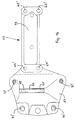
- the stop feet 97, 98 are preferably each in one piece with the longitudinal arms 15, 16 of the U-shaped stabilizer rocker 8 and rear - like 12 - through a strut 105 to the respective longitudinal arm 15 or 16 stiffened.
- the respective stop foot 97 or 98 goes down on one longitudinal-arm-front receiving eye 106, 107, in the inside blind bore the associated end of the cross bar 17 form and optionally also inserted force-fit and then welded.
- Comfort is achieved through long spring travel. Since the rear bearing of the stabilizer arm on the frame side in one If the "quiet" area of the chassis frame is arranged, there is also an improvement in the cross shake. The separation of the comfort bearings from the pivot bearing for tipping ensures optimal design.
- the cost reduction is achieved in that compared to previous cab bearings different parts are omitted.
- the freedom from tension is achieved in that compensation options between Stabilizer arm and chassis frame on the one hand and cab on the other given are.
- crash optimization takes place through energy-consuming design and / or Arrangement of different storage parts. Here are a few comments.
- the rear pillow blocks 9, 10 experience a certain stress level locally strong deformations in the intended places, whereby a shift of the rear stabilizer arm bearings to the rear and done below. Depending on the size of those acting on the cab from the front Force can then even roll over the stabilizer rocker 8 to the rear. Because of this effect brought about by targeted component design, in the event of a crash, the largest possible displacement of the cab towards the rear achieve the chassis as a combination of the arc movement of the stabilizer swing bearing points around a deep axis of rotation and double Stabilizer arm length from the stabilizer arm rollover movement. A firm connection remains during this entire movement preserved between the cab and the chassis.
- the rear bearing blocks 9, 10 build relatively high, the height of which, for. B. double the length in the lower area Connection zone 28 is. This favors because of that in the area of the upper end each bracket 9, 10 lying connection point 40 of the stabilizer rocker 8 the deformation of the bearing blocks 9, 10 in the structurally predetermined areas.
Landscapes
- Engineering & Computer Science (AREA)
- Chemical & Material Sciences (AREA)
- Combustion & Propulsion (AREA)
- Transportation (AREA)
- Mechanical Engineering (AREA)
- Body Structure For Vehicles (AREA)
Applications Claiming Priority (2)
| Application Number | Priority Date | Filing Date | Title |
|---|---|---|---|
| DE19831314A DE19831314A1 (de) | 1998-07-13 | 1998-07-13 | Vordere Lagerung des kippbaren Fahrerhauses eines Lastkraftwagens |
| DE19831314 | 1998-07-13 |
Publications (3)
| Publication Number | Publication Date |
|---|---|
| EP0972697A2 true EP0972697A2 (fr) | 2000-01-19 |
| EP0972697A3 EP0972697A3 (fr) | 2002-11-20 |
| EP0972697B1 EP0972697B1 (fr) | 2005-08-10 |
Family
ID=7873872
Family Applications (1)
| Application Number | Title | Priority Date | Filing Date |
|---|---|---|---|
| EP99111005A Expired - Lifetime EP0972697B1 (fr) | 1998-07-13 | 1999-06-10 | Palier avant pour la cabine basculante d'un camion |
Country Status (2)
| Country | Link |
|---|---|
| EP (1) | EP0972697B1 (fr) |
| DE (2) | DE19831314A1 (fr) |
Cited By (1)
| Publication number | Priority date | Publication date | Assignee | Title |
|---|---|---|---|---|
| EP1013539A3 (fr) * | 1998-12-23 | 2002-11-20 | CARL DAN. PEDDINGHAUS GMBH & CO. KG | Dispositif de support de cabines sur véhicules utilitaires |
Families Citing this family (1)
| Publication number | Priority date | Publication date | Assignee | Title |
|---|---|---|---|---|
| DE10221346C1 (de) | 2002-05-14 | 2003-10-09 | Daimler Chrysler Ag | Anbindung für ein Fahrerhaus |
Citations (2)
| Publication number | Priority date | Publication date | Assignee | Title |
|---|---|---|---|---|
| DE4413414A1 (de) | 1994-04-18 | 1995-10-19 | Daimler Benz Ag | Anordnung zur Befestigung von Schwenklagern für Fahrerhäuser von Lastkraftwagen |
| DE19612502A1 (de) | 1996-03-29 | 1997-10-02 | Man Nutzfahrzeuge Ag | Vordere Lagerung des kippbaren Fahrerhauses eines Lastkraftwagen |
Family Cites Families (6)
| Publication number | Priority date | Publication date | Assignee | Title |
|---|---|---|---|---|
| US3948341A (en) * | 1974-12-23 | 1976-04-06 | Ford Motor Company | Tilt cab truck |
| GB8606398D0 (en) * | 1986-03-14 | 1986-04-23 | Erf Ltd | Suspension arrangements |
| SE468315B (sv) * | 1991-05-03 | 1992-12-14 | Volvo Ab | Anslagsstopp foer saavael oevre som nedre aendlaege hos en fordonshytt |
| AT403365B (de) * | 1993-04-19 | 1998-01-26 | Steyr Nutzfahrzeuge | Vordere lageranordnung für das fahrerhaus eines lastkraftwagens |
| DE19537722A1 (de) * | 1995-10-10 | 1997-04-17 | Man Nutzfahrzeuge Ag | Vordere Lagerung für das kippbare Fahrerhaus eines Frontlenker-Lastkraftwagen |
| GB9719577D0 (en) * | 1997-09-16 | 1997-11-19 | Hendrickson Europ Limited | Suspension systems |
-
1998
- 1998-07-13 DE DE19831314A patent/DE19831314A1/de not_active Withdrawn
-
1999
- 1999-06-10 DE DE59912381T patent/DE59912381D1/de not_active Expired - Lifetime
- 1999-06-10 EP EP99111005A patent/EP0972697B1/fr not_active Expired - Lifetime
Patent Citations (2)
| Publication number | Priority date | Publication date | Assignee | Title |
|---|---|---|---|---|
| DE4413414A1 (de) | 1994-04-18 | 1995-10-19 | Daimler Benz Ag | Anordnung zur Befestigung von Schwenklagern für Fahrerhäuser von Lastkraftwagen |
| DE19612502A1 (de) | 1996-03-29 | 1997-10-02 | Man Nutzfahrzeuge Ag | Vordere Lagerung des kippbaren Fahrerhauses eines Lastkraftwagen |
Cited By (1)
| Publication number | Priority date | Publication date | Assignee | Title |
|---|---|---|---|---|
| EP1013539A3 (fr) * | 1998-12-23 | 2002-11-20 | CARL DAN. PEDDINGHAUS GMBH & CO. KG | Dispositif de support de cabines sur véhicules utilitaires |
Also Published As
| Publication number | Publication date |
|---|---|
| EP0972697B1 (fr) | 2005-08-10 |
| EP0972697A3 (fr) | 2002-11-20 |
| DE19831314A1 (de) | 2000-01-20 |
| DE59912381D1 (de) | 2005-09-15 |
Similar Documents
| Publication | Publication Date | Title |
|---|---|---|
| EP0972700B1 (fr) | Palier avant pour la cabine basculante d'un camion | |
| EP0940272B1 (fr) | Chassis pour un camion à cabine avancée | |
| DE69931983T2 (de) | Stabilisator | |
| EP0798198B1 (fr) | Palier avant pour la cabine basculante d'un camion | |
| AT518405B1 (de) | Fahrerhauslagerung für ein kippbares Fahrerhaus eines Nutzfahrzeugs | |
| DE602004013204T2 (de) | Anordnung für fahrzeugkabinen | |
| EP0940320B1 (fr) | Chassis pour véhicule utilitaire lourd | |
| EP0972698B1 (fr) | Palier avant pour la cabine basculante d'un camion | |
| DE102004063936A1 (de) | Nutzfahrzeug, insbesondere Müllsammel- oder sonstiges Kommunalfahrzeug, mit einem Low-Entry-Fahrerhaus | |
| EP1306290B1 (fr) | Structure avant de véhicule | |
| EP0972699B1 (fr) | Palier avant pour la cabine basculante d'un camion | |
| DE69426991T2 (de) | Längsarmaufhängung | |
| DE102004041165A1 (de) | Fahrzeugkarosseriestruktur | |
| DE19961670C2 (de) | Hintere Lagerung des kippbaren Fahrerhauses eines Frontlenker-Lastkraftwagens | |
| EP0940319A2 (fr) | Chassis d'un véhicule utilitaire lourd | |
| DE60113932T2 (de) | Stossenergieabsorbierende Struktur für ein Kraftfahrzeug | |
| DE102004045157A1 (de) | Nutzfahrzeug, insbesondere Müllsammel- oder sonstiges Kommunalfahrzeug, mit einem Low-Entry-Fahrerhaus | |
| EP0972696B1 (fr) | Palier avant pour la cabine basculante d'un camion | |
| EP0972697B1 (fr) | Palier avant pour la cabine basculante d'un camion | |
| EP0940322B1 (fr) | Chassis pour véhicule utilitaire lourd | |
| DE102005014401B4 (de) | Lagerung eines kippbaren Fahrerhauses | |
| EP0940324A1 (fr) | Chassis pour véhicule utilitaire lourd | |
| EP0940325A1 (fr) | Chassis pour véhicule utilitaire lourd | |
| EP0940323A1 (fr) | Chassis pour véhicule utilitaire lourd | |
| DE10306381B4 (de) | Deformierbarer Vorderbau eines Kraftfahrzeuges |
Legal Events
| Date | Code | Title | Description |
|---|---|---|---|
| PUAI | Public reference made under article 153(3) epc to a published international application that has entered the european phase |
Free format text: ORIGINAL CODE: 0009012 |
|
| AK | Designated contracting states |
Kind code of ref document: A2 Designated state(s): AT BE CH CY DE DK ES FI FR GB GR IE IT LI LU MC NL PT SE |
|
| AX | Request for extension of the european patent |
Free format text: AL;LT;LV;MK;RO;SI |
|
| PUAL | Search report despatched |
Free format text: ORIGINAL CODE: 0009013 |
|
| AK | Designated contracting states |
Kind code of ref document: A3 Designated state(s): AT BE CH CY DE DK ES FI FR GB GR IE IT LI LU MC NL PT SE |
|
| AX | Request for extension of the european patent |
Free format text: AL;LT;LV;MK;RO;SI |
|
| 17P | Request for examination filed |
Effective date: 20021030 |
|
| 17Q | First examination report despatched |
Effective date: 20030109 |
|
| GRAH | Despatch of communication of intention to grant a patent |
Free format text: ORIGINAL CODE: EPIDOS IGRA |
|
| GRAS | Grant fee paid |
Free format text: ORIGINAL CODE: EPIDOSNIGR3 |
|
| AKX | Designation fees paid |
Designated state(s): DE FR IT NL SE |
|
| GRAA | (expected) grant |
Free format text: ORIGINAL CODE: 0009210 |
|
| AK | Designated contracting states |
Kind code of ref document: B1 Designated state(s): DE FR IT NL SE |
|
| REF | Corresponds to: |
Ref document number: 59912381 Country of ref document: DE Date of ref document: 20050915 Kind code of ref document: P |
|
| REG | Reference to a national code |
Ref country code: SE Ref legal event code: TRGR |
|
| ET | Fr: translation filed | ||
| PLBE | No opposition filed within time limit |
Free format text: ORIGINAL CODE: 0009261 |
|
| STAA | Information on the status of an ep patent application or granted ep patent |
Free format text: STATUS: NO OPPOSITION FILED WITHIN TIME LIMIT |
|
| 26N | No opposition filed |
Effective date: 20060511 |
|
| REG | Reference to a national code |
Ref country code: NL Ref legal event code: TD Effective date: 20110420 |
|
| REG | Reference to a national code |
Ref country code: FR Ref legal event code: CD |
|
| REG | Reference to a national code |
Ref country code: DE Ref legal event code: R081 Ref document number: 59912381 Country of ref document: DE Owner name: MAN TRUCK BUS AG, DE Free format text: FORMER OWNER: MAN NUTZFAHRZEUGE AG, 80995 MUENCHEN, DE Effective date: 20110518 Ref country code: DE Ref legal event code: R081 Ref document number: 59912381 Country of ref document: DE Owner name: MAN TRUCK & BUS AG, DE Free format text: FORMER OWNER: MAN NUTZFAHRZEUGE AG, 80995 MUENCHEN, DE Effective date: 20110518 |
|
| REG | Reference to a national code |
Ref country code: FR Ref legal event code: PLFP Year of fee payment: 18 |
|
| REG | Reference to a national code |
Ref country code: FR Ref legal event code: PLFP Year of fee payment: 19 |
|
| REG | Reference to a national code |
Ref country code: FR Ref legal event code: PLFP Year of fee payment: 20 |
|
| PGFP | Annual fee paid to national office [announced via postgrant information from national office to epo] |
Ref country code: NL Payment date: 20180625 Year of fee payment: 20 |
|
| PGFP | Annual fee paid to national office [announced via postgrant information from national office to epo] |
Ref country code: FR Payment date: 20180629 Year of fee payment: 20 |
|
| PGFP | Annual fee paid to national office [announced via postgrant information from national office to epo] |
Ref country code: SE Payment date: 20180627 Year of fee payment: 20 |
|
| PGFP | Annual fee paid to national office [announced via postgrant information from national office to epo] |
Ref country code: DE Payment date: 20180831 Year of fee payment: 20 Ref country code: IT Payment date: 20180622 Year of fee payment: 20 |
|
| REG | Reference to a national code |
Ref country code: DE Ref legal event code: R071 Ref document number: 59912381 Country of ref document: DE |
|
| REG | Reference to a national code |
Ref country code: NL Ref legal event code: MK Effective date: 20190609 |
|
| REG | Reference to a national code |
Ref country code: SE Ref legal event code: EUG |