EP0972816A2 - Phosphores polycristallins à rendement élevé et méthode de fabrication - Google Patents
Phosphores polycristallins à rendement élevé et méthode de fabrication Download PDFInfo
- Publication number
- EP0972816A2 EP0972816A2 EP99113410A EP99113410A EP0972816A2 EP 0972816 A2 EP0972816 A2 EP 0972816A2 EP 99113410 A EP99113410 A EP 99113410A EP 99113410 A EP99113410 A EP 99113410A EP 0972816 A2 EP0972816 A2 EP 0972816A2
- Authority
- EP
- European Patent Office
- Prior art keywords
- phosphor
- dopant
- host material
- host
- rare earth
- Prior art date
- Legal status (The legal status is an assumption and is not a legal conclusion. Google has not performed a legal analysis and makes no representation as to the accuracy of the status listed.)
- Granted
Links
Images

Classifications
-
- C—CHEMISTRY; METALLURGY
- C09—DYES; PAINTS; POLISHES; NATURAL RESINS; ADHESIVES; COMPOSITIONS NOT OTHERWISE PROVIDED FOR; APPLICATIONS OF MATERIALS NOT OTHERWISE PROVIDED FOR
- C09K—MATERIALS FOR MISCELLANEOUS APPLICATIONS, NOT PROVIDED FOR ELSEWHERE
- C09K11/00—Luminescent materials, e.g. electroluminescent or chemiluminescent
- C09K11/08—Luminescent materials, e.g. electroluminescent or chemiluminescent containing inorganic luminescent materials
- C09K11/88—Luminescent materials, e.g. electroluminescent or chemiluminescent containing inorganic luminescent materials containing selenium, tellurium or unspecified chalcogen elements
- C09K11/881—Chalcogenides
- C09K11/886—Chalcogenides with rare earth metals
-
- C—CHEMISTRY; METALLURGY
- C09—DYES; PAINTS; POLISHES; NATURAL RESINS; ADHESIVES; COMPOSITIONS NOT OTHERWISE PROVIDED FOR; APPLICATIONS OF MATERIALS NOT OTHERWISE PROVIDED FOR
- C09K—MATERIALS FOR MISCELLANEOUS APPLICATIONS, NOT PROVIDED FOR ELSEWHERE
- C09K11/00—Luminescent materials, e.g. electroluminescent or chemiluminescent
- C09K11/08—Luminescent materials, e.g. electroluminescent or chemiluminescent containing inorganic luminescent materials
- C09K11/77—Luminescent materials, e.g. electroluminescent or chemiluminescent containing inorganic luminescent materials containing rare earth metals
- C09K11/7701—Chalogenides
-
- C—CHEMISTRY; METALLURGY
- C09—DYES; PAINTS; POLISHES; NATURAL RESINS; ADHESIVES; COMPOSITIONS NOT OTHERWISE PROVIDED FOR; APPLICATIONS OF MATERIALS NOT OTHERWISE PROVIDED FOR
- C09K—MATERIALS FOR MISCELLANEOUS APPLICATIONS, NOT PROVIDED FOR ELSEWHERE
- C09K11/00—Luminescent materials, e.g. electroluminescent or chemiluminescent
- C09K11/08—Luminescent materials, e.g. electroluminescent or chemiluminescent containing inorganic luminescent materials
- C09K11/77—Luminescent materials, e.g. electroluminescent or chemiluminescent containing inorganic luminescent materials containing rare earth metals
- C09K11/7704—Halogenides
Definitions
- This invention relates to luminescent phosphors and, in particular, those phosphors used in x-ray imaging with CCD and other silicon-based detectors.
- Luminescent phosphor screens are used in conjunction with CCD detectors (or other silicon detectors) as high resolution, high dynamic range x-ray imagers in x-ray crystallography, medical and industrial imaging.
- CCD detectors or other silicon detectors
- the performance of these devices is heavily dependent on the characteristics of the phosphor material used. Desirable characteristics for a phosphor of this type include high photoluminescent efficiency, peak emission in the red or near-infrared wavelength range, and low afterglow.
- the desire for high photoluminescent efficiency is due to the obvious advantage of higher sensitivity. Peak emission in the red or near-infrared bands enables the phosphor output to match the maximum quantum efficiency of the silicon detectors.
- Low afterglow is important for high dynamic range imaging (high afterglow levels lead to ghost images and streaking).
- phosphors based on ZnSe 1-x Te x and ZnSe 1-x Te x :Cu:Cl have been developed. These phosphors show high x-ray luminescence with a peak emission near 650-700 nm (depending on the exact doping composition used), and have an energy efficiency of about 20%. Furthermore, they show low afterglow levels as compared to previously available x-ray phosphors. These phosphors are described in detail in V. Valdna, et al., "Znse 1-x Te x solid solutions," Journal of Crystal Growth, Vol. 161, 1996, pp. 177-180.
- the phosphors disclosed by Valdna have many of the necessary qualities of a good imaging phosphor. However, it has been found that, in their basic formulation, phosphors of this type suffer from a nonlinear output in that, during the initial luminescence of the phosphor while being exposed to constant x-ray flux, the luminescence of the phosphors increases over a finite period of time before stabilizing. Moreover, the phosphors exhibit an undesirable amount of afterglow once the x-ray exposure has been discontinued.
- a phosphor uses a zinc selenide host material that has a relatively high starting purity and appropriate grain size, typically 1-2 microns median. If necessary, the purity of the host material may be increased by driving off high vapor pressure contaminants with a vacuum purification step.
- a dopant is added.
- a fluxing agent such as zinc chloride (ZnCl 2 ) is preferably used to facilitate diffusion of the dopant into the host.
- the dopant consists of a rare earth element combined with free oxygen.
- One method of providing such a combination is to dope the host with a material having the chemical structure XCl 3 , where Cl is chlorine and X is the desired rare earth material.
- the free oxygen is then added by diffusion of a chlorate or nitrate into the host.
- a chlorate or nitrate For example, materials such as potassium chlorate (KClO 3 ), silver chlorate (AgClO 4 ) or silver nitrate (AgNO 3 ) may be used to provide the desired oxygen.
- rare earth components known to be effective in the aforementioned doping strategy include Europium (Eu), Samarium (Sm), Neodymium (Nd), Gadolinium (Gd), Holmium (Ho), Erbium (Er) and Ytterbium (Yb). Free oxygen is then added to the host. It is also possible to use combinations of rare earth dopants along with the co-dopants used to introduce free oxygen. Some examples of such combinations are Cerium-Terbium (Ce-Tb) and Cerium-Terbium-Erbium (Ce-Tb-Er). Naturally, different rare earth elements or combinations thereof may be selected to achieve a desired wavelength.
- a dopant in another embodiment, is used that has the chemical structure XCl 2 , and which uses a secondary material that is not a rare earth element.
- These secondary materials may include copper, tellurium, cadmium, silver, potassium, manganese, magnesium, calcium, strontium, and barium.
- the dopants in this embodiment are added in an aqueous solution to a molar dopant concentration of approximately 0.0005, with an appropriate flux (e.g., ZnCl 2 ) at 0.1-5.0% by weight. If the dopant is added in an aqueous solution, the water should be so-called “ultra-high purity distilled water,” (that is, greater than 18 M ⁇ -cm resistivity).
- the addition of the dopant is followed by drying of the phosphor and segregation of the zinc selenide grains.
- the material is then annealed at a high temperature (e.g. , 1000-1200° C) to diffuse the dopants, to remove any fracture defects caused by the milling and, if a rare earth dopant is used, to form complex defects between the rare earth material and the subsequently added chlorate or nitrate.
- the phosphor is then washed again, dried and loaded into a two-temperature zone container.
- the hotter zone (the zone containing the phosphor powder) is heated to approximately 1000-1200° C, while the container is slowly rotated.
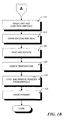
- FIGS. 1A-1B together form a flowchart depicting schematically the general steps involved in producing a phosphor according to the present invention.
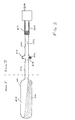
- FIG. 2 is a schematic diagram of components used during fabrication of a phosphor according to the present invention.
- the present invention is directed to an improved phosphor material similar to the prior art phosphor described above, and a method for producing this and other phosphor materials.
- the phosphor according to the present invention is a polycrystalline powder.
- this powder is zinc selenide (ZnSe) doped with at least one secondary material.
- the secondary material is a rare earth element that is activated by the addition of free oxygen.
- the material is a non-rare earth material, with no oxygen activation.
- the preferred method steps of the invention are depicted in a flow diagram in FIG. 1.
- the desired purity for the starting host material is at least 99.9999%. However, less pure materials may be used if purged of certain deleterious impurities.
- One material that is sufficiently pure in its starting state is CVD grade zinc selenide available from Phase 4 Infrared Corp., Lowell, MA. However, if it is necessary to remove deleterious impurities, such as sulfur, nickel, cobalt, carbon and iron, known purification techniques may be used. This is shown in FIG. 1 as step 102.
- the raw host material is milled and sieved to about one-micron average particle size using a ceramic surfaced mill (such as agate or zirconia) or a ceramic-surfaced vortex air mill (step 104).
- a ceramic surfaced mill such as agate or zirconia
- a ceramic-surfaced vortex air mill step 104
- the desired dopant is added along with the appropriate fluxing agent (step 106).
- the dopant is preferably added as an aqueous solution to a molar concentration of 0.0002 - 0.0010.
- the dopant includes a rare earth element such as europium (Eu), samarium (Sm), neodymium (Nd), gadolinium (Gd), holmium (Ho), erbium (Er) and ytterbium (Yb).
- a rare earth element such as europium (Eu), samarium (Sm), neodymium (Nd), gadolinium (Gd), holmium (Ho), erbium (Er) and ytterbium (Yb).
- Cerium-Terbium (Ce-Tb) and Cerium-Terbium-Erbium (Ce-Tb-Er) may also be used.
- the rare earth dopants provide high photoluminescence when activated by the addition of free oxygen.
- a source of oxygen is diffused into the host along with the dopant.
- the oxygen source is a chlorate or nitrate. Examples include potassium chlorate (KClO 3 ), silver chlorate (AgClO 4 ) or silver nitrate (AgNO 3 ).
- KCLO 3 potassium chlorate
- AgClO 4 silver chlorate
- AgNO 3 silver nitrate
- the use of gaseous oxygen as an activator is less desirable, as it is difficult to achieve uniform distribution of the oxygen throughout the doped material. While the use of most chlorates or nitrates results in an additional unnecessary material in the resulting phosphor, one may be used that is not particularly deleterious to the performance of the phosphor. Zinc chlorate would be a desirable material for this purpose, but tends to decompose at a temperature too low to withstand subsequent processing of the phosphor.
- the rare earth dopant is added as a material with the chemical structure XCl 3 , where X is the desired rare earth element or combination of elements.
- An appropriate flux such as zinc chloride (ZnCl 2 ) is also added to the material to promote diffusion of the dopant and the oxygen-contributing additive into the host material.
- ZnCl 2 fluxing agent is added in an amount of 0.1-5.0% by weight. The flux reduces the effective melting temperature of the host, allowing for purging at lower temperatures.
- the host powder is dried in a dessicator at approximately 70-100° C for about 2-3 hours (step 110).
- the powder is then annealed at a temperature of 1000-1200° C to diffuse the dopant and oxygen-contributor, to form complex crystal defects with the rare earth material and the oxygen-contributor and to remove any fracture defects caused by milling (step 114).
- the material is then washed with ultrapure water, dried and loaded into an ampoule (step 116).
- An appropriate quartz ampoule 202 is shown in FIG. 2 with the milled, doped ZnSe powder 206 residing in a powder-containing section 214 of the ampoule.
- the ampoule has different diameter regions of different lengths.
- the powder-containing section 214 is approximately 150 mm in length, with a diameter of 33-38 mm.
- Narrow ampoule sections 216, 220 are each approximately 150 mm in length with a diameter of 9-12 mm.
- the open end of ampoule section 220 is connected to vacuum hose 224 that leads to vacuum pump 208.
- the component trap 218 has a diameter larger than that of the narrow sections 216, 220, but smaller than powder section 214.
- the trap 218 is sized so that a portion of it will contain a chuck 222 of material used to generate a particular metal vapor environment during the purifying process.
- the trap 218 is an annular cavity that is axially symmetric about an axis passing through the length of the ampoule.
- the chuck is zinc, and is used to generate a zinc vapor atmosphere, as described below.
- the ampoule has a constriction 219 between section 216 and trap 218 that is narrower than the diameter of chuck 222 so that the chuck can be loaded into the ampoule after the powder, and will not enter the powder section 214 and contaminate the host.
- the description that follows makes reference to both the method steps of FIGS. 1A and 1B and the ampoule components shown in FIG. 2.
- the vacuum hose 224 is connected to the open end of ampoule section 220.
- the ampoule is pumped down to less than 10 -6 Torr and sealed using a gas torch or a vacuum valve (step 118).
- Broken lines 226 in FIG. 2 are used to indicate the location at which the ampoule is sealed in the preferred embodiment.
- the sealed ampoule is then placed in a two-zone furnace, the labels "Zone I" and "Zone II" being used in FIG. 2 to indicate which sections of the ampoule are located in which zone.
- the ampoule is then heated to further process the host powder. During the time that it is heated, it is maintained at a horizontal angle, and slowly rotated (at approximately 0.3-1.0 RPM) (step 120).
- Zone I is heated to a temperature of 900-1200° C, while Zone II is simultaneously heated to a temperature of 880-1180° C.
- the temperature in Zone I is high enough to drive high vapor pressure impurities out of the host powder.
- the temperature in Zone II is high enough to vaporize a portion of the chuck 222. This creates a metal vapor overpressure in the ampoule, providing an atmosphere for the powder during processing.
- the use of metal vapors, such as zinc, tellurium or cadmium, allows the creation of a solid solution with the host that can modify the electronic properties of the host crystal.
- the use of a zinc overpressure can decrease zinc vacancy defects in the host, while overpressures of tellurium and cadmium can modify the crystal bandgap to shift the wavelength of luminescence and decrease the concentration of shallow electron traps, thereby reducing afterglow.
- the temperatures of the ampoule are maintained for 1-3 hours, after which Zone I is cooled to about 470° C, and Zone II is cooled to about 300° C (step 122).
- the ampoule is maintained at these temperatures, while being rotated, for another 1-20 hours, depending on the quantity of phosphor being processed.
- materials with a high vapor pressure at the process temperature e.g., adsorbed gases, excess materials such as zinc or silicon, etc.
- the ampoule is removed from the furnace and allowed to cool to room temperature.
- the ampoule 202 may then be opened by first drilling a small hole ( ⁇ 0.1 mm diameter) in it with a diamond drill.
- the ampoule may be safely opened completely with a diamond saw, and the purified powder removed (step 124).
- the cooled phosphor is then sieved to allow the smaller, desired particles to be separated from the larger ones (step 126). If wet sieving or sedimentation is used, an ultrapure water solution should be used, and the phosphor should be subsequently annealed to remove any oxide layer that forms.
- the dopant does not include a rare earth material.
- the dopant has the chemical structure XCl 2 , where X is one of a number of different elements or a combination of a number of those elements.
- X may be copper (Cu), tellurium (Te), cadmium (Cd), silver (Ag), potassium (K), manganese (Mn), magnesium (Mg), calcium (Ca), strontium (Sr), and barium (Ba).
- These dopants are added to the host powder in the same way as described above for the rare earth dopants, except that no oxygen-contributing materials are necessary to activate the dopant. Thus, no chlorate or nitrate material would be added. However, the remainder of the method is the same, including the vacuum purification of the material.
- a phosphor has a host material that is doped with a dopant having the chemical structure XCl 3 , where X is a rare earth element or combination of elements.
- a free oxygen contributor is also added to provide the free oxygen necessary to activate the rare earth dopant.
- the processing of the phosphor includes the heating of the phosphor in an overpressure environment of zinc, cadmium or tellurium. The heating is done in a two-temperature zone enclosed environment, so that impurities in the phosphor powder are condensed out on the cooler surface.
- the dopant may be a material that is not a rare earth element, such as copper, tellurium, cadmium, silver, potassium, manganese, magnesium, calcium, strontium, and barium.
Landscapes
- Chemical & Material Sciences (AREA)
- Inorganic Chemistry (AREA)
- Engineering & Computer Science (AREA)
- Materials Engineering (AREA)
- Organic Chemistry (AREA)
- Luminescent Compositions (AREA)
Applications Claiming Priority (4)
| Application Number | Priority Date | Filing Date | Title |
|---|---|---|---|
| US9328098P | 1998-07-17 | 1998-07-17 | |
| US93280P | 1998-07-17 | ||
| US313565 | 1999-05-14 | ||
| US09/313,565 US6254806B1 (en) | 1998-07-17 | 1999-05-14 | High efficiency polycrystalline phosphors and method of making same |
Publications (3)
| Publication Number | Publication Date |
|---|---|
| EP0972816A2 true EP0972816A2 (fr) | 2000-01-19 |
| EP0972816A3 EP0972816A3 (fr) | 2000-07-12 |
| EP0972816B1 EP0972816B1 (fr) | 2004-04-14 |
Family
ID=26787350
Family Applications (1)
| Application Number | Title | Priority Date | Filing Date |
|---|---|---|---|
| EP99113410A Expired - Lifetime EP0972816B1 (fr) | 1998-07-17 | 1999-07-12 | Phosphores polycristallins à rendement élevé et méthode de fabrication |
Country Status (3)
| Country | Link |
|---|---|
| US (1) | US6254806B1 (fr) |
| EP (1) | EP0972816B1 (fr) |
| DE (1) | DE69916375T2 (fr) |
Cited By (1)
| Publication number | Priority date | Publication date | Assignee | Title |
|---|---|---|---|---|
| EP1199886A1 (fr) * | 2000-10-13 | 2002-04-24 | Applied Scintillation Technologies Ltd. | Caméra infra-rouge avec DTC revêtu de phosphore |
Families Citing this family (5)
| Publication number | Priority date | Publication date | Assignee | Title |
|---|---|---|---|---|
| CA2509417A1 (fr) * | 2002-12-20 | 2004-07-08 | Ifire Technology Corp. | Phosphores passives par le nitrure d'aluminium pour afficheurs electroluminescents |
| CN100446279C (zh) * | 2004-02-18 | 2008-12-24 | 财团法人工业技术研究院 | 发光二极管 |
| US20070242141A1 (en) * | 2006-04-14 | 2007-10-18 | Sony Corporation And Sony Electronics Inc. | Adjustable neutral density filter system for dynamic range compression from scene to imaging sensor |
| US7700920B2 (en) * | 2007-08-20 | 2010-04-20 | Radiation Monitoring Devices, Inc. | ZnSe scintillators |
| US20120018923A1 (en) * | 2010-07-20 | 2012-01-26 | Haochuan Jiang | System and method for forming a ceramic scintillator |
Family Cites Families (3)
| Publication number | Priority date | Publication date | Assignee | Title |
|---|---|---|---|---|
| JPH02306585A (ja) * | 1989-05-22 | 1990-12-19 | Hitachi Chem Co Ltd | 薄膜el素子の製造法 |
| JPH02306591A (ja) * | 1989-05-22 | 1990-12-19 | Hitachi Chem Co Ltd | 薄膜el素子の製造法 |
| JP3644131B2 (ja) * | 1995-08-25 | 2005-04-27 | 株式会社デンソー | El素子の製造方法 |
-
1999
- 1999-05-14 US US09/313,565 patent/US6254806B1/en not_active Expired - Lifetime
- 1999-07-12 DE DE69916375T patent/DE69916375T2/de not_active Expired - Lifetime
- 1999-07-12 EP EP99113410A patent/EP0972816B1/fr not_active Expired - Lifetime
Cited By (2)
| Publication number | Priority date | Publication date | Assignee | Title |
|---|---|---|---|---|
| EP1199886A1 (fr) * | 2000-10-13 | 2002-04-24 | Applied Scintillation Technologies Ltd. | Caméra infra-rouge avec DTC revêtu de phosphore |
| US7075576B2 (en) | 2000-10-13 | 2006-07-11 | Applied Scintillation Technologies, Ltd. | CCD camera having an anti-stokes phosphor bound thereto |
Also Published As
| Publication number | Publication date |
|---|---|
| DE69916375D1 (de) | 2004-05-19 |
| EP0972816B1 (fr) | 2004-04-14 |
| DE69916375T2 (de) | 2005-05-04 |
| US6254806B1 (en) | 2001-07-03 |
| EP0972816A3 (fr) | 2000-07-12 |
Similar Documents
| Publication | Publication Date | Title |
|---|---|---|
| Brebrick et al. | Composition stability limits of PbTe. II | |
| US4857228A (en) | Phosphors and methods of preparing the same | |
| US8012257B2 (en) | Methods for controllable doping of aluminum nitride bulk crystals | |
| US7763226B2 (en) | Method of manufacturing an aluminum nitride powder | |
| EP2497812B1 (fr) | Procédé de production d'une substance fluorescente à base de beta-sialon | |
| JPH11502610A (ja) | 活性化発光ナノクリスタリン粒子をドープしたガラスマトリックス | |
| EP0258908A2 (fr) | Matière fluorescente à grain ultrafin | |
| KR20150118198A (ko) | 나이트라이드계 레드 형광체들 | |
| EP2483205B1 (fr) | Matériau composite à base de skuttérudite garnie de gasb et son procédé de fabrication | |
| CN1089359C (zh) | 低余辉发光物质 | |
| Chong et al. | Photoluminescence of sol–gel-derived Y2O3: Eu3+ thin-film phosphors with Mg2+ and Al3+ co-doping | |
| EP0972816B1 (fr) | Phosphores polycristallins à rendement élevé et méthode de fabrication | |
| Taghavinia et al. | Nanocrystalline Zn2SiO4: Mn2+ grown in oxidized porous silicon | |
| KR20150067259A (ko) | 형광체의 제조방법 | |
| US7329370B2 (en) | Transparent polycrystalline ceramic scintillators and methods of preparing the same | |
| KR100384985B1 (ko) | 형광체,그제조방법및그것을사용한음극선관 | |
| JP4072620B2 (ja) | 酸化亜鉛超微粒子および酸化亜鉛超微粒子の製造方法 | |
| US20030094597A1 (en) | Isotopically enriched luminescent materials and methods of making same | |
| KR100733009B1 (ko) | 스트론튬-바륨 알루미네이트계 형광체 제조 | |
| JP3265356B2 (ja) | 発光材料及びその製造方法 | |
| US4427570A (en) | High-quantum efficiency, long-lived luminescing refractory oxides | |
| US20240417885A1 (en) | Methods of Growing Co-Doped Cerium Calcium Lutetium-Yttrium Oxyorthosilicate Scintillation Crystals and Related Crystals | |
| JPH0439385A (ja) | 赤外可視変換蛍光体 | |
| Fujihara et al. | Synthesis Process of BaMgAl10 O 17: Eu2+ from Sol-Gel-Derived Eu2+-Activated Fluoride Precursors without H 2 Annealing Treatments | |
| Fernández et al. | Localized luminescence in ZnO: Mn ceramics |
Legal Events
| Date | Code | Title | Description |
|---|---|---|---|
| PUAI | Public reference made under article 153(3) epc to a published international application that has entered the european phase |
Free format text: ORIGINAL CODE: 0009012 |
|
| AK | Designated contracting states |
Kind code of ref document: A2 Designated state(s): DE GB NL |
|
| AX | Request for extension of the european patent |
Free format text: AL;LT;LV;MK;RO;SI |
|
| PUAL | Search report despatched |
Free format text: ORIGINAL CODE: 0009013 |
|
| AK | Designated contracting states |
Kind code of ref document: A3 Designated state(s): AT BE CH CY DE DK ES FI FR GB GR IE IT LI LU MC NL PT SE |
|
| AX | Request for extension of the european patent |
Free format text: AL;LT;LV;MK;RO;SI |
|
| 17P | Request for examination filed |
Effective date: 20000623 |
|
| AKX | Designation fees paid |
Free format text: DE GB NL |
|
| 17Q | First examination report despatched |
Effective date: 20020816 |
|
| GRAP | Despatch of communication of intention to grant a patent |
Free format text: ORIGINAL CODE: EPIDOSNIGR1 |
|
| GRAS | Grant fee paid |
Free format text: ORIGINAL CODE: EPIDOSNIGR3 |
|
| GRAA | (expected) grant |
Free format text: ORIGINAL CODE: 0009210 |
|
| AK | Designated contracting states |
Kind code of ref document: B1 Designated state(s): DE GB NL |
|
| PG25 | Lapsed in a contracting state [announced via postgrant information from national office to epo] |
Ref country code: NL Free format text: LAPSE BECAUSE OF FAILURE TO SUBMIT A TRANSLATION OF THE DESCRIPTION OR TO PAY THE FEE WITHIN THE PRESCRIBED TIME-LIMIT Effective date: 20040414 |
|
| REG | Reference to a national code |
Ref country code: GB Ref legal event code: FG4D |
|
| REF | Corresponds to: |
Ref document number: 69916375 Country of ref document: DE Date of ref document: 20040519 Kind code of ref document: P |
|
| NLV1 | Nl: lapsed or annulled due to failure to fulfill the requirements of art. 29p and 29m of the patents act | ||
| PLBE | No opposition filed within time limit |
Free format text: ORIGINAL CODE: 0009261 |
|
| STAA | Information on the status of an ep patent application or granted ep patent |
Free format text: STATUS: NO OPPOSITION FILED WITHIN TIME LIMIT |
|
| 26N | No opposition filed |
Effective date: 20050117 |
|
| PGFP | Annual fee paid to national office [announced via postgrant information from national office to epo] |
Ref country code: DE Payment date: 20160728 Year of fee payment: 18 Ref country code: GB Payment date: 20160722 Year of fee payment: 18 |
|
| REG | Reference to a national code |
Ref country code: DE Ref legal event code: R119 Ref document number: 69916375 Country of ref document: DE |
|
| GBPC | Gb: european patent ceased through non-payment of renewal fee |
Effective date: 20170712 |
|
| PG25 | Lapsed in a contracting state [announced via postgrant information from national office to epo] |
Ref country code: GB Free format text: LAPSE BECAUSE OF NON-PAYMENT OF DUE FEES Effective date: 20170712 Ref country code: DE Free format text: LAPSE BECAUSE OF NON-PAYMENT OF DUE FEES Effective date: 20180201 |