EP0972908B1 - Procédé pour déterminer les caractéristiques d'un trépan du type racleur - Google Patents
Procédé pour déterminer les caractéristiques d'un trépan du type racleur Download PDFInfo
- Publication number
- EP0972908B1 EP0972908B1 EP99305258A EP99305258A EP0972908B1 EP 0972908 B1 EP0972908 B1 EP 0972908B1 EP 99305258 A EP99305258 A EP 99305258A EP 99305258 A EP99305258 A EP 99305258A EP 0972908 B1 EP0972908 B1 EP 0972908B1
- Authority
- EP
- European Patent Office
- Prior art keywords
- cutters
- bit
- cutter
- plane
- projection
- Prior art date
- Legal status (The legal status is an assumption and is not a legal conclusion. Google has not performed a legal analysis and makes no representation as to the accuracy of the status listed.)
- Expired - Lifetime
Links
- 238000000034 method Methods 0.000 title claims description 46
- 239000003550 marker Substances 0.000 claims description 10
- 238000005553 drilling Methods 0.000 claims description 7
- 230000000694 effects Effects 0.000 claims description 7
- 238000004458 analytical method Methods 0.000 description 13
- 238000004590 computer program Methods 0.000 description 5
- 229910003460 diamond Inorganic materials 0.000 description 4
- 239000010432 diamond Substances 0.000 description 4
- 238000012986 modification Methods 0.000 description 3
- 230000004048 modification Effects 0.000 description 3
- 239000000758 substrate Substances 0.000 description 3
- UONOETXJSWQNOL-UHFFFAOYSA-N tungsten carbide Chemical compound [W+]#[C-] UONOETXJSWQNOL-UHFFFAOYSA-N 0.000 description 3
- 229910000831 Steel Inorganic materials 0.000 description 2
- 239000012530 fluid Substances 0.000 description 2
- 239000000463 material Substances 0.000 description 2
- 239000010959 steel Substances 0.000 description 2
- 239000011230 binding agent Substances 0.000 description 1
- 230000015572 biosynthetic process Effects 0.000 description 1
- 238000004364 calculation method Methods 0.000 description 1
- 238000005352 clarification Methods 0.000 description 1
- 238000004140 cleaning Methods 0.000 description 1
- 238000007796 conventional method Methods 0.000 description 1
- 238000001816 cooling Methods 0.000 description 1
- 238000005755 formation reaction Methods 0.000 description 1
- 239000011159 matrix material Substances 0.000 description 1
- 229910052751 metal Inorganic materials 0.000 description 1
- 239000002184 metal Substances 0.000 description 1
- 229910001092 metal group alloy Inorganic materials 0.000 description 1
- 230000035515 penetration Effects 0.000 description 1
- 238000004663 powder metallurgy Methods 0.000 description 1
- 239000007787 solid Substances 0.000 description 1
- 238000004804 winding Methods 0.000 description 1
Images
Classifications
-
- E—FIXED CONSTRUCTIONS
- E21—EARTH OR ROCK DRILLING; MINING
- E21B—EARTH OR ROCK DRILLING; OBTAINING OIL, GAS, WATER, SOLUBLE OR MELTABLE MATERIALS OR A SLURRY OF MINERALS FROM WELLS
- E21B10/00—Drill bits
- E21B10/42—Rotary drag type drill bits with teeth, blades or like cutting elements, e.g. fork-type bits, fish tail bits
- E21B10/43—Rotary drag type drill bits with teeth, blades or like cutting elements, e.g. fork-type bits, fish tail bits characterised by the arrangement of teeth or other cutting elements
-
- Y—GENERAL TAGGING OF NEW TECHNOLOGICAL DEVELOPMENTS; GENERAL TAGGING OF CROSS-SECTIONAL TECHNOLOGIES SPANNING OVER SEVERAL SECTIONS OF THE IPC; TECHNICAL SUBJECTS COVERED BY FORMER USPC CROSS-REFERENCE ART COLLECTIONS [XRACs] AND DIGESTS
- Y10—TECHNICAL SUBJECTS COVERED BY FORMER USPC
- Y10S—TECHNICAL SUBJECTS COVERED BY FORMER USPC CROSS-REFERENCE ART COLLECTIONS [XRACs] AND DIGESTS
- Y10S706/00—Data processing: artificial intelligence
- Y10S706/902—Application using ai with detail of the ai system
- Y10S706/928—Earth science
- Y10S706/929—Geological, e.g. seismology
Definitions
- the invention relates to rotary drag-type drill bits for use in drilling holes in subsurface formations and of the kind where a plurality of cutters are mounted on a bit body having an axis of rotation.
- One common form of bit has a shank for connection to a drill string, a plurality of circumferentially spaced blades on the bit body extending outwardly away from the central axis of rotation of the bit, and a plurality of cutting elements mounted along each blade.
- a passage in the bit body supplies drilling fluid to nozzles in the surface of the bit for cleaning and cooling the cutters.
- the invention is particularly, but not exclusively, applicable to drill bits in which some or all of the cutters are preform cutters formed, at least in part, from polycrystalline diamond or other superhard material.
- One common form of cutter comprises a tablet, usually circular or part-circular, made up of a superhard table of polycrystalline diamond, providing the front cutting face of the cutter, bonded to a substrate which is usually of cemented tungsten carbide.
- the bit body may be machined from solid metal, usually steel, or may be moulded using a powder metallurgy process in which tungsten carbide power is infiltrated with a metal alloy binder in a furnace so as to form a hard matrix.
- the cutters on the drill bit have cutting edges which, together, define an overall cutting profile which defines the surface shape of the bottom of the borehole which the bit drills.
- the cutting profile is substantially continuous over the leading face of the bit so as to form a comparatively smooth bottom hole profile.
- each cutter may be affected by the action of a number of other cutters which are at adjacent relative radial and axial positions. It will be appreciated that such cutters will not necessarily be directly adjacent one another on the actual bit body but may well be angularly displaced circumferentially from one another by a considerable distance.
- EP 384734, US 4475606 and GB 2241266 all describe arrangements in which the locations of cutters, as the bit is rotated, are projected onto a plane thereby producing an illustration of the cutting profile of the bit.
- the present invention sets out to provide a novel and improved method of determining characteristics of a drill bit design, and particularly for estimating the effect of cutter placement on the forces acting on the bit in use.
- a method of determining characteristics of a rotary drag-type drill bit of the kind comprising a plurality of cutters mounted on a bit body having an axis of rotation, the method comprising the steps of:
- Said plane intersects the selected cutter and may pass through the axis of rotation of the bit.
- the projection of the shape of the selected cutter, and the projections of the shapes of the other cutters will usually be normal to said plane.
- the direction of projection is not normal to the plane, as will be described.
- the two-dimensional cells may be of any shape but are preferably rectangular.
- the cells may be square.
- said second marker may be assigned to cells of the array which do not overlie the projection of the selected cutter.
- the cutters are moved axially while being rotated about the bit axis so as to simulate the axial movement of the bit during drilling.
- the cutters are rotated about the bit axis in a direction which corresponds to reverse rotation of the bit, and are moved axially in a direction which corresponds to withdrawal of the bit from a borehole being drilled.
- the steps of the method are carried out for all of the cutters, each being the selected cutter in turn.
- the parameters which are determined of the region of the array which remains defined by cells having only said first marker may be selected from the cut area, shear length, moments of area, and second moments of area defined by said cells. The calculation of such parameters will be described in further detail below.
- the method includes the further step of combining the forces acting at the respective cutters to estimate force parameters for the drill bit as a whole.
- said force parameters may be selected from weight-on-bit, torque, out of balance force and out of balance angle.
- bits are sometimes subject to "bit whirl" where the rotating bit precesses around the walls of the borehole, as the bit rotates, with the result that the central axis of the bit itself rotates about the axis of the borehole.
- bit whirl the rotating bit precesses around the walls of the borehole, as the bit rotates, with the result that the central axis of the bit itself rotates about the axis of the borehole.
- the method according to the invention may be modified so that the projection of the shape of each cutter, relative to said plane, is in a direction corresponding to the direction of motion of that cutter through said plane, as modified by a prescribed motion of the bit axis.
- the method according to the invention may be used in conjunction with conventional dynamic analysis techniques in order to carry out dynamic analysis of a bit design, as will be described.
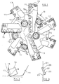
- FIG. 1 and 2 there is shown an end view of one kind of full bore drill bit of the type to which the method of the present invention may be applied.
- the bit body 10 is typically machined from steel and has a threaded shank (not shown) at one end for connection to the drill string.
- the operative end face of the bit body is formed with a number of blades 11 radiating outwardly from the central area of the bit, the blades carrying cutters 12 spaced apart along the length thereof.
- the bit gauge section includes kickers 13 which contact the walls of the borehole in use, to stabilise the bit in the borehole.
- a central passage (not shown) in the bit body and shank delivers drilling fluid through nozzles 14 mounted in the bit body, in known manner, to clean and cool the cutters.
- Each cutter 12 comprises a preform cutting element 15 mounted on a carrier 16 in the form of a stud which is secured in a socket in the blade 11.
- Each cutting element 15 comprises a circular tablet having a front facing table 17 of polycrystalline diamond, providing the front cutting face of the element, bonded to a substrate 18 of cemented tungsten carbide, the substrate being in turn bonded to the carrier 16.
- the object of the method according to the invention is to enable a steady state analysis of a particular design of drill bit to be carried out so as to determine the contribution made by the cutters to the forces acting on the bit in use. This is achieved by first determining the shape of the portion of each cutter which contributes to the cutting action; determining certain parameters of that portion of the cutter; using those parameters in suitable cutter force algorithms in order to estimate the forces acting at each cutter; and then combining the forces acting at each of the cutters on the drill bit to determine the total effect of the cutters on the forces acting on the bit.
- a computerised representation of the shapes of the cutters of a proposed or existing design of drill bit is created, including the locations of the cutters and their orientations with respect to the bit axis. It is common practice to create computerised representations of drill bit designs for various purposes and there are programs available for creating such representations.
- a plane 21 is created which passes through the bit centre axis and the centre 22 of the polycrystalline diamond layer of the cutter.
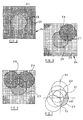
- the shape ofthe cutter 20 is projected normally on to the plane 21, as indicated at 23 in Figures 3 and 4.
- the cutter will normally exhibit negative back rake, that is to say it will be inclined forwardly in the direction of rotation ofthe drill bit as shown in Figures 2 and 3, and the cutter may also exhibit side rake, that is to say it may be inclined to face inwardly or outwardly with respect to the axis of rotation of the drill bit. Accordingly, the projection 23 of the cutter on to the plane 21 will normally be an ellipse if the cutter is circular. However, for simplicity, the projections of the cutters will be shown as circular in the accompanying drawings.
- the projection 23 ofthe selected cutter is overlaid with a two-dimensional array 24 comprising a large number of square cells 25 which are considerably smaller in area than the projection 23 of the selected cutter.
- each cell may have a side length which is about one hundredth of the diameter of the cutter.
- the cells 25 are shown larger than they would normally be in practice.
- a value of 1 is assigned to all those cells 25 which lie at least partly within the projected cutter shape 23 and a value of 0 is assigned to all those cells 25 lying outside the projected cutter shape.
- the bit is rotated in reverse relative to the plane 21 so that each cutter on the bit passes in succession through the plane 21.
- the reverse rotation of the bit is accompanied by axial movement of the bit in a direction corresponding to withdrawal from the borehole so as to simulate the reverse of the penetration which occurs during drilling. Consequently, each cutter moves upwards in the axial direction as it moves rearwardly through the plane 21.
- FIG. 5 shows a case where the projection 26 of the other cutter partly overlies the projection 23 of the selected cutter 20.
- values of 0 are assigned to all the cells 25 which overlie both the projection 23 of the selected cutter and the projection 26 of the other cutter.
- Figure 6 shows the projection 28 of another cutter which projection at least partly overlies the projection 23 of the selected cutter.
- the reverse rotation and axial withdrawal of the bit relative to the plane 21 is continued until the projections of no more cutters interfere with the projection of the selected cutter being examined.
- the cells 25 remaining with a value of 1 define the effective cutting area of the projection 23 of the selected cutter 20.
- the cut area, shear length, moments of area and second moments of area for the cells having a value of 1 are calculated for the selected cutter. These are the parameters which affect the force acting at the cutter.
- the cut area is the total area of the cells with a value of 1;
- the shear length is the length of the exposed curved cutting edge 29 of the projection ofthe cutter, the ends of the cutting edge being indicated at 30 and 31.
- the moments of area of the cells are the products of the areas of the cells and their distances from the vertical and horizontal axes 32, 33 of the projection 23.
- the second moments of area are the areas of the cells multiplied by the squares of the distances from these axes.
- Steps 1 to 10 are repeated for each cutter on the bit, each being the selected cutter in turn.
- the cut area properties of the cutters are input into suitable cutter force algorithms to estimate the force acting at each cutter. Those skilled in the art will be aware of the appropriate algorithms for this purpose.
- the cutter forces of all the cutters are then combined, using conventional techniques, to determine the weight-on-bit, torque, out of balance force and out of balance angle for the bit, attributable to the cutters.
- the above steps will normally be carried out by an appropriate computer program and the program will be arranged to provide an output of the required information in any suitable form.
- the program may also be arranged to provide a pictorial representation of the cut shapes provided by the cutters and the cutting profile of the drill bit.
- the method when incorporated in a computer program, may allow rapid analysis of modifications to a bit design and it may be seen readily how modifications in cutter location and orientation will affect the forces acting on the bit. It thus provides a tool whereby, for example, out of balance forces and an out of balance angle can be predetermined for a particular design of drill bit, this information being used to control bit whirl.
- the method may be modified by simulating rotational precessing of the bit axis as the steps of the method proceed. This may be achieved by altering the direction of the projection of each cutter on to the array 25 so that the projection is not normal to the array but is in the actual direction of the motion of each cutter, as a result of rotation of the bit axis, as it passes through the plane of the array.
Landscapes
- Engineering & Computer Science (AREA)
- Life Sciences & Earth Sciences (AREA)
- Geology (AREA)
- Mining & Mineral Resources (AREA)
- Mechanical Engineering (AREA)
- Physics & Mathematics (AREA)
- Environmental & Geological Engineering (AREA)
- Fluid Mechanics (AREA)
- General Life Sciences & Earth Sciences (AREA)
- Geochemistry & Mineralogy (AREA)
- Earth Drilling (AREA)
- Numerical Control (AREA)
Claims (15)
- Procédé de détermination des caractéristiques d'un trépan de forage rotatif du type à lames, comprenant plusieurs éléments de coupe (12) montés sur un corps de trépan (10) comportant un axe de rotation, le procédé comprenant les étapes ci-dessous:(a) établissement d'une représentation des formes desdits éléments de coupe (12) ainsi que de leurs emplacements et de leurs orientations par rapport à l'axe du trépan;(b) établissement d'un plan (21) fixe par rapport à un élément de coupe sélectionné parmi lesdits éléments de coupe (20);(c) projection sur le plan fixe (21) de la forme dudit élément de coupe sélectionné parmi les éléments de coupe; et caractérisé par les étapes ci-dessous:(d) superposition de la projection (23) de lélément de coupe sélectionné (20) d'un réseau bidimensionnel (24) de cellules bidimensionnelles ayant une surface plus petite que la projection (23);(e) attribution d'un premier marqueur aux cellules du réseau (24) qui sont superposées à la projection (23) de l'élément de coupe sélectionné (20);(f) rotation des éléments de coupe (12) autour de l'axe du trépan jusqu'à ce que tous les autres éléments de coupe (12) ont traversé au moins une fois ledit plan (21);(g) déplacement des éléments de coupe (12) dans une direction axiale lors de la rotation autour de l'axe du trépan de sorte à représenter le déplacement axial du trépan au cours du forage;(h) projection des formes desdits autres éléments de coupe (12) sur ledit plan (21) lors de leur passage à travers le plan (21);(i) attribution d'un deuxième marqueur aux cellules du réseau (24) qui sont superposées à la projection (23) de l'élément de coupe sélectionné (20) et aux projections de quelconques autres éléments de coupe (12);(j) détermination d'un ou de plusieurs paramètres de la région du réseau (24) restant définie par les cellules comportant uniquement ledit premier marqueur;(k) estimation sur la base dudit paramètre ou desdits paramètres d'une ou de plusieurs forces agissant au niveau de l'emplacement dudit élément de coupe sélectionné (20) dans un trépan de forage effectif;(l) répétition des étapes (a) à (k) pour chaque élément de coupe (12) du trépan de forage; et(m) combinaison des forces estimées pour déterminer l'effet total exercé par les éléments de coupe sur les forces agissant sur le trépan de forage.
- Procédé selon la revendication 1, dans lequel ledit plan (21) traverse l'axe de rotation du trépan.
- Procédé selon les revendications 1 ou 2, dans lequel ledit plan (21) coupe l'élément de coupe sélectionné (20).
- Procédé selon la revendication 3, dans lequel le centre de l'élément de coupe sélectionné (20) se situe sur ledit plan (21).
- Procédé selon l'une quelconque des revendications précédentes, dans lequel les projections des formes des éléments de coupe (12) sont perpendiculaires audit plan (21).
- Procédé selon l'une quelconque des revendications précédentes, dans lequel les cellules bidimensionnelles du réseau (24) sont rectangulaires.
- Procédé selon l'une quelconque des revendications précédentes, dans lequel, au cours de l'étape (e) du procédé, ledit deuxième marqueur est attribué aux cellules du réseau (24) non superposées à la projection (23) de l'élément de coupe sélectionné (20).
- Procédé selon l'une quelconque des revendications précédentes, dans lequel les éléments de coupe (12) sont déplacés axialement dans une direction correspondant au retrait du trépan d'un trou de forage en cours de forage.
- Procédé selon l'une quelconque des revendications précédentes, dans lequel les éléments de coupe (12) sont tournés autour de l'axe du trépan dans une direction correspondant à la rotation inverse du trépan.
- Procédé selon l'une quelconque des revendications précédentes, dans lequel la rotation des éléments de coupe (12) est poursuivie jusqu'à ce qu'aucune projection des autres éléments de coupe (12) n'est superposée à la projection (23) de l'élément de coupe sélectionné (20) lors du passage des autres éléments de coupe (12) à travers le plan (21).
- Procédé selon l'une quelconque des revendications précédentes, dans lequel les étapes du procédé sont exécutées pour tous les éléments de coupe (12), chacun constituant successivement l'élément de coupe sélectionné.
- Procédé selon l'une quelconque des revendications précédentes, dans lequel les paramètres déterminés de la région du réseau (24) restant définie par les cellules comportant uniquement ledit premier marqueur sont choisis parmi la surface de coupe, la longueur de cisaillement, des moments de l'aire et des deuxièmes moments de l'aire définis par lesdites cellules.
- Procédé selon l'une quelconque des revendications précédentes, englobant l'étape additionnelle de combinaison des forces agissant sur les éléments de coupe respectifs pour estimer les paramètres de force du trépan de forage en tant qu'ensemble.
- Procédé selon la revendication 13, dans lequel lesdits paramètres de force sont choisis parmi le poids appliqué au trépan, le couple, la force de déséquilibre et l'angle de déséquilibre.
- Procédé selon l'une quelconque des revendications précédentes, dans lequel la projection de la forme de chaque élément de coupe (12) par rapport audit plan s'étend dans une direction correspondant à la direction de déplacement de cet élément de coupe (12) à travers ledit plan, modifiée par un déplacement prescrit de l'axe du trépan.
Applications Claiming Priority (3)
| Application Number | Priority Date | Filing Date | Title |
|---|---|---|---|
| GB9815125 | 1998-07-14 | ||
| GB9815125A GB2339810B (en) | 1998-07-14 | 1998-07-14 | A method of determining characteristics of a rotary drag-type drill bit |
| US09/160,282 US6246974B1 (en) | 1998-07-14 | 1998-09-24 | Method of determining characteristics of a rotary drag-type drill bit |
Publications (3)
| Publication Number | Publication Date |
|---|---|
| EP0972908A2 EP0972908A2 (fr) | 2000-01-19 |
| EP0972908A3 EP0972908A3 (fr) | 2000-12-13 |
| EP0972908B1 true EP0972908B1 (fr) | 2005-01-12 |
Family
ID=26314020
Family Applications (1)
| Application Number | Title | Priority Date | Filing Date |
|---|---|---|---|
| EP99305258A Expired - Lifetime EP0972908B1 (fr) | 1998-07-14 | 1999-07-02 | Procédé pour déterminer les caractéristiques d'un trépan du type racleur |
Country Status (3)
| Country | Link |
|---|---|
| US (1) | US6246974B1 (fr) |
| EP (1) | EP0972908B1 (fr) |
| GB (1) | GB2339810B (fr) |
Cited By (1)
| Publication number | Priority date | Publication date | Assignee | Title |
|---|---|---|---|---|
| CN102943626A (zh) * | 2012-12-06 | 2013-02-27 | 邵金安 | 冲击旋切钻头及使用该钻头的入岩钻机 |
Families Citing this family (34)
| Publication number | Priority date | Publication date | Assignee | Title |
|---|---|---|---|---|
| GB2346628B (en) * | 1999-01-29 | 2002-09-18 | Camco Internat | A method of predicting characteristics of a rotary drag-type drill bit design |
| US6460631B2 (en) * | 1999-08-26 | 2002-10-08 | Baker Hughes Incorporated | Drill bits with reduced exposure of cutters |
| US6394200B1 (en) | 1999-10-28 | 2002-05-28 | Camco International (U.K.) Limited | Drillout bi-center bit |
| US7693695B2 (en) | 2000-03-13 | 2010-04-06 | Smith International, Inc. | Methods for modeling, displaying, designing, and optimizing fixed cutter bits |
| US7020597B2 (en) | 2000-10-11 | 2006-03-28 | Smith International, Inc. | Methods for evaluating and improving drilling operations |
| US9482055B2 (en) | 2000-10-11 | 2016-11-01 | Smith International, Inc. | Methods for modeling, designing, and optimizing the performance of drilling tool assemblies |
| US6785641B1 (en) | 2000-10-11 | 2004-08-31 | Smith International, Inc. | Simulating the dynamic response of a drilling tool assembly and its application to drilling tool assembly design optimization and drilling performance optimization |
| US8589124B2 (en) | 2000-08-09 | 2013-11-19 | Smith International, Inc. | Methods for modeling wear of fixed cutter bits and for designing and optimizing fixed cutter bits |
| US6695073B2 (en) * | 2001-03-26 | 2004-02-24 | Halliburton Energy Services, Inc. | Rock drill bits, methods, and systems with transition-optimized torque distribution |
| US7451836B2 (en) | 2001-08-08 | 2008-11-18 | Smith International, Inc. | Advanced expandable reaming tool |
| CA2531397C (fr) | 2003-07-09 | 2010-04-13 | Smith International, Inc. | Procedes de modelisation de trepans a couteaux a usure ou fixes et de conception et d'optimisation de trepans a couteaux fixes |
| CA2523325A1 (fr) * | 2004-10-12 | 2006-04-12 | Dwayne P. Terracina | Allocation de l'ecoulement pour trepans |
| US7831419B2 (en) | 2005-01-24 | 2010-11-09 | Smith International, Inc. | PDC drill bit with cutter design optimized with dynamic centerline analysis having an angular separation in imbalance forces of 180 degrees for maximum time |
| US7441612B2 (en) | 2005-01-24 | 2008-10-28 | Smith International, Inc. | PDC drill bit using optimized side rake angle |
| GB0521693D0 (en) * | 2005-10-25 | 2005-11-30 | Reedhycalog Uk Ltd | Representation of whirl in fixed cutter drill bits |
| WO2007056554A1 (fr) * | 2005-11-08 | 2007-05-18 | Baker Hughes Incorporated | Procedes servant a optimiser l'efficacite et la duree de vie de trepans rotatifs et trepans rotatifs conçus pour une efficacite et une duree de vie optimisees |
| US8141665B2 (en) * | 2005-12-14 | 2012-03-27 | Baker Hughes Incorporated | Drill bits with bearing elements for reducing exposure of cutters |
| US7814997B2 (en) | 2007-06-14 | 2010-10-19 | Baker Hughes Incorporated | Interchangeable bearing blocks for drill bits, and drill bits including same |
| CA2748660A1 (fr) * | 2009-01-14 | 2010-07-22 | Halliburton Energy Services, Inc. | Trepans rotatifs ayant des caracteristiques optimisees d'ecoulement de fluide |
| CA2773331C (fr) * | 2009-02-27 | 2018-05-01 | Newtech Drilling Products, Llc | Trepan pour forage du sol |
| WO2010115146A2 (fr) * | 2009-04-02 | 2010-10-07 | Jones Mark L | Foret pour foreuse |
| EP2425089A4 (fr) * | 2009-04-30 | 2014-06-04 | Baker Hughes Inc | Blocs de support pour trépans, ensembles de trépans comprenant des blocs de support et procédés associés |
| WO2011044147A2 (fr) | 2009-10-05 | 2011-04-14 | Baker Hughes Incorporated | Trépans et outils de forage souterrain et leurs procédés de fabrication, et procédés de forage directionnel et excentré |
| US8839886B2 (en) * | 2009-11-09 | 2014-09-23 | Atlas Copco Secoroc Llc | Drill bit with recessed center |
| US8505634B2 (en) | 2009-12-28 | 2013-08-13 | Baker Hughes Incorporated | Earth-boring tools having differing cutting elements on a blade and related methods |
| EP2531690B1 (fr) | 2010-02-05 | 2019-04-03 | Baker Hughes, a GE company, LLC | Éléments de coupe profilés sur des trépans et autres outils de forage, et procédés de formation de tels éléments |
| US8851207B2 (en) | 2011-05-05 | 2014-10-07 | Baker Hughes Incorporated | Earth-boring tools and methods of forming such earth-boring tools |
| SA111320671B1 (ar) | 2010-08-06 | 2015-01-22 | بيكر هوغيس انكور | عوامل القطع المشكلة لادوات ثقب الارض و ادوات ثقب الارض شاملة عوامل القطع هذه و الطرق المختصة بها |
| WO2012148965A2 (fr) | 2011-04-25 | 2012-11-01 | Newtech Drilling Products, Llc | Trépan permettant de forer au travers de la terre et autres matériaux durs |
| US9316058B2 (en) | 2012-02-08 | 2016-04-19 | Baker Hughes Incorporated | Drill bits and earth-boring tools including shaped cutting elements |
| GB2543674B (en) * | 2014-08-26 | 2020-09-16 | Halliburton Energy Services Inc | Shape-based modeling of interactions between downhole drilling tools and rock formation |
| WO2016183172A1 (fr) | 2015-05-11 | 2016-11-17 | Smith International, Inc. | Procédé de conception et d'optimisation de trépans à lames fixes au moyen d'une vitesse, d'un déplacement, de forces et d'un travail de lame dynamiques |
| US10526850B2 (en) | 2015-06-18 | 2020-01-07 | Halliburton Energy Services, Inc. | Drill bit cutter having shaped cutting element |
| US12031383B2 (en) * | 2019-03-07 | 2024-07-09 | Halliburton Energy Services, Inc. | Shaped cutter arrangements |
Family Cites Families (13)
| Publication number | Priority date | Publication date | Assignee | Title |
|---|---|---|---|---|
| US4475606A (en) | 1982-08-09 | 1984-10-09 | Dresser Industries, Inc. | Drag bit |
| US5042596A (en) | 1989-02-21 | 1991-08-27 | Amoco Corporation | Imbalance compensated drill bit |
| CA1333282C (fr) | 1989-02-21 | 1994-11-29 | J. Ford Brett | Outil de forage a auto-equilibrage |
| US5010789A (en) | 1989-02-21 | 1991-04-30 | Amoco Corporation | Method of making imbalanced compensated drill bit |
| GB2241266A (en) | 1990-02-27 | 1991-08-28 | Dresser Ind | Intersection solution method for drill bit design |
| US5099929A (en) | 1990-05-04 | 1992-03-31 | Dresser Industries, Inc. | Unbalanced PDC drill bit with right hand walk tendencies, and method of drilling right hand bore holes |
| US5238075A (en) * | 1992-06-19 | 1993-08-24 | Dresser Industries, Inc. | Drill bit with improved cutter sizing pattern |
| US5605198A (en) * | 1993-12-09 | 1997-02-25 | Baker Hughes Incorporated | Stress related placement of engineered superabrasive cutting elements on rotary drag bits |
| US5592996A (en) * | 1994-10-03 | 1997-01-14 | Smith International, Inc. | Drill bit having improved cutting structure with varying diamond density |
| US5613093A (en) * | 1994-10-12 | 1997-03-18 | Kolb; George P. | Apparatus and method for drill design |
| US5607024A (en) * | 1995-03-07 | 1997-03-04 | Smith International, Inc. | Stability enhanced drill bit and cutting structure having zones of varying wear resistance |
| US5937958A (en) * | 1997-02-19 | 1999-08-17 | Smith International, Inc. | Drill bits with predictable walk tendencies |
| US6095262A (en) * | 1998-08-31 | 2000-08-01 | Halliburton Energy Services, Inc. | Roller-cone bits, systems, drilling methods, and design methods with optimization of tooth orientation |
-
1998
- 1998-07-14 GB GB9815125A patent/GB2339810B/en not_active Expired - Lifetime
- 1998-09-24 US US09/160,282 patent/US6246974B1/en not_active Expired - Lifetime
-
1999
- 1999-07-02 EP EP99305258A patent/EP0972908B1/fr not_active Expired - Lifetime
Cited By (1)
| Publication number | Priority date | Publication date | Assignee | Title |
|---|---|---|---|---|
| CN102943626A (zh) * | 2012-12-06 | 2013-02-27 | 邵金安 | 冲击旋切钻头及使用该钻头的入岩钻机 |
Also Published As
| Publication number | Publication date |
|---|---|
| GB2339810A (en) | 2000-02-09 |
| GB9815125D0 (en) | 1998-09-09 |
| US6246974B1 (en) | 2001-06-12 |
| EP0972908A3 (fr) | 2000-12-13 |
| GB2339810B (en) | 2002-05-22 |
| EP0972908A2 (fr) | 2000-01-19 |
Similar Documents
| Publication | Publication Date | Title |
|---|---|---|
| EP0972908B1 (fr) | Procédé pour déterminer les caractéristiques d'un trépan du type racleur | |
| US5042596A (en) | Imbalance compensated drill bit | |
| US5010789A (en) | Method of making imbalanced compensated drill bit | |
| CA1333282C (fr) | Outil de forage a auto-equilibrage | |
| US7426459B2 (en) | Methods for designing single cone bits and bits made using the methods | |
| CA2605196C (fr) | Trepan a lames a chute libre et methodes de fabrication connexes | |
| EP0554568B1 (fr) | Taillant mosaique du trépan "drag-bit" avec un profil d'usure inégal | |
| US8631883B2 (en) | Sectorial force balancing of drill bits | |
| US8082134B2 (en) | Techniques for modeling/simulating, designing optimizing, and displaying hybrid drill bits | |
| US6644422B1 (en) | Pantograph underreamer | |
| EP0467580B1 (fr) | Trépan de forage souterrain et procédés associés | |
| WO1994015058A1 (fr) | Trepan comportant un broyeur de fragments a couche compacte diamantee polycristalline et un insert metallique dur au niveau d'une surface etalon | |
| EP1146200A1 (fr) | Conception d'un trépan de forage à l'aide de réseaux neuronaux | |
| CA2776578A1 (fr) | Optimisation de la structure de coupe d'une meche | |
| US20180023372A1 (en) | Methods of designing and forming earth-boring tools using a plurality of depth of cut values | |
| GB2346628A (en) | Method of predicting forces on drill bits | |
| US6151960A (en) | Method of determining characteristics of a rotary drag-type drill bit | |
| US20010020551A1 (en) | Rotary drag-type drill bits and methods of designing such bits | |
| US10428588B2 (en) | Methods and drill bit designs for preventing the substrate of a cutting element from contacting a formation | |
| US20030136588A1 (en) | Roller cone drill bit having designed walk characteristics | |
| US10954721B2 (en) | Earth-boring tools and related methods | |
| US8818775B2 (en) | Methods of designing earth-boring tools using a plurality of wear state values and related methods of forming earth-boring tools | |
| EP0350045B1 (fr) | Trépan avec éléments de coupe composites | |
| EP1008718B1 (fr) | Trépans racleurs rotatifs et méthodes pour leur conception | |
| GB2434391A (en) | Drill bit with secondary cutters for hard formations |
Legal Events
| Date | Code | Title | Description |
|---|---|---|---|
| PUAI | Public reference made under article 153(3) epc to a published international application that has entered the european phase |
Free format text: ORIGINAL CODE: 0009012 |
|
| AK | Designated contracting states |
Kind code of ref document: A2 Designated state(s): BE DE |
|
| AX | Request for extension of the european patent |
Free format text: AL;LT;LV;MK;RO;SI |
|
| PUAL | Search report despatched |
Free format text: ORIGINAL CODE: 0009013 |
|
| AK | Designated contracting states |
Kind code of ref document: A3 Designated state(s): AT BE CH CY DE DK ES FI FR GB GR IE IT LI LU MC NL PT SE |
|
| AX | Request for extension of the european patent |
Free format text: AL;LT;LV;MK;RO;SI |
|
| RIC1 | Information provided on ipc code assigned before grant |
Free format text: 7E 21B 10/46 A, 7E 21B 10/42 B |
|
| 17P | Request for examination filed |
Effective date: 20010201 |
|
| AKX | Designation fees paid |
Free format text: BE DE |
|
| 17Q | First examination report despatched |
Effective date: 20040422 |
|
| GRAP | Despatch of communication of intention to grant a patent |
Free format text: ORIGINAL CODE: EPIDOSNIGR1 |
|
| GRAS | Grant fee paid |
Free format text: ORIGINAL CODE: EPIDOSNIGR3 |
|
| RBV | Designated contracting states (corrected) |
Designated state(s): BE DE FR IE |
|
| GRAA | (expected) grant |
Free format text: ORIGINAL CODE: 0009210 |
|
| AK | Designated contracting states |
Kind code of ref document: B1 Designated state(s): BE DE FR IE |
|
| REF | Corresponds to: |
Ref document number: 69923116 Country of ref document: DE Date of ref document: 20050217 Kind code of ref document: P |
|
| REG | Reference to a national code |
Ref country code: IE Ref legal event code: FG4D |
|
| PLBE | No opposition filed within time limit |
Free format text: ORIGINAL CODE: 0009261 |
|
| STAA | Information on the status of an ep patent application or granted ep patent |
Free format text: STATUS: NO OPPOSITION FILED WITHIN TIME LIMIT |
|
| ET | Fr: translation filed | ||
| 26N | No opposition filed |
Effective date: 20051013 |
|
| PGFP | Annual fee paid to national office [announced via postgrant information from national office to epo] |
Ref country code: DE Payment date: 20060629 Year of fee payment: 8 |
|
| PGFP | Annual fee paid to national office [announced via postgrant information from national office to epo] |
Ref country code: IE Payment date: 20060712 Year of fee payment: 8 |
|
| PGFP | Annual fee paid to national office [announced via postgrant information from national office to epo] |
Ref country code: FR Payment date: 20060719 Year of fee payment: 8 |
|
| PGFP | Annual fee paid to national office [announced via postgrant information from national office to epo] |
Ref country code: BE Payment date: 20060912 Year of fee payment: 8 |
|
| BERE | Be: lapsed |
Owner name: *CAMCO INTERNATIONAL (UK) LTD Effective date: 20070731 |
|
| PG25 | Lapsed in a contracting state [announced via postgrant information from national office to epo] |
Ref country code: DE Free format text: LAPSE BECAUSE OF NON-PAYMENT OF DUE FEES Effective date: 20080201 |
|
| REG | Reference to a national code |
Ref country code: IE Ref legal event code: MM4A |
|
| REG | Reference to a national code |
Ref country code: FR Ref legal event code: ST Effective date: 20080331 |
|
| PG25 | Lapsed in a contracting state [announced via postgrant information from national office to epo] |
Ref country code: BE Free format text: LAPSE BECAUSE OF NON-PAYMENT OF DUE FEES Effective date: 20070731 |
|
| PG25 | Lapsed in a contracting state [announced via postgrant information from national office to epo] |
Ref country code: FR Free format text: LAPSE BECAUSE OF NON-PAYMENT OF DUE FEES Effective date: 20070731 |
|
| PG25 | Lapsed in a contracting state [announced via postgrant information from national office to epo] |
Ref country code: IE Free format text: LAPSE BECAUSE OF NON-PAYMENT OF DUE FEES Effective date: 20070702 |