EP1008718B1 - Trépans racleurs rotatifs et méthodes pour leur conception - Google Patents
Trépans racleurs rotatifs et méthodes pour leur conception Download PDFInfo
- Publication number
- EP1008718B1 EP1008718B1 EP19990309759 EP99309759A EP1008718B1 EP 1008718 B1 EP1008718 B1 EP 1008718B1 EP 19990309759 EP19990309759 EP 19990309759 EP 99309759 A EP99309759 A EP 99309759A EP 1008718 B1 EP1008718 B1 EP 1008718B1
- Authority
- EP
- European Patent Office
- Prior art keywords
- bit
- rotary
- speed
- combination according
- drill bit
- Prior art date
- Legal status (The legal status is an assumption and is not a legal conclusion. Google has not performed a legal analysis and makes no representation as to the accuracy of the status listed.)
- Expired - Lifetime
Links
Images



Classifications
-
- E—FIXED CONSTRUCTIONS
- E21—EARTH OR ROCK DRILLING; MINING
- E21B—EARTH OR ROCK DRILLING; OBTAINING OIL, GAS, WATER, SOLUBLE OR MELTABLE MATERIALS OR A SLURRY OF MINERALS FROM WELLS
- E21B10/00—Drill bits
- E21B10/62—Drill bits characterised by parts, e.g. cutting elements, which are detachable or adjustable
-
- E—FIXED CONSTRUCTIONS
- E21—EARTH OR ROCK DRILLING; MINING
- E21B—EARTH OR ROCK DRILLING; OBTAINING OIL, GAS, WATER, SOLUBLE OR MELTABLE MATERIALS OR A SLURRY OF MINERALS FROM WELLS
- E21B10/00—Drill bits
- E21B10/42—Rotary drag type drill bits with teeth, blades or like cutting elements, e.g. fork-type bits, fish tail bits
Definitions
- the invention relates to the design of rotary drag-type drill bits for use in drilling holes in subsurface formations.
- drag-type drill bits comprise a bit body having a shank for connection to a drill string and a plurality of fixed cutters mounted on the bit body.
- a passage in the bit body supplies drilling fluid to nozzles in the surface of the bit for cleaning and cooling the cutters.
- the leading face of the bit comprises a number of circumferentially spaced blades extending outwardly away from the central axis of rotation of the bit, cutters being mounted along each blade.
- PDC polycrystalline diamond compact
- One common form of cutter comprises a tablet, usually circular or part-circular, made up of a superhard table of polycrystalline diamond, providing the front cutting face of the cutter, bonded to a substrate which is usually of cemented tungsten carbide.
- the bit body may be machined from solid metal, usually steel, or may be moulded using a powder metallurgy process in which tungsten carbide powder is infiltrated with a metal alloy binder in a furnace so as to form a hard matrix.
- a powder metallurgy process in which tungsten carbide powder is infiltrated with a metal alloy binder in a furnace so as to form a hard matrix.
- Torsional vibration is undesirable since it can lead to rapid wear of PDC bits, particularly in harder formations, due to damage to the cutters as a result of impact loads caused by the torsional vibration.
- Torsional vibration can have the effect that cutters on the drill bit may momentarily stop or be rotating backwards, i.e. in the reverse rotational direction to the normal forward direction of rotation of the drill bit during drilling.
- the effect of such reverse rotation on a PDC cutter may be to impose unusual loads on the cutter which tend to cause spalling or delamination, i.e. separation of part or all of the polycrystalline diamond facing from the tungsten carbide substrate. It would therefore be desirable to be able to design rotary drag-type drill bits which will not be susceptible to stick-slip, or to be able to select from existing or proposed bit designs those which will be less susceptible to this phenomenon.
- the present invention is based on the surprising discovery that bits exhibiting lateral vibration which increases with rotary bit speed may be less susceptible to stick-slip than bits which do not exhibit this characteristic. It has been found that increase in lateral vibration with increasing rotary bit speed is correlated with increase in bit torque. When a bit having this characteristic is subject to the rapid increases in rotary speed which occur during stick-slip, the increase in torque which results from the increase in speed serves to provide positive damping of the torsional vibrations, with the result that the bit drills more efficiently and is less susceptible to damage. The reduction of torsional vibrations may also reduce the risk of fatigue in the drill string.
- EP 0467580 describes a drill bit having its cutters arranged so as to cause a radial force imbalance.
- the present invention makes use of this discovery in the design of drill bits, either by allowing to be selected for development and manufacture those proposed bit designs which are found to have the above characteristic, or by specifically designing drill bits, or associated downhole components, in a manner to ensure that the bit or component will exhibit such characteristic.
- a combination with a rotary drag-type drill bit of a device characterised in that the device is responsive to rotary bit speed and adapted to increase the bit torque with increase in bit speed, the rotary bit speed responsive device being provided either on the drill bit itself, or on an additional downhole component which, in use, rotates with the drill bit.
- the rotary bit speed responsive device may include brake means adapted, in use, to bear on the formation being drilled with a force which increases with increase in rotary bit speed.
- the brake means may include elements which are displaced outwardly, with respect to the axis of rotation, to bear on the surrounding wall of the borehole in the formation being drilled.
- the brake means may comprise a number of formation-engaging elements which are displaceable outwardly under the action of power means selected from: hydraulic pressure of drilling fluid supplied to the drill bit during drilling; a source of electrical power; axial motion of the drill bit under weight-on-bit.
- the rotary bit speed responsive device may comprise means to modify the orientation of a number of cutters mounted on the drill bit.
- the device may be adapted to reduce the back-rake of cutters mounted on the drill bit with increasing rotary bit speed, since such reduction in back-rake will increase the bit torque.
- the device may be adapted to increase the depth of cut of cutters mounted on the drill bit with increasing rotary bit speed.
- the rotary bit speed responsive device may comprise means to increase the effective cutting diameter of the drill bit with increasing rotary bit speed. Such increase in effective cutting diameter will also increase the bit torque.
- the nominal diameter of the drill bit is preferably the maximum effective cutting diameter permitted by the rotary bit speed responsive device.
- the drill bit will drill a full diameter hole when rotating at maximum speed, and will drill a slightly undersize hole when the bit speed drops below the maximum. Since the variation in effective cutting diameter will mean that some parts of the borehole will be undersize, it may be necessary subsequently to ream out these portions of the borehole to the full diameter.
- the drill bit may include a number of cutters or abrasion elements mounted on the bit body for movement inwardly and outwardly relative to the axis of rotation of the bit, the cutters or abrasion elements being moved outwardly in response to increasing rotary bit speed.
- the device responsive to rotary bit speed in order to increase the bit torque with increase in bit speed may comprise a mass rotatable with the bit and located outwardly of the axis of rotation of the bit.
- a mass may be mounted in the bit body itself or in a further downhole component which is rotatable with the bit.
- Figure 1 shows the lateral vibration of a particular drag-type rotary drill bit (Bit A) plotted against rpm, the vibration being plotted as lateral acceleration in metres/s/s, and the data being acquired in laboratory drilling tests.
- Bit A is not stable, experiencing lateral vibration that rises quickly with rotary speed to 60m/s/s.
- Bit A is found to exhibit a very low incidence of stick-slip while drilling.
- Figures 2-5 show the patterns of lateral vibration in an 81 ⁇ 2 inch unbalanced drill bit (Bit B) with increase of rotary bit speed from 210 rpm to 300 rpm.
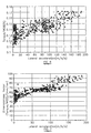
- Figures 6 and 7 show the correlation between lateral vibration and torque in Bit B.
- torque/weight-on-bit in feet, is plotted against lateral acceleration, in m/s/s, and it will be seen that increasing torque is accompanied by increasing lateral vibration in Bit B over three different tests, whereas in a test of a similar fourth balanced bit (Bit C), circled in Figures 6 and 7, the correlation does not occur and there is no significant increase in lateral vibration with increase in torque.
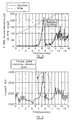
- Figures 8 and 9 further show the correlation between torque and lateral vibration in a further drill bit (Bit D).
- Bit D a further drill bit
- both rpm and lateral acceleration of the drill bit are plotted against time. Comparing Figure 8 with Figure 9, where torque is plotted against time, it will be seen that the pattern of variation in torque corresponds generally to the pattern of variation in lateral vibration, this being seen particularly in the correlation between the torque spike in Figure 9 which matches the vibration spike in Figure 8 in the 7-9 second time span.
- Figures 10 and 11 show graphs of torque plotted against rpm for Bit A, which exhibited low tendency to stick-slip, and it will be seen that in each case there is an increase in torque with increasing rpm. This is shown particularly clearly in Figure 10 which shows data acquired from laboratory test drilling. The characteristic is still present, though less strongly marked, in Figure 11 where the data was acquired from field drilling.
- Bit A and other bits having the characteristics described, exhibit a low tendency to stick-slip because of a coupling of lateral vibration and torque which produces a positive damping characteristic which may be referred to as "Dynamic Damping" because dynamic effects are providing positive damping to prevent stick-slip.
- the simplest application of the concept in bit design is to ascertain the appropriate relationships for proposed or existing bit designs to select those designs which exhibit the rising torque/rotary bit speed characteristic, or correlated lateral vibration or depth of cut characteristics, which have been shown to indicate low susceptibility to stick-slip.
- the effect of modifications to a basic bit design on stick-slip susceptibility can be determined by ascertaining these relationships for the modifications and selecting that modification where the relationships indicate that the actual drill bit will exhibit low susceptibility to stick-slip.
- the primary advantage of the invention is that it will allow proposed bit designs to be selected for lack of susceptibility to stick-slip before the bits are actually developed and manufactured.
- the characteristics of a proposed design may be determined by the use of analytical software by which a computer model of a proposed design of drill bit may be created, as previously mentioned.
- analytical software for the purposes of the present invention a particularly suitable form of analytical software is that of the kind which uses the methods described in U.S. Patent Application No. 09/160,282.
- This software takes account of the movement of a PDC bit (such as rpm and rate of penetration) and then calculates the total forces acting on the bit by summing all of the forces generated by cutters and other bit features.
- the software may therefore readily be used to produce torque/rpm data, or lateral vibrations/rpm or depth of cut/rpm data, in respect of any proposed design of drill bit.
- a further application of the present invention is to the active design of drill bits, or associated downhole components, to produce the rising torque/rpm characteristic which is now indicated as being desirable to avoid stick-slip.
- One simple method of providing for bit torque to increase with rotary bit speed is to provide the drill bit or an associated downhole component with a simple centrifugal governor. For example, a 100 kg mass rotating at 400 rpm at 83 ⁇ 4 inch radius would provide a torque of 1415 lb ft, and such an arrangement may provide sufficient positive damping to reduce the susceptibility to stick-slip to a useful extent.
- power sources may include drilling fluid pressure, stored energy (e.g. electrical energy stored during smooth drilling), or axial motion of the drill string under weight-on-bit.
- the braking device may interact with the cylindrical borehole wall or with the cutting face of the borehole.
- the braking device may take the form of brake elements spaced apart around the periphery of the drill bit or associated downhole component and arrange to be displaced outwardly into engagement with the borehole wall with increasing rotary bit speed.
- FIGS 12-14 show diagrammatically typical forms which such brake elements might take.
- the device is in the form of a curved pad 10 pivotally mounted at 11 adjacent the periphery 12 of the drill bit, the arrangement being such that the pad 10 trails the pivot 11 with respect to the direction of rotation indicated by the arrow 13.
- Figure 14 shows an arrangement in which a roller 16 is so mounted that it may be forced outwardly by a piston 17 to jam against the borehole wall.
- FIG. 15 shows diagrammatically one type of arrangement which makes use of the hydraulic pressure of the drilling fluid which is normally supplied under pressure to the drill bit during drilling.
- drilling fluid in conventional manner drilling fluid is pumped under pressure down the drill string 18 and is delivered to nozzles 19 in the leading face of the drill bit which cause the drilling fluid to flow outwardly across the leading face of the bit to cool and clean the cutters and to carry the cuttings upwardly past the gauge section of the bit to the surface through the annulus between the drill string and the wall of the borehole, such annulus being indicated diagrammatically at 20 in Figure 15.
- a passage 21 for drilling fluid leads to a control valve 22 which may selectively deliver drilling fluid through a passage 23 to the nozzles 19 or through a passage 24 to an hydraulic actuator 25, such as a piston and cylinder arrangement, for energising the brake pads 10, 14, 16 of Figures 12-14.
- the control valve 22 is arranged to divert a proportion of the drilling fluid from the nozzles 19 to the actuators 25 upon increase in the rotary speed of the drill bit or other component of the bottom assembly on which the brake devices may be mounted.
- the power for such a control valve could be generated from the flow of drilling fluid, using technologies well established, for example in mud pulse telemetry.
- the control unit for the valve 22 is preferably "strapped down" (i.e. attached to the drill string) and is activated by rate of change of rotary speed.
- Slip-stick typically operates over a period of around 10-20 seconds, so a rate of change corresponding to doubling rpm in 2.5-5 seconds would indicate the occurrence of stick-slip.
- Bit torque may also be varied by modifying the bits' "aggressivity", defined as its torque/WOB. Torque can be increased by, for example, reducing the back rake of PDC cutters mounted on the drill bit and reduced by, for example, engaging a depth of cut limiter. Conversely, therefore, torque may be increased by allowing the depth of cut to be increased.
- the power to operate such mechanisms is again preferably hydraulic.
- Another approach is to vary the bit torque by varying the effective cutting diameter of the drill bit. This may achieved by using an expanding bit which is enlarged above nominal size.
- Devices similar to the brake shoes described above could carry PDC or other cutters on an outwardly movable arm.
- cutters could be mounted on an hydraulically actuated piston member, such as indicated at 26 in Figure 16 and 27 in Figure 17, which slides along an inclined ramp into engagement with the surrounding wall of the borehole.
- a similar arrangement might also be used for outward movement of brake shoes for the arrangement previously described.
- the piston members 26 and 27 may be hydraulically actuated, for example by using a drilling fluid system of the kind shown in Figure 15.
- the maximum effective cutting diameter of the drill bit would be equivalent to the nominal diameter of the bit so that the moving pads would withdraw as the rotary speed drops, to reduce the borehole size, and expand to the nominal bit size as the rotary speed increases during slip. In this case a short undergauge portion of borehole would result. It is anticipated that a reaming device higher in the borehole (not necessarily integral with the drill bit) would correct this.
Landscapes
- Engineering & Computer Science (AREA)
- Life Sciences & Earth Sciences (AREA)
- Geology (AREA)
- Mining & Mineral Resources (AREA)
- Mechanical Engineering (AREA)
- Physics & Mathematics (AREA)
- Environmental & Geological Engineering (AREA)
- Fluid Mechanics (AREA)
- General Life Sciences & Earth Sciences (AREA)
- Geochemistry & Mineralogy (AREA)
- Earth Drilling (AREA)
Claims (12)
- Combinaison d'un trépan de forage rotatif du type à lames et d'un dispositif, caractérisée en ce que le dispositif (10) réagit à la vitesse de rotation du trépan et est destiné à accroítre le couple appliqué au trépan en fonction d'un accroissement de la vitesse du trépan, le dispositif réagissant à la vitesse de rotation du trépan (10) étant agencé sur le trépan de forage même ou sur un composant de fond additionnel, tournant en service avec le trépan de forage.
- Combinaison selon la revendication 1, dans laquelle le dispositif réagissant à la vitesse de rotation du trépan de forage (10) englobe des moyens de frein (10), destinés à peser en service sur la formation en cours de forage avec une force accrue en fonction d'un accroissement de la vitesse de rotation du trépan.
- Combinaison selon la revendication 2, dans laquelle les moyens de frein (10) englobent des éléments déplacés vers l'extérieur, par rapport à l'axe de rotation, pour peser sur la paroi environnante du trou de forage dans la formation en cours de forage.
- Combinaison selon la revendication 3, dans laquelle les moyens de frein (10) comprennent plusieurs éléments s'engageant dans la formation (10), pouvant être déplacés vers l'extérieur sous l'action d'un moyen d'alimentation d'énergie, sélectionné dans le groupe constitué de: la pression hydraulique du fluide de forage amené vers le trépan de forage au cours du forage; une source d'énergie électrique; le déplacement axial du trépan de forage en présence d'un couple appliqué au trépan.
- Combinaison selon la revendication 1, dans laquelle le dispositif réagissant à la vitesse de rotation du trépan comprend un moyen destiné à modifier l'orientation de plusieurs éléments de coupe montés sur le trépan de forage.
- Combinaison selon la revendication 5, dans laquelle le dispositif réagissant à la vitesse de rotation est destiné à réduire l'inclinaison arrière des éléments de coupe montés sur le trépan de forage en fonction d'un accroissement de la vitesse de rotation du trépan.
- Combinaison selon la revendication 5, dans laquelle le dispositif réagissant à la vitesse de rotation est destiné à accroítre la profondeur de coupe des éléments de coupe montés sur le trépan de forage en fonction d'un accroissement de la vitesse de rotation du trépan.
- Combinaison selon la revendication 1, dans laquelle le dispositif réagissant à la vitesse de rotation du trépan comprend un moyen (26, 27) destiné à accroítre le diamètre de coupe effectif du trépan de forage en fonction d'un accroissement de la vitesse de rotation du trépan.
- Combinaison selon la revendication 8, dans laquelle le diamètre nominal du trépan de forage correspond au diamètre de coupe effectif maximal permis par le dispositif réagissant à la vitesse de rotation du trépan.
- Combinaison selon les revendication 8 ou 9, dans laquelle le trépan de forage englobe plusieurs éléments de coupe ou éléments d'abrasion montés sur le corps du trépan en vue d'un déplacement vers l'intérieur et vers l'extérieur par rapport à l'axe de rotation du trépan, les éléments de coupe ou d'abrasion étant déplacés vers l'extérieur en réponse à un accroissement de la vitesse de rotation.
- Combinaison selon la revendication 1, dans laquelle le dispositif réagissant à la vitesse de rotation du trépan pour accroítre le couple appliqué au trépan en réponse à un accroissement de la vitesse du trépan comprend une masse additionnelle pouvant tourner avec le trépan et agencée vers l'extérieur de l'axe de rotation du trépan.
- Combinaison selon la revendication 11, dans laquelle la masse additionnelle est montée dans le corps du trépan même ou dans un composant de fond additionnel pouvant tourner avec le trépan.
Applications Claiming Priority (2)
| Application Number | Priority Date | Filing Date | Title |
|---|---|---|---|
| US210518 | 1994-03-17 | ||
| US21051898A | 1998-12-11 | 1998-12-11 |
Publications (3)
| Publication Number | Publication Date |
|---|---|
| EP1008718A2 EP1008718A2 (fr) | 2000-06-14 |
| EP1008718A3 EP1008718A3 (fr) | 2001-04-11 |
| EP1008718B1 true EP1008718B1 (fr) | 2004-09-15 |
Family
ID=22783223
Family Applications (1)
| Application Number | Title | Priority Date | Filing Date |
|---|---|---|---|
| EP19990309759 Expired - Lifetime EP1008718B1 (fr) | 1998-12-11 | 1999-12-03 | Trépans racleurs rotatifs et méthodes pour leur conception |
Country Status (2)
| Country | Link |
|---|---|
| EP (1) | EP1008718B1 (fr) |
| DE (1) | DE69920145T2 (fr) |
Families Citing this family (2)
| Publication number | Priority date | Publication date | Assignee | Title |
|---|---|---|---|---|
| GB0009266D0 (en) * | 2000-04-15 | 2000-05-31 | Camco Int Uk Ltd | Method and apparatus for predicting an operating characteristic of a rotary earth boring bit |
| CN109322653B (zh) * | 2017-07-28 | 2022-03-01 | 中国石油天然气股份有限公司 | 井下钻柱粘滑特征的地面快速评价方法和装置 |
Family Cites Families (4)
| Publication number | Priority date | Publication date | Assignee | Title |
|---|---|---|---|---|
| US4941951A (en) * | 1989-02-27 | 1990-07-17 | Anadrill, Inc. | Method for improving a drilling process by characterizing the hydraulics of the drilling system |
| CA2045094C (fr) * | 1990-07-10 | 1997-09-23 | J. Ford Brett | Meche de forage a faible friction et methodes connexes |
| US5864058A (en) * | 1994-09-23 | 1999-01-26 | Baroid Technology, Inc. | Detecting and reducing bit whirl |
| US5842149A (en) * | 1996-10-22 | 1998-11-24 | Baker Hughes Incorporated | Closed loop drilling system |
-
1999
- 1999-12-03 DE DE69920145T patent/DE69920145T2/de not_active Expired - Lifetime
- 1999-12-03 EP EP19990309759 patent/EP1008718B1/fr not_active Expired - Lifetime
Also Published As
| Publication number | Publication date |
|---|---|
| DE69920145T2 (de) | 2005-09-22 |
| DE69920145D1 (de) | 2004-10-21 |
| EP1008718A2 (fr) | 2000-06-14 |
| EP1008718A3 (fr) | 2001-04-11 |
Similar Documents
| Publication | Publication Date | Title |
|---|---|---|
| EP0430590B1 (fr) | Perfectionnements aux trépans de forage rotatifs | |
| US5186268A (en) | Rotary drill bits | |
| US4938291A (en) | Cutting tool for cutting well casing | |
| EP0266864B1 (fr) | Outil de fraisage pour couper un tubage de puits | |
| US8196679B2 (en) | Expandable reamers for subterranean drilling and related methods | |
| US5099934A (en) | Rotary drill bits | |
| CA2605196C (fr) | Trepan a lames a chute libre et methodes de fabrication connexes | |
| CA2590439C (fr) | Trepan avec configuration asymetrique des patins de taille | |
| US7000715B2 (en) | Rotary drill bits exhibiting cutting element placement for optimizing bit torque and cutter life | |
| EP0972908B1 (fr) | Procédé pour déterminer les caractéristiques d'un trépan du type racleur | |
| US7461706B2 (en) | Drilling apparatus with percussive action cutter | |
| US8631883B2 (en) | Sectorial force balancing of drill bits | |
| CA2831324C (fr) | Systemes de forage et outils a lames fixes a profondeur de coupe reglable afin de commander le couple sur outil | |
| EP0522553A1 (fr) | Pointe de perçage à stabilité accrue | |
| US20010020551A1 (en) | Rotary drag-type drill bits and methods of designing such bits | |
| US6575256B1 (en) | Drill bit with lateral movement mitigation and method of subterranean drilling | |
| NO327181B1 (no) | System og fremgangsmate for boring ved bruk av roterende styrbar boresammenstilling | |
| US20120031671A1 (en) | Drill Bits With Rolling Cone Reamer Sections | |
| GB2346628A (en) | Method of predicting forces on drill bits | |
| EP1008718B1 (fr) | Trépans racleurs rotatifs et méthodes pour leur conception | |
| US20060102388A1 (en) | Drilling tool | |
| WO2019190456A1 (fr) | Outil de forage de fond de trou avec ensembles de contrôleurs de profondeur de coupe comprenant des contrôleurs activables de profondeur de coupe | |
| Taylor et al. | Unique PDC bit technologies combine to consistently reduce drilling time in interbedded formations | |
| Taylor et al. | Unique PDC bit technologies combine to reduce drilling time in interbedded formations |
Legal Events
| Date | Code | Title | Description |
|---|---|---|---|
| PUAI | Public reference made under article 153(3) epc to a published international application that has entered the european phase |
Free format text: ORIGINAL CODE: 0009012 |
|
| AK | Designated contracting states |
Kind code of ref document: A2 Designated state(s): BE DE FR GB IE IT |
|
| AX | Request for extension of the european patent |
Free format text: AL;LT;LV;MK;RO;SI |
|
| PUAL | Search report despatched |
Free format text: ORIGINAL CODE: 0009013 |
|
| AK | Designated contracting states |
Kind code of ref document: A3 Designated state(s): AT BE CH CY DE DK ES FI FR GB GR IE IT LI LU MC NL PT SE |
|
| AX | Request for extension of the european patent |
Free format text: AL;LT;LV;MK;RO;SI |
|
| 17P | Request for examination filed |
Effective date: 20010521 |
|
| AKX | Designation fees paid |
Free format text: BE DE FR GB IE IT |
|
| 17Q | First examination report despatched |
Effective date: 20030905 |
|
| GRAP | Despatch of communication of intention to grant a patent |
Free format text: ORIGINAL CODE: EPIDOSNIGR1 |
|
| GRAS | Grant fee paid |
Free format text: ORIGINAL CODE: EPIDOSNIGR3 |
|
| GRAA | (expected) grant |
Free format text: ORIGINAL CODE: 0009210 |
|
| AK | Designated contracting states |
Kind code of ref document: B1 Designated state(s): BE DE FR GB IE IT |
|
| REG | Reference to a national code |
Ref country code: GB Ref legal event code: FG4D |
|
| REG | Reference to a national code |
Ref country code: IE Ref legal event code: FG4D |
|
| REF | Corresponds to: |
Ref document number: 69920145 Country of ref document: DE Date of ref document: 20041021 Kind code of ref document: P |
|
| PLBE | No opposition filed within time limit |
Free format text: ORIGINAL CODE: 0009261 |
|
| STAA | Information on the status of an ep patent application or granted ep patent |
Free format text: STATUS: NO OPPOSITION FILED WITHIN TIME LIMIT |
|
| ET | Fr: translation filed | ||
| 26N | No opposition filed |
Effective date: 20050616 |
|
| REG | Reference to a national code |
Ref country code: FR Ref legal event code: PLFP Year of fee payment: 17 |
|
| REG | Reference to a national code |
Ref country code: FR Ref legal event code: PLFP Year of fee payment: 18 |
|
| REG | Reference to a national code |
Ref country code: FR Ref legal event code: PLFP Year of fee payment: 19 |
|
| REG | Reference to a national code |
Ref country code: FR Ref legal event code: PLFP Year of fee payment: 20 |
|
| PGFP | Annual fee paid to national office [announced via postgrant information from national office to epo] |
Ref country code: DE Payment date: 20181120 Year of fee payment: 20 Ref country code: IE Payment date: 20181210 Year of fee payment: 20 |
|
| PGFP | Annual fee paid to national office [announced via postgrant information from national office to epo] |
Ref country code: GB Payment date: 20181128 Year of fee payment: 20 Ref country code: FR Payment date: 20181011 Year of fee payment: 20 Ref country code: BE Payment date: 20181015 Year of fee payment: 20 |
|
| PGFP | Annual fee paid to national office [announced via postgrant information from national office to epo] |
Ref country code: IT Payment date: 20181220 Year of fee payment: 20 |
|
| REG | Reference to a national code |
Ref country code: DE Ref legal event code: R071 Ref document number: 69920145 Country of ref document: DE |
|
| REG | Reference to a national code |
Ref country code: BE Ref legal event code: MK Effective date: 20191203 |
|
| REG | Reference to a national code |
Ref country code: GB Ref legal event code: PE20 Expiry date: 20191202 |
|
| PG25 | Lapsed in a contracting state [announced via postgrant information from national office to epo] |
Ref country code: GB Free format text: LAPSE BECAUSE OF EXPIRATION OF PROTECTION Effective date: 20191202 |
|
| REG | Reference to a national code |
Ref country code: IE Ref legal event code: MK9A |
|
| PG25 | Lapsed in a contracting state [announced via postgrant information from national office to epo] |
Ref country code: IE Free format text: LAPSE BECAUSE OF EXPIRATION OF PROTECTION Effective date: 20191203 |