EP0972920A2 - Spannrollenanordnung für einen Endlostrieb an einer Brennkraftmaschine - Google Patents
Spannrollenanordnung für einen Endlostrieb an einer Brennkraftmaschine Download PDFInfo
- Publication number
- EP0972920A2 EP0972920A2 EP99107237A EP99107237A EP0972920A2 EP 0972920 A2 EP0972920 A2 EP 0972920A2 EP 99107237 A EP99107237 A EP 99107237A EP 99107237 A EP99107237 A EP 99107237A EP 0972920 A2 EP0972920 A2 EP 0972920A2
- Authority
- EP
- European Patent Office
- Prior art keywords
- internal combustion
- combustion engine
- bearing
- endless drive
- flange
- Prior art date
- Legal status (The legal status is an assumption and is not a legal conclusion. Google has not performed a legal analysis and makes no representation as to the accuracy of the status listed.)
- Withdrawn
Links
Images




Classifications
-
- F—MECHANICAL ENGINEERING; LIGHTING; HEATING; WEAPONS; BLASTING
- F16—ENGINEERING ELEMENTS AND UNITS; GENERAL MEASURES FOR PRODUCING AND MAINTAINING EFFECTIVE FUNCTIONING OF MACHINES OR INSTALLATIONS; THERMAL INSULATION IN GENERAL
- F16H—GEARING
- F16H7/00—Gearings for conveying rotary motion by endless flexible members
- F16H7/08—Means for varying tension of belts, ropes or chains
- F16H7/10—Means for varying tension of belts, ropes or chains by adjusting the axis of a pulley
- F16H7/12—Means for varying tension of belts, ropes or chains by adjusting the axis of a pulley of an idle pulley
- F16H7/1254—Means for varying tension of belts, ropes or chains by adjusting the axis of a pulley of an idle pulley without vibration damping means
- F16H7/1281—Means for varying tension of belts, ropes or chains by adjusting the axis of a pulley of an idle pulley without vibration damping means where the axis of the pulley moves along a substantially circular path
-
- F—MECHANICAL ENGINEERING; LIGHTING; HEATING; WEAPONS; BLASTING
- F02—COMBUSTION ENGINES; HOT-GAS OR COMBUSTION-PRODUCT ENGINE PLANTS
- F02B—INTERNAL-COMBUSTION PISTON ENGINES; COMBUSTION ENGINES IN GENERAL
- F02B67/00—Engines characterised by the arrangement of auxiliary apparatus not being otherwise provided for, e.g. the apparatus having different functions; Driving auxiliary apparatus from engines, not otherwise provided for
- F02B67/04—Engines characterised by the arrangement of auxiliary apparatus not being otherwise provided for, e.g. the apparatus having different functions; Driving auxiliary apparatus from engines, not otherwise provided for of mechanically-driven auxiliary apparatus
- F02B67/06—Engines characterised by the arrangement of auxiliary apparatus not being otherwise provided for, e.g. the apparatus having different functions; Driving auxiliary apparatus from engines, not otherwise provided for of mechanically-driven auxiliary apparatus driven by means of chains, belts, or like endless members
-
- F—MECHANICAL ENGINEERING; LIGHTING; HEATING; WEAPONS; BLASTING
- F16—ENGINEERING ELEMENTS AND UNITS; GENERAL MEASURES FOR PRODUCING AND MAINTAINING EFFECTIVE FUNCTIONING OF MACHINES OR INSTALLATIONS; THERMAL INSULATION IN GENERAL
- F16H—GEARING
- F16H7/00—Gearings for conveying rotary motion by endless flexible members
- F16H7/08—Means for varying tension of belts, ropes or chains
- F16H2007/0802—Actuators for final output members
- F16H2007/0806—Compression coil springs
-
- F—MECHANICAL ENGINEERING; LIGHTING; HEATING; WEAPONS; BLASTING
- F16—ENGINEERING ELEMENTS AND UNITS; GENERAL MEASURES FOR PRODUCING AND MAINTAINING EFFECTIVE FUNCTIONING OF MACHINES OR INSTALLATIONS; THERMAL INSULATION IN GENERAL
- F16H—GEARING
- F16H7/00—Gearings for conveying rotary motion by endless flexible members
- F16H7/08—Means for varying tension of belts, ropes or chains
- F16H2007/0802—Actuators for final output members
- F16H2007/0812—Fluid pressure
Definitions
- the invention relates to a tensioner roller arrangement for an endless drive on an internal combustion engine according to the preamble of claim 1.
- the invention has for its object a generic tensioner assembly to improve in such a way that a smaller overall space is required.
- the housing supporting the angle lever as a motor support is designed for the internal combustion engine, this housing being one of the Internal combustion engine associated bearing flange and a support flange, which is assigned to a bearing designed separately from the internal combustion engine.
- This housing being one of the Internal combustion engine associated bearing flange and a support flange, which is assigned to a bearing designed separately from the internal combustion engine.
- engine supports which are independent, mostly massive and rigid component between a bearing attached to the vehicle body and the internal combustion engine is arranged. It is advantageous for the motor support takes up space here by integrating the tension pulley.
- the tensioning pulley according to the invention can be prepared together with the motor support as a pre-assembly unit be put.
- the one that carries the angle lever of the tensioning roller Housing further flange surfaces for the storage of other components, such as an oil cooler and / or an oil filter.
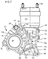
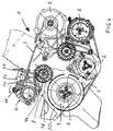
- An endless drive designated overall with 1 for the drive of not shown Auxiliary units 2 of an internal combustion engine schematically indicated in Figure 7 has a multi-groove V-ribbed belt 3. This runs from a pulley 4 on a crankshaft stump 6 of the internal combustion engine via a deflection roller 8 of a tensioning roller arrangement to a tensioning roller 10 and from this to the other, not shown auxiliary units 2 and these in turn on the pulley 4th
- the tensioning roller arrangement comprises a motor support 12 designed for the internal combustion engine Housing 14.
- An angle lever 18 is on a flange 16 of this housing 14 rotatably supported about a pivot point 20, at one of the ends 22, 24 of this angle lever 18 the tension roller 10 is rotatably mounted.
- a first leg extends between this pivot point 20 and the tensioning roller 10 28 of the angle lever 18 extends almost at right angles to the other End 24 towards a second leg 30.
- an elastic grip At this other end 24 an elastic grips Prestressed clamping element 32 in the form of a hydraulic tensioner 34 on this Angle lever.
- this tensioner 34 At the opposite end 36 of this tensioner 34, this is on a mounting eye 38 of the housing 14 pivotally supported.
- the motor support 12 has an integrally formed bearing flange 40 with a total of three Attachment points 42, 44, 46 through which a fixed connection by means of screws between this engine support 12 and an end face 48 of the crankcase 50 the internal combustion engine is provided.
- the motor support 12 carries a support flange almost perpendicular to this bearing flange 40 52, to which a bearing 54 formed separately from the internal combustion engine can be fastened is.
- This bearing 54 in turn has fastening means 56 for the body side Striking on.
- a carrying eye 60 is arranged for the transport of the internal combustion engine together with the tensioning roller arrangement.
- this carrying eye 60 can be a further, integral component of the motor support 12.
- the motor support 12 is designed as an aluminum die-cast part and has on it the Side facing the internal combustion engine has a wall 64 provided with ribs 62, 63 on.
- the leg 30 is with an integrally formed force application surface 66 equipped for fitting a form-fitting tool.
- this target 66 is a key-like tool in the assembly of the endless drive 1 Arranged arrow direction according to Figure 7 acting counterclockwise, so that the Tensioning roller 10 pivoting about the pivot point 20 of the angle lever 18 in FIG is pivoted to the right. As a result, the winding of the endless drive 1 is made considerably easier.
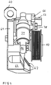
- the tension roller 10 is with a double-row ball bearing 70 on one by means of a Screw 72 supported on the angle lever 18 fixed inner pot 74.
- the Pivot point 20 of the angle lever 18 is guided by a inside a clamping sleeve 76 Screw 78 passes through, one according to Figure 6 on the left and right Washer 80 is arranged.
- Tensioner 34 is interposed with an elastic decoupling 82 and hinged on the angle lever 18 by means of a sleeve 84. In corresponding The other eye 86 of the tensioner 34 is fixed on the motor support 12.
- the support flange 52 has a groove-like recess 88 and a centrally arranged therein Through opening 90 for a fastener, not shown, associated with the bearing 54 Mistake.
- the tensioner 34 together with that provided by the comparatively large dimension Disks, such as pulley 4, deflection roller 8 and tensioning roller 10, require large wrap angles for an extended service life of the entire endless drive 1.
Landscapes
- Engineering & Computer Science (AREA)
- General Engineering & Computer Science (AREA)
- Mechanical Engineering (AREA)
- Chemical & Material Sciences (AREA)
- Combustion & Propulsion (AREA)
- Devices For Conveying Motion By Means Of Endless Flexible Members (AREA)
Abstract
Description
- Figur 1
- eine perspektivische Ansicht der erfindungsgemäßen Anordnung,
- Figur 2
- eine Seitenansicht mit Lager,
- Figur 3
- eine Draufsicht zu Figur 2 ohne Lager,
- Figur 4
- eine Seitenansicht zu Figur 2 ohne Lager,
- Figur 5
- Einzelteile der Spannrollenanordnung mit herausgeschwenktem Spannelement,
- Figur 6
- einen Schnitt entlang der Linie VI-VI gemäß Figur 5 und
- Figur 7
- eine Einbausituation der Spannrollenanordnung.
Diese Trageöse 60 kann in Abweichung von dem gezeigten Ausführungsbeispiel ein weiterer, integraler Bestandteil der Motorstütze 12 sein.
Claims (1)
- Spannrollenanordnung für einen Endlostrieb (1) an einer Brennkraftmaschine, mit einem Winkelhebel (18), welcher an einem seiner Enden (22, 24) eine Spannrolle (10) lagert, um einen Drehpunkt (20) drehbar an einem Flansch (16) eines Gehäuses (14) gelagert ist und an seinem anderen Ende (24) von einem elastisch vorgespannten Spannelement (32) beaufschlagt wird,
dadurch gekennzeichnet, daß
das Gehäuse (14) als Motorstütze (12) für die Brennkraftmaschine ausgebildet ist und einen der Brennkraftmaschine zugeordneten Lagerflansch (40) und einen einem gesondert von der Brennkraftmaschine ausgebildeten Lager (54) zugeordneten Stützflansch (52) aufweist.
Applications Claiming Priority (2)
| Application Number | Priority Date | Filing Date | Title |
|---|---|---|---|
| DE19831864 | 1998-07-16 | ||
| DE1998131864 DE19831864A1 (de) | 1998-07-16 | 1998-07-16 | Spannrollenanordnung für einen Endlostrieb an einer Brennkraftmaschine |
Publications (2)
| Publication Number | Publication Date |
|---|---|
| EP0972920A2 true EP0972920A2 (de) | 2000-01-19 |
| EP0972920A3 EP0972920A3 (de) | 2001-01-10 |
Family
ID=7874186
Family Applications (1)
| Application Number | Title | Priority Date | Filing Date |
|---|---|---|---|
| EP99107237A Withdrawn EP0972920A3 (de) | 1998-07-16 | 1999-04-14 | Spannrollenanordnung für einen Endlostrieb an einer Brennkraftmaschine |
Country Status (2)
| Country | Link |
|---|---|
| EP (1) | EP0972920A3 (de) |
| DE (1) | DE19831864A1 (de) |
Cited By (3)
| Publication number | Priority date | Publication date | Assignee | Title |
|---|---|---|---|---|
| WO2008107249A1 (de) * | 2007-03-06 | 2008-09-12 | Schaeffler Kg | Spannvorrichtung für einen zugmitteltrieb |
| CN104005843A (zh) * | 2013-02-26 | 2014-08-27 | 通用汽车环球科技运作有限责任公司 | 用于改善的拉伸带安装的发动机配件安装座 |
| CN104919213A (zh) * | 2013-01-30 | 2015-09-16 | 康明斯知识产权公司 | 用于带张紧器的间隔件 |
Families Citing this family (1)
| Publication number | Priority date | Publication date | Assignee | Title |
|---|---|---|---|---|
| DE102004049295B4 (de) * | 2004-10-09 | 2013-04-11 | Bayerische Motoren Werke Aktiengesellschaft | Spannrollenanordnung für einen Endlostrieb an einer Brennkraftmaschine, insbesondere Linearspanner für Keilrippenriemen |
Family Cites Families (6)
| Publication number | Priority date | Publication date | Assignee | Title |
|---|---|---|---|---|
| DE550086C (de) * | 1929-09-04 | 1932-05-12 | Colin Hugh Macmillan | Kettenspannvorrichtung fuer Brennkraftmaschinen |
| DE3341119C1 (de) * | 1983-11-12 | 1985-06-20 | Dr.Ing.H.C. F. Porsche Ag, 7000 Stuttgart | Tragarm fuer eine Brennkraftmaschine |
| DE3814525A1 (de) * | 1987-05-05 | 1988-11-17 | Volkswagen Ag | Spannsystem |
| DE3822055A1 (de) * | 1988-06-30 | 1990-01-04 | Porsche Ag | Haltevorrichtung |
| DE4012585A1 (de) * | 1990-04-20 | 1991-10-24 | Bayerische Motoren Werke Ag | Abstuetzvorrichtung fuer eine maschine, insbesondere brennkraftmaschine |
| DE19741449A1 (de) * | 1997-09-19 | 1999-03-25 | Volkswagen Ag | Stützkonsole für eine Brennkraftmaschine |
-
1998
- 1998-07-16 DE DE1998131864 patent/DE19831864A1/de not_active Withdrawn
-
1999
- 1999-04-14 EP EP99107237A patent/EP0972920A3/de not_active Withdrawn
Cited By (5)
| Publication number | Priority date | Publication date | Assignee | Title |
|---|---|---|---|---|
| WO2008107249A1 (de) * | 2007-03-06 | 2008-09-12 | Schaeffler Kg | Spannvorrichtung für einen zugmitteltrieb |
| CN104919213A (zh) * | 2013-01-30 | 2015-09-16 | 康明斯知识产权公司 | 用于带张紧器的间隔件 |
| CN104919213B (zh) * | 2013-01-30 | 2017-08-01 | 康明斯知识产权公司 | 用于带张紧器的间隔件 |
| CN104005843A (zh) * | 2013-02-26 | 2014-08-27 | 通用汽车环球科技运作有限责任公司 | 用于改善的拉伸带安装的发动机配件安装座 |
| CN104005843B (zh) * | 2013-02-26 | 2017-06-13 | 通用汽车环球科技运作有限责任公司 | 用于改善的拉伸带安装的发动机配件安装座 |
Also Published As
| Publication number | Publication date |
|---|---|
| DE19831864A1 (de) | 2000-01-20 |
| EP0972920A3 (de) | 2001-01-10 |
Similar Documents
| Publication | Publication Date | Title |
|---|---|---|
| EP0858563B1 (de) | Spanneinrichtung für zugmittel mit konus-gleitlager | |
| DE3590411C2 (de) | Riemenspannvorrichtung | |
| DE102006003207B4 (de) | Gehäusedeckelanordnung | |
| DE4300178C1 (de) | Riemenspannvorrichtung | |
| EP3431815B1 (de) | Riemenspannvorrichtung | |
| EP2573423A1 (de) | Riemenspannvorrichtung für einen Riementrieb und Aggregatanordnung mit Riemenspannvorrichtung | |
| DE102014008019B4 (de) | Spannvorrichtung für einen Nockenwellen-Nockenwellen-Kettentrieb | |
| EP1585912B1 (de) | Baueinheit mit einer hülse für kettentriebe | |
| DE102008026064B4 (de) | Riemenspanneranordnung für einen Riementrieb | |
| DE102007050204A1 (de) | Spannvorrichtung für einen Zugmitteltrieb | |
| DE102005004541A1 (de) | Vorrichtung zum Einstellen der Riemenspannung | |
| EP0809041A2 (de) | Vorrichtung zum Ausgleich von Massenmomenten an Hubkolben-Brennkraftmaschinen | |
| DE10003208B4 (de) | Umlenk- oder Spannrolle für den Riementrieb einer Brennkraftmaschine | |
| DE19623485B4 (de) | Riemenspanner | |
| EP0972920A2 (de) | Spannrollenanordnung für einen Endlostrieb an einer Brennkraftmaschine | |
| DE3322769C2 (de) | Vorrichtung zum Spannen eines beidseitig gezahnten Zahnriemens an einem Riemengetriebe | |
| DE3546901C2 (de) | Automatische Riemenspannvorrichtung | |
| DE102004041044A1 (de) | Drehpunktlagerung eines Aggregates | |
| DE10312514A1 (de) | Zugmitteltrieb | |
| DE19606002C2 (de) | Spann- oder Gleitschiene für Kettentriebe von Brennkraftmaschinen | |
| DE3626530C1 (de) | Anordnung eines Aggregates mittels der Verschraubung eines hochbelasteten Maschinenteils,insbesondere bei Brennkraftmaschinen | |
| DE19907668A1 (de) | Riementrieb | |
| EP1420193B1 (de) | Spannvorrichtung für einen Riementrieb von Hilfsaggregaten | |
| DE10028220A1 (de) | Riementrieb mit Spannrolle | |
| DE102005031294A1 (de) | Zugmitteltrieb eines Verbrennungskolbenmotors |
Legal Events
| Date | Code | Title | Description |
|---|---|---|---|
| PUAI | Public reference made under article 153(3) epc to a published international application that has entered the european phase |
Free format text: ORIGINAL CODE: 0009012 |
|
| AK | Designated contracting states |
Kind code of ref document: A2 Designated state(s): DE ES FR GB IT SE |
|
| AX | Request for extension of the european patent |
Free format text: AL;LT;LV;MK;RO;SI |
|
| PUAL | Search report despatched |
Free format text: ORIGINAL CODE: 0009013 |
|
| AK | Designated contracting states |
Kind code of ref document: A3 Designated state(s): AT BE CH CY DE DK ES FI FR GB GR IE IT LI LU MC NL PT SE |
|
| AX | Request for extension of the european patent |
Free format text: AL;LT;LV;MK;RO;SI |
|
| 17P | Request for examination filed |
Effective date: 20010710 |
|
| AKX | Designation fees paid |
Free format text: DE ES FR GB IT SE |
|
| STAA | Information on the status of an ep patent application or granted ep patent |
Free format text: STATUS: THE APPLICATION IS DEEMED TO BE WITHDRAWN |
|
| 18D | Application deemed to be withdrawn |
Effective date: 20021101 |