EP0972920A2 - Roue de tension pour un dispositif d'entrainement sans fin pour un moteur à combustion interne - Google Patents
Roue de tension pour un dispositif d'entrainement sans fin pour un moteur à combustion interne Download PDFInfo
- Publication number
- EP0972920A2 EP0972920A2 EP99107237A EP99107237A EP0972920A2 EP 0972920 A2 EP0972920 A2 EP 0972920A2 EP 99107237 A EP99107237 A EP 99107237A EP 99107237 A EP99107237 A EP 99107237A EP 0972920 A2 EP0972920 A2 EP 0972920A2
- Authority
- EP
- European Patent Office
- Prior art keywords
- internal combustion
- combustion engine
- bearing
- endless drive
- flange
- Prior art date
- Legal status (The legal status is an assumption and is not a legal conclusion. Google has not performed a legal analysis and makes no representation as to the accuracy of the status listed.)
- Withdrawn
Links
Images




Classifications
-
- F—MECHANICAL ENGINEERING; LIGHTING; HEATING; WEAPONS; BLASTING
- F16—ENGINEERING ELEMENTS AND UNITS; GENERAL MEASURES FOR PRODUCING AND MAINTAINING EFFECTIVE FUNCTIONING OF MACHINES OR INSTALLATIONS; THERMAL INSULATION IN GENERAL
- F16H—GEARING
- F16H7/00—Gearings for conveying rotary motion by endless flexible members
- F16H7/08—Means for varying tension of belts, ropes or chains
- F16H7/10—Means for varying tension of belts, ropes or chains by adjusting the axis of a pulley
- F16H7/12—Means for varying tension of belts, ropes or chains by adjusting the axis of a pulley of an idle pulley
- F16H7/1254—Means for varying tension of belts, ropes or chains by adjusting the axis of a pulley of an idle pulley without vibration damping means
- F16H7/1281—Means for varying tension of belts, ropes or chains by adjusting the axis of a pulley of an idle pulley without vibration damping means where the axis of the pulley moves along a substantially circular path
-
- F—MECHANICAL ENGINEERING; LIGHTING; HEATING; WEAPONS; BLASTING
- F02—COMBUSTION ENGINES; HOT-GAS OR COMBUSTION-PRODUCT ENGINE PLANTS
- F02B—INTERNAL-COMBUSTION PISTON ENGINES; COMBUSTION ENGINES IN GENERAL
- F02B67/00—Engines characterised by the arrangement of auxiliary apparatus not being otherwise provided for, e.g. the apparatus having different functions; Driving auxiliary apparatus from engines, not otherwise provided for
- F02B67/04—Engines characterised by the arrangement of auxiliary apparatus not being otherwise provided for, e.g. the apparatus having different functions; Driving auxiliary apparatus from engines, not otherwise provided for of mechanically-driven auxiliary apparatus
- F02B67/06—Engines characterised by the arrangement of auxiliary apparatus not being otherwise provided for, e.g. the apparatus having different functions; Driving auxiliary apparatus from engines, not otherwise provided for of mechanically-driven auxiliary apparatus driven by means of chains, belts, or like endless members
-
- F—MECHANICAL ENGINEERING; LIGHTING; HEATING; WEAPONS; BLASTING
- F16—ENGINEERING ELEMENTS AND UNITS; GENERAL MEASURES FOR PRODUCING AND MAINTAINING EFFECTIVE FUNCTIONING OF MACHINES OR INSTALLATIONS; THERMAL INSULATION IN GENERAL
- F16H—GEARING
- F16H7/00—Gearings for conveying rotary motion by endless flexible members
- F16H7/08—Means for varying tension of belts, ropes or chains
- F16H2007/0802—Actuators for final output members
- F16H2007/0806—Compression coil springs
-
- F—MECHANICAL ENGINEERING; LIGHTING; HEATING; WEAPONS; BLASTING
- F16—ENGINEERING ELEMENTS AND UNITS; GENERAL MEASURES FOR PRODUCING AND MAINTAINING EFFECTIVE FUNCTIONING OF MACHINES OR INSTALLATIONS; THERMAL INSULATION IN GENERAL
- F16H—GEARING
- F16H7/00—Gearings for conveying rotary motion by endless flexible members
- F16H7/08—Means for varying tension of belts, ropes or chains
- F16H2007/0802—Actuators for final output members
- F16H2007/0812—Fluid pressure
Definitions
- the invention relates to a tensioner roller arrangement for an endless drive on an internal combustion engine according to the preamble of claim 1.
- the invention has for its object a generic tensioner assembly to improve in such a way that a smaller overall space is required.
- the housing supporting the angle lever as a motor support is designed for the internal combustion engine, this housing being one of the Internal combustion engine associated bearing flange and a support flange, which is assigned to a bearing designed separately from the internal combustion engine.
- This housing being one of the Internal combustion engine associated bearing flange and a support flange, which is assigned to a bearing designed separately from the internal combustion engine.
- engine supports which are independent, mostly massive and rigid component between a bearing attached to the vehicle body and the internal combustion engine is arranged. It is advantageous for the motor support takes up space here by integrating the tension pulley.
- the tensioning pulley according to the invention can be prepared together with the motor support as a pre-assembly unit be put.
- the one that carries the angle lever of the tensioning roller Housing further flange surfaces for the storage of other components, such as an oil cooler and / or an oil filter.
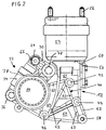
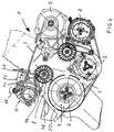
- An endless drive designated overall with 1 for the drive of not shown Auxiliary units 2 of an internal combustion engine schematically indicated in Figure 7 has a multi-groove V-ribbed belt 3. This runs from a pulley 4 on a crankshaft stump 6 of the internal combustion engine via a deflection roller 8 of a tensioning roller arrangement to a tensioning roller 10 and from this to the other, not shown auxiliary units 2 and these in turn on the pulley 4th
- the tensioning roller arrangement comprises a motor support 12 designed for the internal combustion engine Housing 14.
- An angle lever 18 is on a flange 16 of this housing 14 rotatably supported about a pivot point 20, at one of the ends 22, 24 of this angle lever 18 the tension roller 10 is rotatably mounted.
- a first leg extends between this pivot point 20 and the tensioning roller 10 28 of the angle lever 18 extends almost at right angles to the other End 24 towards a second leg 30.
- an elastic grip At this other end 24 an elastic grips Prestressed clamping element 32 in the form of a hydraulic tensioner 34 on this Angle lever.
- this tensioner 34 At the opposite end 36 of this tensioner 34, this is on a mounting eye 38 of the housing 14 pivotally supported.
- the motor support 12 has an integrally formed bearing flange 40 with a total of three Attachment points 42, 44, 46 through which a fixed connection by means of screws between this engine support 12 and an end face 48 of the crankcase 50 the internal combustion engine is provided.
- the motor support 12 carries a support flange almost perpendicular to this bearing flange 40 52, to which a bearing 54 formed separately from the internal combustion engine can be fastened is.
- This bearing 54 in turn has fastening means 56 for the body side Striking on.
- a carrying eye 60 is arranged for the transport of the internal combustion engine together with the tensioning roller arrangement.
- this carrying eye 60 can be a further, integral component of the motor support 12.
- the motor support 12 is designed as an aluminum die-cast part and has on it the Side facing the internal combustion engine has a wall 64 provided with ribs 62, 63 on.
- the leg 30 is with an integrally formed force application surface 66 equipped for fitting a form-fitting tool.
- this target 66 is a key-like tool in the assembly of the endless drive 1 Arranged arrow direction according to Figure 7 acting counterclockwise, so that the Tensioning roller 10 pivoting about the pivot point 20 of the angle lever 18 in FIG is pivoted to the right. As a result, the winding of the endless drive 1 is made considerably easier.
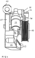
- the tension roller 10 is with a double-row ball bearing 70 on one by means of a Screw 72 supported on the angle lever 18 fixed inner pot 74.
- the Pivot point 20 of the angle lever 18 is guided by a inside a clamping sleeve 76 Screw 78 passes through, one according to Figure 6 on the left and right Washer 80 is arranged.
- Tensioner 34 is interposed with an elastic decoupling 82 and hinged on the angle lever 18 by means of a sleeve 84. In corresponding The other eye 86 of the tensioner 34 is fixed on the motor support 12.
- the support flange 52 has a groove-like recess 88 and a centrally arranged therein Through opening 90 for a fastener, not shown, associated with the bearing 54 Mistake.
- the tensioner 34 together with that provided by the comparatively large dimension Disks, such as pulley 4, deflection roller 8 and tensioning roller 10, require large wrap angles for an extended service life of the entire endless drive 1.
Landscapes
- Engineering & Computer Science (AREA)
- General Engineering & Computer Science (AREA)
- Mechanical Engineering (AREA)
- Chemical & Material Sciences (AREA)
- Combustion & Propulsion (AREA)
- Devices For Conveying Motion By Means Of Endless Flexible Members (AREA)
Applications Claiming Priority (2)
| Application Number | Priority Date | Filing Date | Title |
|---|---|---|---|
| DE19831864 | 1998-07-16 | ||
| DE1998131864 DE19831864A1 (de) | 1998-07-16 | 1998-07-16 | Spannrollenanordnung für einen Endlostrieb an einer Brennkraftmaschine |
Publications (2)
| Publication Number | Publication Date |
|---|---|
| EP0972920A2 true EP0972920A2 (fr) | 2000-01-19 |
| EP0972920A3 EP0972920A3 (fr) | 2001-01-10 |
Family
ID=7874186
Family Applications (1)
| Application Number | Title | Priority Date | Filing Date |
|---|---|---|---|
| EP99107237A Withdrawn EP0972920A3 (fr) | 1998-07-16 | 1999-04-14 | Roue de tension pour un dispositif d'entrainement sans fin pour un moteur à combustion interne |
Country Status (2)
| Country | Link |
|---|---|
| EP (1) | EP0972920A3 (fr) |
| DE (1) | DE19831864A1 (fr) |
Cited By (3)
| Publication number | Priority date | Publication date | Assignee | Title |
|---|---|---|---|---|
| WO2008107249A1 (fr) * | 2007-03-06 | 2008-09-12 | Schaeffler Kg | Dispositif de serrage pour commande à éléments de traction |
| CN104005843A (zh) * | 2013-02-26 | 2014-08-27 | 通用汽车环球科技运作有限责任公司 | 用于改善的拉伸带安装的发动机配件安装座 |
| CN104919213A (zh) * | 2013-01-30 | 2015-09-16 | 康明斯知识产权公司 | 用于带张紧器的间隔件 |
Families Citing this family (1)
| Publication number | Priority date | Publication date | Assignee | Title |
|---|---|---|---|---|
| DE102004049295B4 (de) * | 2004-10-09 | 2013-04-11 | Bayerische Motoren Werke Aktiengesellschaft | Spannrollenanordnung für einen Endlostrieb an einer Brennkraftmaschine, insbesondere Linearspanner für Keilrippenriemen |
Family Cites Families (6)
| Publication number | Priority date | Publication date | Assignee | Title |
|---|---|---|---|---|
| DE550086C (de) * | 1929-09-04 | 1932-05-12 | Colin Hugh Macmillan | Kettenspannvorrichtung fuer Brennkraftmaschinen |
| DE3341119C1 (de) * | 1983-11-12 | 1985-06-20 | Dr.Ing.H.C. F. Porsche Ag, 7000 Stuttgart | Tragarm fuer eine Brennkraftmaschine |
| DE3814525A1 (de) * | 1987-05-05 | 1988-11-17 | Volkswagen Ag | Spannsystem |
| DE3822055A1 (de) * | 1988-06-30 | 1990-01-04 | Porsche Ag | Haltevorrichtung |
| DE4012585A1 (de) * | 1990-04-20 | 1991-10-24 | Bayerische Motoren Werke Ag | Abstuetzvorrichtung fuer eine maschine, insbesondere brennkraftmaschine |
| DE19741449A1 (de) * | 1997-09-19 | 1999-03-25 | Volkswagen Ag | Stützkonsole für eine Brennkraftmaschine |
-
1998
- 1998-07-16 DE DE1998131864 patent/DE19831864A1/de not_active Withdrawn
-
1999
- 1999-04-14 EP EP99107237A patent/EP0972920A3/fr not_active Withdrawn
Cited By (5)
| Publication number | Priority date | Publication date | Assignee | Title |
|---|---|---|---|---|
| WO2008107249A1 (fr) * | 2007-03-06 | 2008-09-12 | Schaeffler Kg | Dispositif de serrage pour commande à éléments de traction |
| CN104919213A (zh) * | 2013-01-30 | 2015-09-16 | 康明斯知识产权公司 | 用于带张紧器的间隔件 |
| CN104919213B (zh) * | 2013-01-30 | 2017-08-01 | 康明斯知识产权公司 | 用于带张紧器的间隔件 |
| CN104005843A (zh) * | 2013-02-26 | 2014-08-27 | 通用汽车环球科技运作有限责任公司 | 用于改善的拉伸带安装的发动机配件安装座 |
| CN104005843B (zh) * | 2013-02-26 | 2017-06-13 | 通用汽车环球科技运作有限责任公司 | 用于改善的拉伸带安装的发动机配件安装座 |
Also Published As
| Publication number | Publication date |
|---|---|
| DE19831864A1 (de) | 2000-01-20 |
| EP0972920A3 (fr) | 2001-01-10 |
Similar Documents
| Publication | Publication Date | Title |
|---|---|---|
| EP0858563B1 (fr) | Dispositif de serrage dote d'un palier a friction conique et destine a des moyens de traction | |
| DE3590411C2 (de) | Riemenspannvorrichtung | |
| DE102006003207B4 (de) | Gehäusedeckelanordnung | |
| DE4300178C1 (de) | Riemenspannvorrichtung | |
| EP3431815B1 (fr) | Dispositif de tension de courroie | |
| EP2573423A1 (fr) | Tendeur de courroie pour entrainement par courroie et arrangement de machine avec tendeur de courroie | |
| DE102014008019B4 (de) | Spannvorrichtung für einen Nockenwellen-Nockenwellen-Kettentrieb | |
| EP1585912B1 (fr) | Unite modulaire munie d'un manchon pour transmission par chaine | |
| DE102008026064B4 (de) | Riemenspanneranordnung für einen Riementrieb | |
| DE102007050204A1 (de) | Spannvorrichtung für einen Zugmitteltrieb | |
| DE102005004541A1 (de) | Vorrichtung zum Einstellen der Riemenspannung | |
| EP0809041A2 (fr) | Dispositif d'équilibrage de torsion inertiel des moteurs à combustion interne | |
| DE10003208B4 (de) | Umlenk- oder Spannrolle für den Riementrieb einer Brennkraftmaschine | |
| DE19623485B4 (de) | Riemenspanner | |
| EP0972920A2 (fr) | Roue de tension pour un dispositif d'entrainement sans fin pour un moteur à combustion interne | |
| DE3322769C2 (de) | Vorrichtung zum Spannen eines beidseitig gezahnten Zahnriemens an einem Riemengetriebe | |
| DE3546901C2 (de) | Automatische Riemenspannvorrichtung | |
| DE102004041044A1 (de) | Drehpunktlagerung eines Aggregates | |
| DE10312514A1 (de) | Zugmitteltrieb | |
| DE19606002C2 (de) | Spann- oder Gleitschiene für Kettentriebe von Brennkraftmaschinen | |
| DE3626530C1 (de) | Anordnung eines Aggregates mittels der Verschraubung eines hochbelasteten Maschinenteils,insbesondere bei Brennkraftmaschinen | |
| DE19907668A1 (de) | Riementrieb | |
| EP1420193B1 (fr) | Tendeur d' entraînement pour courroie d' accessoires | |
| DE10028220A1 (de) | Riementrieb mit Spannrolle | |
| DE102005031294A1 (de) | Zugmitteltrieb eines Verbrennungskolbenmotors |
Legal Events
| Date | Code | Title | Description |
|---|---|---|---|
| PUAI | Public reference made under article 153(3) epc to a published international application that has entered the european phase |
Free format text: ORIGINAL CODE: 0009012 |
|
| AK | Designated contracting states |
Kind code of ref document: A2 Designated state(s): DE ES FR GB IT SE |
|
| AX | Request for extension of the european patent |
Free format text: AL;LT;LV;MK;RO;SI |
|
| PUAL | Search report despatched |
Free format text: ORIGINAL CODE: 0009013 |
|
| AK | Designated contracting states |
Kind code of ref document: A3 Designated state(s): AT BE CH CY DE DK ES FI FR GB GR IE IT LI LU MC NL PT SE |
|
| AX | Request for extension of the european patent |
Free format text: AL;LT;LV;MK;RO;SI |
|
| 17P | Request for examination filed |
Effective date: 20010710 |
|
| AKX | Designation fees paid |
Free format text: DE ES FR GB IT SE |
|
| STAA | Information on the status of an ep patent application or granted ep patent |
Free format text: STATUS: THE APPLICATION IS DEEMED TO BE WITHDRAWN |
|
| 18D | Application deemed to be withdrawn |
Effective date: 20021101 |