EP0972971A2 - Steuerung für Kraftfahrzeug-Automatikgetriebe, insbesondere mit Bestimmung des Fahrwiderstandes - Google Patents
Steuerung für Kraftfahrzeug-Automatikgetriebe, insbesondere mit Bestimmung des Fahrwiderstandes Download PDFInfo
- Publication number
- EP0972971A2 EP0972971A2 EP99114029A EP99114029A EP0972971A2 EP 0972971 A2 EP0972971 A2 EP 0972971A2 EP 99114029 A EP99114029 A EP 99114029A EP 99114029 A EP99114029 A EP 99114029A EP 0972971 A2 EP0972971 A2 EP 0972971A2
- Authority
- EP
- European Patent Office
- Prior art keywords
- vehicle
- driving force
- slope
- control unit
- value
- Prior art date
- Legal status (The legal status is an assumption and is not a legal conclusion. Google has not performed a legal analysis and makes no representation as to the accuracy of the status listed.)
- Granted
Links
Images














Classifications
-
- F—MECHANICAL ENGINEERING; LIGHTING; HEATING; WEAPONS; BLASTING
- F16—ENGINEERING ELEMENTS AND UNITS; GENERAL MEASURES FOR PRODUCING AND MAINTAINING EFFECTIVE FUNCTIONING OF MACHINES OR INSTALLATIONS; THERMAL INSULATION IN GENERAL
- F16H—GEARING
- F16H61/00—Control functions within control units of change-speed- or reversing-gearings for conveying rotary motion ; Control of exclusively fluid gearing, friction gearing, gearings with endless flexible members or other particular types of gearing
- F16H61/66—Control functions within control units of change-speed- or reversing-gearings for conveying rotary motion ; Control of exclusively fluid gearing, friction gearing, gearings with endless flexible members or other particular types of gearing specially adapted for continuously variable gearings
- F16H61/662—Control functions within control units of change-speed- or reversing-gearings for conveying rotary motion ; Control of exclusively fluid gearing, friction gearing, gearings with endless flexible members or other particular types of gearing specially adapted for continuously variable gearings with endless flexible members
- F16H61/66254—Control functions within control units of change-speed- or reversing-gearings for conveying rotary motion ; Control of exclusively fluid gearing, friction gearing, gearings with endless flexible members or other particular types of gearing specially adapted for continuously variable gearings with endless flexible members controlling of shifting being influenced by a signal derived from the engine and the main coupling
-
- B—PERFORMING OPERATIONS; TRANSPORTING
- B60—VEHICLES IN GENERAL
- B60K—ARRANGEMENT OR MOUNTING OF PROPULSION UNITS OR OF TRANSMISSIONS IN VEHICLES; ARRANGEMENT OR MOUNTING OF PLURAL DIVERSE PRIME-MOVERS IN VEHICLES; AUXILIARY DRIVES FOR VEHICLES; INSTRUMENTATION OR DASHBOARDS FOR VEHICLES; ARRANGEMENTS IN CONNECTION WITH COOLING, AIR INTAKE, GAS EXHAUST OR FUEL SUPPLY OF PROPULSION UNITS IN VEHICLES
- B60K28/00—Safety devices for propulsion-unit control, specially adapted for, or arranged in, vehicles, e.g. preventing fuel supply or ignition in the event of potentially dangerous conditions
- B60K28/10—Safety devices for propulsion-unit control, specially adapted for, or arranged in, vehicles, e.g. preventing fuel supply or ignition in the event of potentially dangerous conditions responsive to conditions relating to the vehicle
- B60K28/16—Safety devices for propulsion-unit control, specially adapted for, or arranged in, vehicles, e.g. preventing fuel supply or ignition in the event of potentially dangerous conditions responsive to conditions relating to the vehicle responsive to, or preventing, spinning or skidding of wheels
- B60K28/165—Safety devices for propulsion-unit control, specially adapted for, or arranged in, vehicles, e.g. preventing fuel supply or ignition in the event of potentially dangerous conditions responsive to conditions relating to the vehicle responsive to, or preventing, spinning or skidding of wheels acting on elements of the vehicle drive train other than the propulsion unit and brakes, e.g. transmission, clutch, differential
-
- F—MECHANICAL ENGINEERING; LIGHTING; HEATING; WEAPONS; BLASTING
- F16—ENGINEERING ELEMENTS AND UNITS; GENERAL MEASURES FOR PRODUCING AND MAINTAINING EFFECTIVE FUNCTIONING OF MACHINES OR INSTALLATIONS; THERMAL INSULATION IN GENERAL
- F16H—GEARING
- F16H61/00—Control functions within control units of change-speed- or reversing-gearings for conveying rotary motion ; Control of exclusively fluid gearing, friction gearing, gearings with endless flexible members or other particular types of gearing
- F16H61/02—Control functions within control units of change-speed- or reversing-gearings for conveying rotary motion ; Control of exclusively fluid gearing, friction gearing, gearings with endless flexible members or other particular types of gearing characterised by the signals used
- F16H61/0202—Control functions within control units of change-speed- or reversing-gearings for conveying rotary motion ; Control of exclusively fluid gearing, friction gearing, gearings with endless flexible members or other particular types of gearing characterised by the signals used the signals being electric
- F16H61/0204—Control functions within control units of change-speed- or reversing-gearings for conveying rotary motion ; Control of exclusively fluid gearing, friction gearing, gearings with endless flexible members or other particular types of gearing characterised by the signals used the signals being electric for gearshift control, e.g. control functions for performing shifting or generation of shift signal
- F16H61/0213—Control functions within control units of change-speed- or reversing-gearings for conveying rotary motion ; Control of exclusively fluid gearing, friction gearing, gearings with endless flexible members or other particular types of gearing characterised by the signals used the signals being electric for gearshift control, e.g. control functions for performing shifting or generation of shift signal characterised by the method for generating shift signals
-
- B—PERFORMING OPERATIONS; TRANSPORTING
- B60—VEHICLES IN GENERAL
- B60W—CONJOINT CONTROL OF VEHICLE SUB-UNITS OF DIFFERENT TYPE OR DIFFERENT FUNCTION; CONTROL SYSTEMS SPECIALLY ADAPTED FOR HYBRID VEHICLES; ROAD VEHICLE DRIVE CONTROL SYSTEMS FOR PURPOSES NOT RELATED TO THE CONTROL OF A PARTICULAR SUB-UNIT
- B60W50/00—Details of control systems for road vehicle drive control not related to the control of a particular sub-unit, e.g. process diagnostic or vehicle driver interfaces
- B60W2050/0001—Details of the control system
- B60W2050/0019—Control system elements or transfer functions
- B60W2050/0022—Gains, weighting coefficients or weighting functions
-
- B—PERFORMING OPERATIONS; TRANSPORTING
- B60—VEHICLES IN GENERAL
- B60W—CONJOINT CONTROL OF VEHICLE SUB-UNITS OF DIFFERENT TYPE OR DIFFERENT FUNCTION; CONTROL SYSTEMS SPECIALLY ADAPTED FOR HYBRID VEHICLES; ROAD VEHICLE DRIVE CONTROL SYSTEMS FOR PURPOSES NOT RELATED TO THE CONTROL OF A PARTICULAR SUB-UNIT
- B60W50/00—Details of control systems for road vehicle drive control not related to the control of a particular sub-unit, e.g. process diagnostic or vehicle driver interfaces
- B60W2050/0001—Details of the control system
- B60W2050/0019—Control system elements or transfer functions
- B60W2050/0028—Mathematical models, e.g. for simulation
-
- B—PERFORMING OPERATIONS; TRANSPORTING
- B60—VEHICLES IN GENERAL
- B60W—CONJOINT CONTROL OF VEHICLE SUB-UNITS OF DIFFERENT TYPE OR DIFFERENT FUNCTION; CONTROL SYSTEMS SPECIALLY ADAPTED FOR HYBRID VEHICLES; ROAD VEHICLE DRIVE CONTROL SYSTEMS FOR PURPOSES NOT RELATED TO THE CONTROL OF A PARTICULAR SUB-UNIT
- B60W50/00—Details of control systems for road vehicle drive control not related to the control of a particular sub-unit, e.g. process diagnostic or vehicle driver interfaces
- B60W2050/0001—Details of the control system
- B60W2050/0019—Control system elements or transfer functions
- B60W2050/0028—Mathematical models, e.g. for simulation
- B60W2050/0031—Mathematical model of the vehicle
-
- B—PERFORMING OPERATIONS; TRANSPORTING
- B60—VEHICLES IN GENERAL
- B60W—CONJOINT CONTROL OF VEHICLE SUB-UNITS OF DIFFERENT TYPE OR DIFFERENT FUNCTION; CONTROL SYSTEMS SPECIALLY ADAPTED FOR HYBRID VEHICLES; ROAD VEHICLE DRIVE CONTROL SYSTEMS FOR PURPOSES NOT RELATED TO THE CONTROL OF A PARTICULAR SUB-UNIT
- B60W50/00—Details of control systems for road vehicle drive control not related to the control of a particular sub-unit, e.g. process diagnostic or vehicle driver interfaces
- B60W2050/0001—Details of the control system
- B60W2050/0043—Signal treatments, identification of variables or parameters, parameter estimation or state estimation
- B60W2050/0057—Frequency analysis, spectral techniques or transforms
-
- B—PERFORMING OPERATIONS; TRANSPORTING
- B60—VEHICLES IN GENERAL
- B60W—CONJOINT CONTROL OF VEHICLE SUB-UNITS OF DIFFERENT TYPE OR DIFFERENT FUNCTION; CONTROL SYSTEMS SPECIALLY ADAPTED FOR HYBRID VEHICLES; ROAD VEHICLE DRIVE CONTROL SYSTEMS FOR PURPOSES NOT RELATED TO THE CONTROL OF A PARTICULAR SUB-UNIT
- B60W2530/00—Input parameters relating to vehicle conditions or values, not covered by groups B60W2510/00 or B60W2520/00
- B60W2530/16—Driving resistance
-
- B—PERFORMING OPERATIONS; TRANSPORTING
- B60—VEHICLES IN GENERAL
- B60W—CONJOINT CONTROL OF VEHICLE SUB-UNITS OF DIFFERENT TYPE OR DIFFERENT FUNCTION; CONTROL SYSTEMS SPECIALLY ADAPTED FOR HYBRID VEHICLES; ROAD VEHICLE DRIVE CONTROL SYSTEMS FOR PURPOSES NOT RELATED TO THE CONTROL OF A PARTICULAR SUB-UNIT
- B60W2552/00—Input parameters relating to infrastructure
- B60W2552/15—Road slope, i.e. the inclination of a road segment in the longitudinal direction
-
- B—PERFORMING OPERATIONS; TRANSPORTING
- B60—VEHICLES IN GENERAL
- B60W—CONJOINT CONTROL OF VEHICLE SUB-UNITS OF DIFFERENT TYPE OR DIFFERENT FUNCTION; CONTROL SYSTEMS SPECIALLY ADAPTED FOR HYBRID VEHICLES; ROAD VEHICLE DRIVE CONTROL SYSTEMS FOR PURPOSES NOT RELATED TO THE CONTROL OF A PARTICULAR SUB-UNIT
- B60W2710/00—Output or target parameters relating to a particular sub-units
- B60W2710/10—Change speed gearings
- B60W2710/105—Output torque
-
- F—MECHANICAL ENGINEERING; LIGHTING; HEATING; WEAPONS; BLASTING
- F16—ENGINEERING ELEMENTS AND UNITS; GENERAL MEASURES FOR PRODUCING AND MAINTAINING EFFECTIVE FUNCTIONING OF MACHINES OR INSTALLATIONS; THERMAL INSULATION IN GENERAL
- F16H—GEARING
- F16H59/00—Control inputs to control units of change-speed- or reversing-gearings for conveying rotary motion
- F16H59/02—Selector apparatus
- F16H59/08—Range selector apparatus
- F16H2059/082—Range selector apparatus for different transmission modes
-
- F—MECHANICAL ENGINEERING; LIGHTING; HEATING; WEAPONS; BLASTING
- F16—ENGINEERING ELEMENTS AND UNITS; GENERAL MEASURES FOR PRODUCING AND MAINTAINING EFFECTIVE FUNCTIONING OF MACHINES OR INSTALLATIONS; THERMAL INSULATION IN GENERAL
- F16H—GEARING
- F16H59/00—Control inputs to control units of change-speed- or reversing-gearings for conveying rotary motion
- F16H59/14—Inputs being a function of torque or torque demand
- F16H2059/142—Inputs being a function of torque or torque demand of driving resistance calculated from weight, slope, or the like
-
- F—MECHANICAL ENGINEERING; LIGHTING; HEATING; WEAPONS; BLASTING
- F16—ENGINEERING ELEMENTS AND UNITS; GENERAL MEASURES FOR PRODUCING AND MAINTAINING EFFECTIVE FUNCTIONING OF MACHINES OR INSTALLATIONS; THERMAL INSULATION IN GENERAL
- F16H—GEARING
- F16H59/00—Control inputs to control units of change-speed- or reversing-gearings for conveying rotary motion
- F16H59/60—Inputs being a function of ambient conditions
- F16H59/66—Road conditions, e.g. slope, slippery
- F16H2059/663—Road slope
-
- F—MECHANICAL ENGINEERING; LIGHTING; HEATING; WEAPONS; BLASTING
- F16—ENGINEERING ELEMENTS AND UNITS; GENERAL MEASURES FOR PRODUCING AND MAINTAINING EFFECTIVE FUNCTIONING OF MACHINES OR INSTALLATIONS; THERMAL INSULATION IN GENERAL
- F16H—GEARING
- F16H59/00—Control inputs to control units of change-speed- or reversing-gearings for conveying rotary motion
- F16H59/48—Inputs being a function of acceleration
-
- F—MECHANICAL ENGINEERING; LIGHTING; HEATING; WEAPONS; BLASTING
- F16—ENGINEERING ELEMENTS AND UNITS; GENERAL MEASURES FOR PRODUCING AND MAINTAINING EFFECTIVE FUNCTIONING OF MACHINES OR INSTALLATIONS; THERMAL INSULATION IN GENERAL
- F16H—GEARING
- F16H59/00—Control inputs to control units of change-speed- or reversing-gearings for conveying rotary motion
- F16H59/50—Inputs being a function of the status of the machine, e.g. position of doors or safety belts
- F16H59/58—Inputs being a function of the status of the machine, e.g. position of doors or safety belts dependent on signals from the steering
-
- F—MECHANICAL ENGINEERING; LIGHTING; HEATING; WEAPONS; BLASTING
- F16—ENGINEERING ELEMENTS AND UNITS; GENERAL MEASURES FOR PRODUCING AND MAINTAINING EFFECTIVE FUNCTIONING OF MACHINES OR INSTALLATIONS; THERMAL INSULATION IN GENERAL
- F16H—GEARING
- F16H59/00—Control inputs to control units of change-speed- or reversing-gearings for conveying rotary motion
- F16H59/60—Inputs being a function of ambient conditions
- F16H59/66—Road conditions, e.g. slope, slippery
Definitions
- This invention relates to a control system for an automatic vehicle transmission, more particularly to a control system for an automatic vehicle transmission, that controls the gear ratio (speed ratio) or driving force so as to reflect the intention of the vehicle operator in the vehicle operation as closely as possible.
- the conventional technologies do not take into account the slope or other such running conditions and environmental factors. Since they therefore do not reflect driving force change produced by change in running resistance in the case of a slope or the like, they cannot vary the driving force in response to the running state.
- One object of the invention is to provide a control system for an automatic vehicle transmission that, focusing on the fact that the quality of drivability varies markedly during hill climbing and descent, estimates the slope, discriminates climbing, descending and other driving states, and controls the gear ratio (speed ratio) in response to the discrimination so as to achieve the desired driving force and enhance drivability.
- Another object of the invention is to provide a control system for an automatic vehicle transmission that calculates an evaluation indicator signifying drivability tendency and controls the gear ratio (speed ratio) in response to the calculated evaluation indicator, thereby enhancing drivability.
- Still another object of the invention is to provide a control system for an automatic vehicle transmission that estimates the road slope accurately, without estimation lag, and controls the gear ratio (speed ratio) optimally, thereby enhancing drivability.
- a system for controlling an automatic transmission of a vehicle having an input shaft connected to an internal combustion engine mounted on the vehicle and an output shaft connected to driven wheels of the vehicle, the transmission transmitting output torque generated by the engine and inputted through the input shaft to the driven wheels through the output shaft
- the improvement comprises: operating condition detecting means for detecting operating conditions of the engine and the vehicle including at least a vehicle speed and a throttle opening; running resistance calculating means for calculating a running resistance acting on the vehicle;driving force calculating means for calculating a driving force generated by the vehicle; slope estimating means for estimating a slope of a road on which the vehicle travels based on at least the calculated running resistance and the driving force; running state discriminating means for comparing the estimated slope with a predetermined value and for discriminating a running state of the vehicle; gear ratio determining means for calculating a maximum driving force to be generated by the vehicle at a current gear ratio to calculate a driving force difference from the calculated driving force
- a system for controlling an automatic transmission of a vehicle having an input shaft connected to an internal combustion engine mounted on the vehicle and an output shaft connected to driven wheels of the vehicle, the transmission transmitting output torque generated by the engine and inputted through the input shaft to the driven wheels through the output shaft
- the improvement comprises:operating condition detecting means for detecting operating conditions of the engine and the vehicle including at least a vehicle speed and a throttle opening; actual driving force calculating means for calculating an actual driving force generated by the vehicle based on at least the detected throttle opening; operator desired estimating means for estimating an operator desire estimated value desired by a vehicle operator based on at least the detected throttle opening; indicator conversion means for converting the actual driving force and the operator desire estimated value to an evaluation indictor; running characteristic discriminating means for discriminating based on the evaluation indicator which of a first running characteristic and a second running characteristic, which are different in driving force response, the vehicle operator wants; and driving force controlling means for controlling a driving force of the vehicle through
- FIG 1 is an overall schematic view of a control system for an automatic vehicle transmission according to the invention.
- the automatic transmission in the illustrated embodiment is a belt-drive continuously variable transmission (CVT).
- CVT continuously variable transmission
- Reference numeral 10 in this figure designates an internal combustion engine, more precisely the main unit of the engine. This unit is referred to both as the “engine” and as the “engine main unit” in the following description.
- a throttle valve 14 is installed in an air intake pipe 12 connected to the engine 10. The throttle valve 14 is operated by an accelerator pedal 16 located on the floor of the vehicle near the operator's seat (not shown), not by direct mechanical connection but indirectly by the output of a stepper motor 18 connected therewith.
- the output shaft (crankshaft) 20 of the engine (main unit) 10 is connected to a continuously variable transmission (CVT) 24.
- CVT continuously variable transmission
- the output shaft 20 of the engine (main unit) 10 is connected through a dual-mass flywheel 26 to an input shaft 28 of the transmission 24.
- the engine (main unit) 10 and the transmission 24 are installed in a vehicle represented solely by the reference numeral 29.
- the transmission 24 comprises a metal V-belt mechanism 32 located between the input shaft 28 and a countershaft 30, a planetary gear-type forward/reverse switching mechanism 36 located between the input shaft 28 and a drive-side movable pulley 34, and a start clutch 42 located between the countershaft 30 and a differential 40.
- Driving power transmitted to the differential 40 is transmitted to left and right driven wheels (not shown) through a drive shaft (not shown).
- the metal V-belt mechanism 32 comprises the drive-side movable pulley 34 mounted on the input shaft 28, a driven-side movable pulley 46 mounted on the countershaft 30, and a metal V-belt 48 wound about the two pulleys.
- the drive-side movable pulley 34 comprises a fixed pulley half 50 mounted on the input shaft 28 and a movable pulley half 52 movable relative to the fixed pulley half 50 in the axial direction.
- a drive-side cylinder chamber 54 enclosed by a cylinder wall 50a connected to the fixed pulley half 50.
- Oil pressure supplied to the drive-side cylinder chamber 54 through an oil line 54a produces lateral pressure for moving the movable pulley half 52 in the axial direction.
- the driven-side movable pulley 46 comprises a fixed pulley half 56 mounted on the countershaft 30 and a movable pulley half 58 movable relative to the fixed pulley half 56 in the axial direction.
- On the side of the movable pulley half 58 is formed a driven-side cylinder chamber 60 enclosed by a cylinder wall 56a connected to the fixed pulley half 56. Oil pressure supplied to the driven-side cylinder chamber 60 through an oil line 60a produces lateral pressure for moving the movable pulley half 58 in the axial direction.
- a regulator valve group 64 is provided for determining pulley control oil pressure supplied to the drive-side cylinder chamber 54 and the driven-side cylinder chamber 60, and a speed-ratio control valve group 66 is provided for supplying the pulley control oil pressure to the cylinder chambers 54 and 60. These set appropriate lateral pulley pressures at which no V-belt 48 slip occurs and vary the pulley width of the pulleys 34, 46 to vary the radius of the V-belt 48 wound about the pulleys 34, 46, thereby continuously varying the speed ratio.
- the planetary gear-type forward/reverse switching mechanism 36 comprises a sun gear 68 connected to the input shaft 28, a carrier 70 connected to the fixed pulley half 50, a ring gear 74 that can be immobilized by a reverse brake 72, and a forward clutch 76 that can connect the sun gear 68 and the carrier 70.
- the start clutch 42 is for ON/OFF (engage/disengage) control of power transmission between the countershaft 30 and the differential 40.
- the start clutch 42 When the start clutch 42 is ON (engaged), the engine output varied in speed ratio by the metal V-belt mechanism 32 is transmitted through gears 78, 80, 82 and 84 to the differential 40, which divides and transmits it to the left and right driven wheels (not shown).
- the start clutch 42 When the start clutch 42 is OFF (disengaged), the transmission assumes a neutral state.
- the operation of the start clutch 42 is controlled by a clutch control valve 88, and the operation of the reverse brake 72 and the forward clutch 76 of the forward/reverse switching mechanism 36 is controlled by a manual shift valve 90 in response to the operation of a manual shift lever (not shown).
- valve groups are controlled based on control signals from a transmission control unit 100 comprising of a microcomputer.
- a crank angle sensor 102 provided at an appropriate location in the engine main unit 10, such as near the cam shaft (not shown), outputs a signal proportional to the crank angle (which is counted and used to calculate the engine speed Ne).
- a manifold absolute pressure sensor 104 installed in the air intake pipe 12 at an appropriate location downstream of the throttle valve 14 outputs a signal proportional to the manifold absolute pressure PBA in the air intake pipe (the engine load).
- a coolant temperature sensor 106 provided at an appropriate location on the cylinder block (not shown) outputs a signal proportional to the engine coolant temperature TW.
- An intake air temperature sensor 107 provided an appropriate location on the air intake pipe 12 outputs a signal proportional to the intake air temperature (approximately equal to the outside air temperature).
- a throttle position sensor 108 installed near the throttle valve 14 outputs a signal proportional to the throttle opening ⁇ th and an accelerator position sensor 110 provided near the accelerator pedal 16 outputs a signal proportional to the accelerator position ACC to which the vehicle operator has depressed the accelerator pedal 16.
- a brake switch 112 provided near the brake pedal or the brake system (neither shown) outputs a brake ON signal in response to an operator braking operation.
- a speed sensor 114 provided near the input shaft 28 outputs a signal proportional to the rotational speed NDR of the input shaft 28
- a speed sensor 116 provided near the driven-side movable pulley 46 outputs a signal proportional to the rotational speed of the driven-side movable pulley 46, i.e., the rotational speed NDN of the input shaft of the start clutch 42 (the countershaft 30)
- a speed sensor 118 provided near the gear 78 outputs a signal proportional to the rotational speed of the gear 78, i.e., the rotational speed NOUT of the output shaft of the start clutch 42.
- a vehicle speed sensor 122 provided near the drive shaft (not shown) connected to the differential 40 outputs a signal proportional to the vehicle speed V.
- a shift lever position switch 124 provided in the vicinity of the shift lever (not shown) installed on the vehicle floor near the operator's seat outputs a signal proportional to one among from the various gear range positions (D, N, P ...) selected by the vehicle operator.
- An accelerometer 126 provided near the middle of the vehicle 29 outputs a signal proportional to the lateral acceleration G acting perpendicularly to the advancing direction of the vehicle 29.
- a steer angle sensor 128 provided near the steering wheel (not shown) installed at the operator's seat (not shown) outputs a signal corresponding to the steer angle.
- the system is also equipped with an engine control unit 200 which comprises of a microcomputer.
- the outputs of the crank angle sensor 102, the manifold absolute pressure sensor 104, the coolant temperature sensor 106 and the throttle position sensor 108 are forwarded to both of the control units 100 and 200.
- the system is also equipped with an integrated control unit 300 which comprises of a microcomputer.
- the outputs of the accelerator position sensor 110, the vehicle speed sensor 122 etc. are sent to the integrated control unit 300.
- the integrated control unit 300 determines the desired gear ratio (speed ratio), i.e., the desired value of the rotational speed NDR, and sends it to the transmission control unit 100.
- the transmission control unit 100 drives the movable pulleys 34, 46 to control the speed ratio and obtain the desired NDR.
- the desired NDR is the desired rotational speed of the drive-side movable pulley 34 of the transmission 24 and the gear ratio (speed ratio; hereinafter called simply "ratio") is solely determined and controlled by defining the desired NDR relative to the vehicle speed V.
- this embodiment is equipped with the transmission 24 capable of continuously controlling the ratio, it can, as explained in the following, enhance drivability by effecting control to optimize the ratio for the running state.
- the integrated control unit 300 also determines the desired throttle opening and sends it to a throttle control unit 400.
- the throttle control unit 400 drives the throttle valve 14 via the stepper motor 18 to set the throttle opening to the decided value.
- FIG. 2 is a flow chart showing the operation of the control system for automatic vehicle transmission according to the present invention. Before going into an explanation based on this figure, the operation of the control system will first be explained in general terms with reference to Figure 3.
- this system focuses on the fact that the quality of drivability varies markedly during hill climbing and descent. Vehicle running results were analyzed especially for mountain roads and the factors affecting drivability were analyzed in terms of physical quantity (driving force).
- the soascertained relationship between drivability and physical quantity is expressed as an evaluation indicator and the ratio (or driving force) is controlled based on the evaluation indicator.
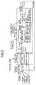
- the physical quantity state estimation model shown in Figure 3 is used to analyze correlation with drivability. More particularly, in a manipulated variable input section, the degree of operator desire is estimated based on the position of the accelerator pedal operated by the vehicle operator and expressed as an indicator. A model for this is shown in Figure 4.
- FIG. 4 One feature of the model shown in Figure 4 is that the accelerator pedal position and the brake pedal depression are viewed on the same plane. i.e., the model assumes release of the accelerator pedal to be a braking operation. Specifically, as shown in Figure 5, driving force (torque) is viewed as load value based on the estimated braking force (explained later). As shown in Figure 6, the gain is regulated based on the accelerator pedal-brake pedal foot transfer time. This will be explained later.
- the vehicle gain is estimated in the subject vehicle section of the model shown in Figure 3. Specifically, as shown in Figure 7, a model created to represent the difference between the ideal vehicle response and the actual vehicle response (the actual response of the subject vehicle 29) is used to synthesize the actual output and the operator's desired output. More specifically, the difference is calculated and the vehicle response (driving force) estimated. This will also be explained later.
- the indicators obtained from the model illustrated in Figure 4 and the model illustrated in Figure 7 are averaged and compared with a prescribed value to discriminate whether the operator wants sporty driving (running) characteristics or relaxed driving (running) characteristics.
- sporty driving (running) characteristics is meant high response of driving force change to accelerator pedal position.
- relaxed driving (running) characteristics is meant low response of driving force to accelerator pedal position as compared with the sporty driving (running) characteristics, i.e., characteristics that lower the degree of operator involvement.
- the driving condition is discriminated based on the slope estimated from the vehicle speed and the like, i.e., it is discriminated whether the vehicle is running uphill, downhill or level, and the ratio is controlled to bring the driving force to the desired value.
- the ratio is controlled to bring the driving force to the desired value by controlling the ratio to obtain higher driving force response than in the case of the relaxed driving characteristics.
- a ratio control output indicator is calculated to obtain a ratio coefficient (ratio multiplier) and a base (ratio) ratio map value is multiplied thereby to decide the ratio.
- the illustrated program is executed by the integrated control unit 300 at prescribed intervals, e.g., once every 0.1sec.
- the slope of the road traveled is calculated (estimated) so as to enable discrimination of the driving condition or running state. This is done either by “long-span slope estimation” or by “short-span slope estimation.” Long-span slope estimation is carried out over a long period with emphasis on precision and produces a “long-span estimated slope.” Short-span slope estimation is carried out in a short period with emphasis on response and produces a “short-span estimated slope.”
- the slope estimation is conducted using different filter time constants.
- One of the estimated slopes is selected in light of the vehicle running state, the driving environment is discriminated, and the ratio controlled.
- the processing for calculating the short-span estimated slope is carried out in S100 to S110.
- the detected vehicle speed V, acceleration dv (vehicle acceleration; first order difference value or differential value of the vehicle speed V), throttle opening ⁇ th, ratio (NDR) and the steering angle (lateral acceleration G) are read.
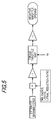
- Figure 9 is a diagram for explaining the processing of S100. As shown, the processing is conducted by use of a low-pass filter 500. Specifically, at the time the detected values are read they are filter-processed through the low-pass filter 500.
- the cut-off frequency of the low-pass filter 500 is set high and the attenuation characteristic is set low to raise the response.
- the cut-off frequency is set low and the attenuation characteristic is set high, i.e., the accuracy is increased by eliminating high-frequency components that include a lot of disturbance components attributable to acceleration/deceleration etc.
- the torque Te being output by the engine (main unit) 10 is calculated (estimated) from the detected throttle opening ⁇ th using an appropriately compiled throttle opening-torque conversion table (not shown).
- cornering resistance Rc is meant the decelerating force produced by tire deformation (turning force) during cornering.
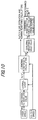
- Figure 10 is a block diagram for explaining the cornering resistance calculation.
- the input value of the steer angle is converted to an absolute value, and this absolute value and the detected vehicle speed are used as address data to retrieve the lateral acceleration G (acceleration acting in the lateral direction of the vehicle) from a lateral G map (not shown).
- the calculated lateral G and the detected vehicle speed are used as address data to retrieve the cornering resistance Rc from an appropriately created map (not shown).
- the accuracy of the running resistance R calculated (estimated) as explained later can be enhanced by addition of the cornering resistance Rc obtained here.
- a cornering resistance hold value is calculated for use in the mountain/town road discrimination explained later.
- the obtained value is defined as short-span estimated slope ⁇ short.
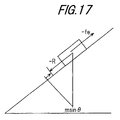
- Sin ⁇ is used as slope ⁇ because it would be difficult for the microcomputer to calculate slope ⁇ within the control cycle of 0.1sec, and such a calculation is in fact unnecessary.
- the inventors have found the short-span estimated slope value calculated in this manner to be accurate to within ⁇ 5°.
- the program goes to S118, in which the product of the short-span estimated slope value and the vehicle weight m is defined as the slope-specific resistance Rb during braking (during brake operation), and then to S120, in which the braking force Fbrk is calculated (estimated) by the equation set out in the drawing.
- the braking force can be determined as the deviation between the slope-specific driving force immediately before brake switch 112 turn-on and the slope-specific driving force during braking.
- the estimated slope value before braking ⁇ beforebrk is being held because it was found that the brake pedal was also being depressed in the preceding cycle.
- this held value is used to calculate the slope-specific resistance before braking msin ⁇ beforebrk , whereafter the calculated value is subtracted from the slope-specific resistance during braking msin ⁇ short calculated in S118 to determine the braking force Fbrk.
- the long-span estimated slope ⁇ long is calculated.
- the long-span estimated slope is calculated only when the vehicle is running normally with acceleration fluctuation at less than a prescribed value.
- the processing for calculating the long-span estimated slope is carried out in S136 to S146.
- the detected vehicle speed V, acceleration dv, throttle opening ⁇ th, ratio, and the steer angle (lateral acceleration G) are read.
- filtered sensor output values are read from the filter 500, whose cut-off frequency is set low and attenuation characteristic is set high.
- the processing in steps S138 to S144 is similar to that in the processing for calculating the short-span estimated slope and will not be explained again here.
- the value obtained in S146 is defined as estimated slope ⁇ long. The inventors have found the short-span estimated slope value calculatedin this manner to be accurateto within ⁇ 2°.
- one or the other of the short-span estimated slope and the long-span estimated slope is used according to purpose.
- the vehicle weight is calculated (estimated) by an appropriate method.
- the vehicle weight is stored in memory beforehand, the stored value is corrected to enhance its accuracy when the vehicle is running stably.
- the estimated slope value ⁇ is set to the long-span estimated slope value ⁇ long obtained in S146, whereafter the program goes to S128.
- the aforesaid estimated braking force Fbrk is convened to a negative throttle valve opening value by retrieval from a reverse torque map and the convened value is subtracted from the detected throttle opening.
- the estimated braking force is convened to driving force around the vehicle axle, the result is used to retrieve a throttle valve opening value from a map with characteristics opposite from those of the map used earlier to determine torque Te, and the retrieved value is convened to a negative value.
- the difference obtained is multiplied by P (proponional) gain, the obtained value is subjected to peak-holding and time-course attenuating, and the result is defined as operator desire (expressed as throttle opening ( ⁇ th)).
- the difference obtained (not shown) is multiplied by D (differential) gain, the obtained value is subjected to peak-holding and time-course attenuating, and the result is defined as degree of operator desire (expressed as amount of throttle opening change dth; more specifically, indicating amount of throttle opening change).
- the accelerator depression speed or foot transfer time indicates the intensity of the operator's desire.
- the D gain is therefore used to weight the differential value of the accelerator pedal position as a technique for reflecting this fact in the model. As shown in Figure 6, the D gain is varied as a function of the determined accelerator pedal-to-brake pedal transfer time.
- the vehicle driving force (of the subject vehicle 29, corresponding to the aforesaid vehicle gain) is estimated.
- FIG. 7 At the top of this drawing is shown a model depicting the ideal response of the vehicle (first model) and at the bottom is shown a model depicting the actual response of the vehicle (second model).
- the first model determines the driving force by the same arithmetic operations as shown in Figure 4, multiplies the result by the detected vehicle speed and defines the product as the output desired by the operator.
- the second model calculates the estimated driving force from the aforesaid engine torque Te, subtracts the estimated braking force from the result, similarly multiplies the difference by the detected vehicle speed and defines the product as the output actually being produced by the vehicle (actual output).
- the actual output is subtracted from the desired output in an adder/subtracter stage and the difference is defined as the divergence output (or difference output). This divergence output indicates how much divergence is present between the degree of operator desire and the actual output.
- an evaluation indicator that reflects the operator desire (desire for relaxed driving or sporty driving) in an indicator based on the performance of the vehicle engine.
- averaging is used as the synthesis method here, other methods, such as selection of the maximum value or the minimum value, can also be adopted.
- the averaging is not limited simple averaging but can instead be weighted averaging or the like.
- the reason for synthesizing the indicators of the estimated operator desire value and the estimated vehicle driving force value is that there are cases, such as during cruising on an expressway, when the throttle opening and the change therein are small but the driving force is large. As this is also highly sporty driving, the judgment of whether or not the operator desires sporty driving cannot be made solely from the throttle opening and change therein but must also take the estimated vehicle driving force into account.
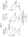
- “Instantaneous reserve drive force” is a term coined by the inventors. It refers to the difference between the wide-open output (the output at Wide-Open Throttle) that would be produced if the accelerator pedal should be fully depressed (or depressed a prescribed amount) at the current ratio and engine speed and the actual engine torque the engine is actually outputting at the current ratio and engine speed. As such, it is a parameter indicating the vehicle reserve or the state of driving force change with respect to accelerator pedal position (accelerator response). This is a different concept from “reserve power” (difference between wide-open output and running resistance) as generally defined.
- Figure 13 shows the control effected when the operator wants relaxed driving and the vehicle has been judged to be running uphill.
- the model shown at the top of the drawing is used to set the ratio so as to bring the instantaneous reserve drive force at the bottom of the drawing to the desired instantaneous reserve drive force.
- Tests conducted by the inventors showed that a desired instantaneous reserve drive force of a maximum acceleration of around 0. 1G, of wound 50 to 100kgf when the vehicle weight is about 1 [t], is suitable for relaxed uphill driving.
- the desired instantaneous reserve drive force can be made variable with the estimated driving condition indicator, so as to decrease as the estimated driving condition indicator increases, i.e., as the operator's desire for driving force declines, and also to vary with the vehicle speed V.
- the desired instantaneous reserve drive force is set to increase at low vehicle speed, when the speed adjustment capability required is greater than at high vehicle speed.
- the set ratio is convened to the aforesaid indicator on a scale of 1 to 5 points by an appropriate method.
- level driving control will now be explained.
- the quality of drivability does not vary as markedly during level driving as during hill ascent/descent.
- level driving control is effected to optimize fuel efficiency. This is achieved by utilizing the aforesaid Drive By Wire fashion (i.e., the stepper motor 18 and throttle control unit 400) to control the throttle valve opening and thereby control the driving force.
- the ratio is controlled with respect to the instantaneous reserve drive force to control the throttle opening with respect to the driving force desired by the operator.
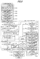
- Figure 18 is a subroutine flow chart of showing this control.
- the illustrated program is executed at prescribed intervals, e.g., once every 0.1sec.
- a summary of the control will be set out first.
- the driving force desired by the operator is compared with the actual driving force and the throttle is opened/closed by a prescribed amount according to the result of the comparison.
- the total efficiency ⁇ total of the engine and the transmission is calculated and compared with that in the preceding cycle.
- the efficiency has increased, then, if decreasing control of the desired instantaneous reserve drive force was effected in the preceding cycle, further decreasing-control is effected on the assumption that continuing the control in the decrease direction will further improve the efficiency.
- the ratio seeks higher gear levels.
- the control is switched to increasing control. If the efficiency turns up, the increase direction is continued.
- the total efficiency change and the desired instantaneous reserve drive force control direction are discriminated and control is effected to achieve a high total efficiency.
- S180 it is checked whether level driving fuel economy control is currently in effect.
- the program goes to S182, in which it is checked whether the actual driving force is smaller than the driving force desired by the operator.
- the program goes to S184, in which a prescribed value tha is added to the current throttle opening ⁇ th and the throttle valve 14 is controlled in the opening direction to obtain the sum value.
- the desired instantaneous reserve drive force (designated "Fie-obj") is reduced toward zero by a prescribed amount.
- the program then goes to S190, in which, first, the efficiency ⁇ eng of the engine 10 and the efficiency ⁇ tm of the transmission 24 are calculated.
- the engine efficiency ⁇ eng and the transmission efficiency ⁇ tm are determined by map retrieval. More specifically, the engine efficiency ⁇ eng is retrieved from an optimum fuel efficiency map mapped as a function of the torque Te (calculated in S102) and the engine speed Ne. The transmission efficiency ⁇ tm is retrieved from an optimum fuel efficiency map mapped as a function of the aforesaid NDR and NDN.
- the total efficiency ⁇ total is then calculated as the product of the retrieved engine efficiency ⁇ eng and transmission efficiency ⁇ tm and the value in the preceding cycle old ⁇ total is updated by overwriting it with the calculated value (current value).
- the preceding value is appropriately set to, for example, zero.
- the total efficiency ⁇ total indicates the engine and transmission efficiency in terms of fuel economy.
- S194 it is checked whether the current value (calculated value) is greater than the preceding value.
- the program goes to S195, in which it is checked whether sequential incrementing control of the desired instantaneous reserve drive force (S196) was effected in the preceding cycle.
- S195 the program goes to S196, in which a prescribed value x is added to the desired instantaneous reserve drive force, and when NO, the program goes to S197, in which the prescribed value x is subtracted from the desired instantaneous reserve drive force.
- the desired instantaneous reserve drive force can be controlled to maximize ⁇ total. Specifically, as shown in Figure 19, by increasing/decreasing the desired instantaneous reserve drive force it can be brought to and trapped at the desired instantaneous reserve drive force value F ⁇ max at which the total efficiency is optimum in terms of fuel economy.
- the substraction of the prescribed value from the desired instantaneous reserve drive force value amounts to controlling the driving force by shifting the ratio of the transmission toward the high ratio side by an amount corresponding to the prescribed amount x and the addition of the prescribed value to the desired instantaneous reserve drive force value amounts to controling the driving force by shifting the ratio of the transmission toward the low ratio side by an amount corresponding to the prescribed amount x .
- the optimum point can, at a substantially constant transmission transfer efficiency, be achieved by shifting the desired instantaneous reserve drive force value toward zero. As shown in Figure 19, therefore, the fuel economy can be optimized by trapping the desired instantaneous reserve drive force value at the optimum point F ⁇ max.
- the obtained ratio is converted to a ratio control output indicator, whereafter, in S40, the obtained indicator is applied to the vertical axis of the illustrated characteristics to determine a ratio coefficient (ratio multiplier) on the horizontal axis.
- the base (ratio) map value (retrieved using the throttle opening and the vehicle speed as address data) is multiplied by the obtained ratio multiplier to determine the ratio.
- this processing is for discriminating road slipperiness and effecting ratio control based thereon. Specifically, multiple road conditions are discriminated and ratio control is carried based on the result.
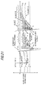
- Figure 20 is a subroutine flow chart for explaining the processing of S126 and Figure 21 is a graph representing change in slope-specific driving force with road condition.
- the estimated slope-specific driving force calculated earlier is subjected to peak-holding and time-course decrementing. More specifically, the estimated slope-specific driving force is held, a prescribed amount is subtracted therefrom every program cycle, and when a larger value is calculated, it overwrites the existing value.
- the value output by the intake air temperature sensor 107 is read as corresponding to the outside air temperature.
- the specified value is appropriately set to enable discrimination of icy road condition.
- the program goes to S210, in which the road is determined to be icy and instantaneous reserve drive force control for icy road is conducted.
- the result in S208 is NO, it is judged that the vehicle is running on a dirt road with very poor traction and the program goes to S212, in which instantaneous reserve drive force control for bad road is conducted.
- the processing in S212 etc. will be explained.
- the current vehicle speed V is used to retrieve the desired instantaneous reserve drive force from preestablished characteristics.
- Figure 23 is a graph showing the characteristics.
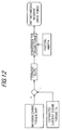
- the desired instantaneous reserve drive force is subtracted from the instantaneous reserve drive force, the difference is multiplied by a coefficient k , and the result is input to a predefined conversion table as input u to obtain an output x that is an indicator.
- the output x obtained is, as indicated, input to a predefined conversion table to obtain an output y that is a ratio coefficient.
- Driving force control is thus conducted with the instantaneous reserve drive force, an index of response to accelerator pedal position change, as the target value, and the desired value is set to a lower value than the instantaneous reserve drive force during normal times so as to suppress occurrence of abrupt driving force change on icy and bad roads and thereby prevent spin and the like.
- the program goes to S214, in which it is checked whether the absolute value of the slope-specific resistance ( msin ⁇ ) is smaller than a prescribed value A.
- S214 it is judged that the vehicle is traveling on a low- ⁇ -road with low traction and the program goes to S204 and ensuing steps to conduct low- ⁇ -road control, and when it is YES, the program goes to S216, in which the road is judged to be normal and control is conducted based on driving force for normal road.
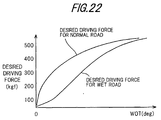
- the desired driving force is decided in accordance with the characteristics shown in Figure 22, the calculated actual driving force is subtracted from the desired driving force, and the ratio is set to the product of the difference and the coefficient k .
- the produced engine torque is calculated from the engine speed Ne and the accelerator pedal position ⁇ acc
- the desired driving force is decided from the calculated torque and the vehicle speed V
- the ratio is controlled to obtain the decided desired driving force.
- the desired value is determined from the driving force curve for wet road in Figure 22 and the ratio is set as in the case of the driving force control for normal road in S216.
- the desired value is set lower than that for driving force control for normal road and the ratio is set based on the set driving force.
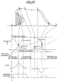
- Figure 24 is a subroutine flow chart for explaining this processing and Figure 25 is a diagram for explaining the processing.
- This processing utilizes the concept of a function fmount( ⁇ n) for mountain/town road discrimination to discriminate whether the region the vehicle is running in is a mountainous region or an urban region and appropriately changes the regulation gains k1 and k2 of the instantaneous reserve drive force and the driving force according to the result. Specifically, it changes the control response (speed of convergence on desired value) according to the driving conditions.
- Figure 26 is the characteristic curve of the function for mountain/town road discrimination.
- the function for mountain/town road discrimination indicates the degree to which the region in which the vehicle is currently running is mountainous or urban. The degree is determined by applying the absolute value of the estimated slope ⁇ to the characteristic curve of Figure 26.
- the characteristic curve of the function for mountain/town road discrimination is therefore established so that the integrated value becomes large when driving on a mountainous road having many sharp slopes and becomes a small value when driving on an urban road having only gradual slopes.
- This function for mountain/town road discrimination is applied to the characteristic curve of Figure 27 to obtain the desired driving force.
- the mountain/town road discrimination function is small, i.e., when the resemblance to a town road is high, the desired drive force is large.
- the desired driving force becomes zero to make the running resistance and the engine braking force the same, thereby preventing speed increase during downhill driving.
- normal engine braking capability is maintained to minimize incompatibility with other vehicles ahead and behind.
- the long-span estimated slope ⁇ long is used to determine the mountain/town road discrimination function.
- the program then goes to S304, in which it is checked whether the determined mountain/town road discrimination function is smaller than the prescribed value A and larger than the prescribed value B.
- the prescribed values A and B are an overflow limiter and an underflow limiter, respectively.
- the program goes to S306, in which the mountain/town road discrimination function is held.
- the program goes to S308, in which the limit value A or B is held as the mountain/town road discrimination function fmount( ⁇ n).
- the prescribed value C is a mountain road discrimination threshold whose value is set to the time-course attenuated value of the cornering resistance Rc peak-hold value.
- Figure 28 is the characteristic curve of the mountain road discrimination threshold value.
- the mountain road discrimination threshold value C is determined using the time-course attenuated peak-hold value of the cornering resistance Rc. As shown, the mountain road discrimination threshold value is made inversely proportional to the cornering resistance hold-down value. By this, even in the case of a road with relatively gradual slopes, the threshold stays at a small value if many sharp curves are encountered, i.e., when the calculated value of the cornering resistance is high. This makes it easier to discriminate mountain roads.
- step S312 the program goes to step S312, in which the vehicle is discriminated to be running on a mountain road, and then to S314, in which it is checked whether downhill ratio control is in effect.
- the program goes to S324, in which the desired driving force is set to a specified value (e.g., 5kgf).
- a specified value e.g., 5kgf.
- the regulation gains k1 and k2 are set to predefined town road specified values.
- the program skips S324 and goes to S326.
- the mountain road specified values of the gains k1 and k2 are set higher than their town road specified values so that the ratio control is effected with higher response during mountain road driving than during town road driving.
- the system according to this embodiment enhances drivability by effecting speed ratio control that closely reflects the intention of the operator. Moreover, the system can estimate the road slope accurately, without estimation lag, and control the gear ratio (speed ratio) optimally, thereby enhancing drivability.
- the embodiment is configured to have a system for controlling an automatic transmission (24) of a vehicle (29) having an input shaft (28) connected to an internal combustion engine (10) mounted on the vehicle and an output shaft (30) connected to driven wheels of the vehicle, the transmission transmitting output torque generated by the engine and inputted through the input shaft to the driven wheels through the output shaft.
- the characteristic features of the system is that it includes operating condition detecting means (coolant temperature sensor 106, throttle position sensor 108, accelerator position sensor 110, brake switch 112, vehicle speed sensor 122, etc.) for detecting operating conditions of the engine and the vehicle including at least a vehicle speed (v) and a throttle opening ( ⁇ th); running resistance calculating means (integrated control unit 300, S108) for calculating a running resistance (R) acting on the vehicle; driving force calculating means (integrated control unit 300, S14, S104) for calculating a driving force (F) generated by the vehicle; slope estimating means (integrated control unit 300, S10, S106, S110, S114 - S124, S134, S136, S142) for estimating a slope ( ⁇ ) of a road on which the vehicle travels based on at least the calculated running resistance and the driving force; running state discriminating means (integrated control unit 300, S22) for comparing the estimated slope with a predetermined value ( ⁇ , ⁇ ) and for discriminating a running state of the vehicle
- the gear ratio determining means corrects the calculated driving force difference based on at least one of the estimated slope and the detected vehicle speed (V, as illustrated in the characteristics of the desired instantaneous reserve drive force in Figure 14 and the inclined characteristic of the desired instantaneous reserve drive force in Figure 15). With this, the drivability is enhanced by enabling control even better matched to the slope of the road.
- the gear ratio determining means corrects the calculated driving force difference based on at least the throttle opening ( ⁇ th) and a change in the throttle opening (dth, as illustrated in S14 - S18 and the characteristics of the desired instantaneous reserve drive force in Figure 14). With this, the drivability is enhanced by enabling control matched to both the slope of the road and the desire of the operator.
- the gear ratio determining means determines the gear ratio based on the calculated driving force difference and the running resistance when it is discriminated that the vehicle is hill- descending (as shown in S24 - S40 and Figure 16 block diagram). With this, the drivability is enhanced by enabling control matched to the slope, particularly downhill slope, of the road.
- the gear ratio determining means determines the gear ratio such that the calculated driving force difference becomes equal to the calculated running resistance, when it is discriminated that the vehicle is hill-descending, as shown in S28, S316). With this, the drivability is enhanced by enabling control matched to the desire of the operator during downhill driving.
- the gear ratio determining means determines the gear ratio such that a difference between the calculated driving force difference and the calculated running resistance becomes a predetermined value, when it is discriminated that the vehicle is hill-descending, as shown in S28, S324) With this, the drivability is enhanced by enabling control matched to the desire of the operator during downhill driving.
- the slope estimating means includes; vehicle acceleration detecting means (integrated control unit 300, S134) for detecting the vehicle acceleration (dv) of the vehicle; data processing time constant changing means (integrated control unit 300, S100, S136) for changing a time constant of data processing necessary for the estimation of the slope in response to the detected vehicle acceleration.
- vehicle acceleration detecting means integrated control unit 300, S134
- data processing time constant changing means integrated control unit 300, S100, S136
- the slope estimating means includes; braking force estimating means (integrated control unit 300, S114 - S124) for estimating a braking force based on the estimated slope before braking and the estimated slope during braking when a brake is operated; and holds the estimated slope based on the estimated braking force.
- the slope estimating means includes; cornering resistance estimating means (integrated control unit 300, S106, S142) for estimating a cornering resistance based on a turning force of the vehicle; and corrects the estimated slope based on the estimated cornering resistance.
- cornering resistance estimating means integrated control unit 300, S106, S142 for estimating a cornering resistance based on a turning force of the vehicle.
- the embodiment is configured to have a system for controlling an automatic transmission (24) of a vehicle (29) having an input shaft (28) connected to an internal combustion engine (10) mounted on the vehicle and an output shaft (30) connected to driven wheels of the vehicle, the transmission transmitting output torque generated by the engine and inputted through the input shaft to the driven wheels through the output shaft.
- the characteristic features of the system is that it includes operating condition detecting means (coolant temperature sensor 106, throttle position sensor 108, accelerator position sensor 110, brake switch 112, vehicle speed sensor 122, etc.) for detecting operating conditions of the engine and the vehicle including at least a vehicle speed (v) and a throttle opening ( ⁇ th); actual driving force calculating means (integrated control unit 300, S14, Figure 7) for calculating an actual driving force generated by the vehicle based on at least the detected throttle opening; operator desire estimating means (integrated control unit 300, S14 - S18, Figure 7) for estimating a value desired by a vehicle operator based on at least the detected throttle opening (more specifically, operator desire estimating means for inputting the detected throttle opening to a first predetermined mode describing the operating condition of the vehicle and for calculating the operator desire estimated value in throttle opening and throttle opening change); indicator conversion means (integrated control unit 300, S14 - S18, Figure 4) for convening the actual driving force and the operator desire estimated value to an evaluation indictor (more specifically, subject vehicle
- the driving force controlling means includes: slope estimating means (integrated control unit 300, S10, S24, S28) for estimating a slope of a road on which the vehicle travels; and desired driving force determining means (integrated control unit 300, S200 - S218) for determining a desired driving force based on the estimated slope; and wherein the driving force controlling means feedback-controls such that the driving force converges the desired driving force.
- a control system for an automatic vehicle transmission in which the running resistance acting on the vehicle and the driving force generated by the vehicle are calculated, and a slope of a road on which the vehicle travels is estimated based on at least the calculated running resistance and the driving force.
- the vehicle running state is then discriminated by comparing the estimated slope with a predetermined value.
- the maximum driving force to be generated by the vehicle at the current gear ratio is calculated to determine a driving force difference from the calculated driving force and the gear ratio of the transmission is determined such that the driving force difference is a predetermined value in response to the discriminated running state, thereby enhancing the drivability.
Landscapes
- Engineering & Computer Science (AREA)
- General Engineering & Computer Science (AREA)
- Mechanical Engineering (AREA)
- Chemical & Material Sciences (AREA)
- Combustion & Propulsion (AREA)
- Transportation (AREA)
- Control Of Transmission Device (AREA)
Applications Claiming Priority (4)
| Application Number | Priority Date | Filing Date | Title |
|---|---|---|---|
| JP10219857A JP2000033826A (ja) | 1998-07-17 | 1998-07-17 | 車両用自動変速機などの制御装置 |
| JP10219858A JP2000035117A (ja) | 1998-07-17 | 1998-07-17 | 車両用自動変速機の制御装置 |
| JP21985798 | 1998-07-17 | ||
| JP21985898 | 1998-07-17 |
Publications (3)
| Publication Number | Publication Date |
|---|---|
| EP0972971A2 true EP0972971A2 (de) | 2000-01-19 |
| EP0972971A3 EP0972971A3 (de) | 2000-10-18 |
| EP0972971B1 EP0972971B1 (de) | 2006-03-08 |
Family
ID=26523379
Family Applications (1)
| Application Number | Title | Priority Date | Filing Date |
|---|---|---|---|
| EP99114029A Expired - Lifetime EP0972971B1 (de) | 1998-07-17 | 1999-07-19 | Steuerung für Kraftfahrzeug-Automatikgetriebe, insbesondere mit Bestimmung des Fahrwiderstandes |
Country Status (3)
| Country | Link |
|---|---|
| US (1) | US6427108B1 (de) |
| EP (1) | EP0972971B1 (de) |
| DE (1) | DE69930180T2 (de) |
Cited By (9)
| Publication number | Priority date | Publication date | Assignee | Title |
|---|---|---|---|---|
| WO2003106212A1 (en) * | 2002-06-17 | 2003-12-24 | Volvo Lastvagnar Ab | Drive means for motor vehicles |
| FR2847639A1 (fr) * | 2002-11-21 | 2004-05-28 | Renault Sa | Procede de commande d'une transmission automatique d'un vehicule en situation de descente |
| FR2875203A1 (fr) * | 2004-09-10 | 2006-03-17 | Renault Sas | Procede d'elaboration d'une consigne pour l'amelioration de l'agrement de conduite pour un dispositif de transmission d'un groupe motopropulseur de vehicule automobile et dispositif correspondant |
| EP1229311A3 (de) * | 2001-02-01 | 2006-12-13 | Miyama, Inc. | Vorrichtung und Verfahren zur Analyse des Zustands eines Fahrzeuges |
| EP2436954A3 (de) * | 2010-09-30 | 2012-12-05 | JATCO Ltd | Stufenloses Getriebe und zugehöriges Steuerverfahren |
| CN103727226A (zh) * | 2014-01-23 | 2014-04-16 | 安徽江淮汽车股份有限公司 | 双离合器自动变速箱大脚模式起步控制方法 |
| WO2018108660A1 (en) * | 2016-12-16 | 2018-06-21 | Robert Bosch Gmbh | A controller and method to provide torque assistance to a vehicle |
| CN114860603A (zh) * | 2022-05-20 | 2022-08-05 | 浙江极氪智能科技有限公司 | 自适应巡航功能测试方法、电子设备及存储介质 |
| EP4056433A1 (de) * | 2021-03-11 | 2022-09-14 | Nio Technology (Anhui) Co., Ltd | Gefällebremsdruck-bestimmungsverfahren und -system, und fahrzeug |
Families Citing this family (32)
| Publication number | Priority date | Publication date | Assignee | Title |
|---|---|---|---|---|
| US6634982B2 (en) * | 1999-12-24 | 2003-10-21 | Aisin Aw Co., Ltd. | Automatic speed changer controller, automatic speed changer control method, and recording medium having program for method recorded thereon |
| JP2002161976A (ja) * | 2000-09-18 | 2002-06-07 | Fuji Heavy Ind Ltd | 作業用車両 |
| JP3925062B2 (ja) * | 2000-09-19 | 2007-06-06 | 三菱電機株式会社 | 車載電子制御装置 |
| US6568257B2 (en) * | 2001-10-18 | 2003-05-27 | Ford Global Technologies, Llc | Cylinder air charge estimate |
| DE10222665A1 (de) * | 2002-05-22 | 2003-12-11 | Bosch Gmbh Robert | Verfahren zur Konfiguration einer Getriebesteuerung für Kraftfahrzeuge |
| US6863047B2 (en) * | 2002-07-22 | 2005-03-08 | Siemens Vdo Automotive Corporation | Method of controlling engine speed during performance shift |
| US6827666B2 (en) * | 2002-09-04 | 2004-12-07 | Daimlerchrysler Corporation | Transmission gear ratio selection |
| DE10333962A1 (de) * | 2003-07-25 | 2005-02-10 | Robert Bosch Gmbh | Verfahren zum Betreiben eines Fahrzeugs |
| JP2005193811A (ja) * | 2004-01-08 | 2005-07-21 | Toyota Motor Corp | 車両の統合制御システム |
| EP1593566A1 (de) * | 2004-05-03 | 2005-11-09 | Delphi Technologies, Inc. | Funktion zur Anfahrunterstützung eines an einer Steigung stehenden Fahrzeuges |
| JP4541839B2 (ja) * | 2004-11-05 | 2010-09-08 | 三菱電機株式会社 | 路面の傾斜判定システム |
| JP4587121B2 (ja) * | 2005-05-31 | 2010-11-24 | 株式会社デンソー | 補機付きのエンジンの制御装置 |
| US7347184B2 (en) * | 2005-11-01 | 2008-03-25 | Denso Corporation | Controller and controlling method for internal combustion engine |
| JP4265633B2 (ja) * | 2006-09-15 | 2009-05-20 | トヨタ自動車株式会社 | 電動パーキングブレーキシステム |
| US8041492B2 (en) * | 2006-10-31 | 2011-10-18 | Clark Equipment Company | Engine load management for power machines |
| SE532715C2 (sv) * | 2008-06-18 | 2010-03-23 | Scania Cv Abp | Förfarande och system för transmissionsstyrning vid lågt effektbehov |
| SE534455C2 (sv) * | 2009-12-17 | 2011-08-30 | Scania Cv Ab | Förfarande och system för framförande av ett fordon |
| SE535204C2 (sv) | 2009-12-17 | 2012-05-22 | Scania Cv Ab | Metod för bestämning av drivkraftkapacitet hos ett motorfordon |
| SE534647C2 (sv) * | 2009-12-17 | 2011-11-08 | Scania Cv Ab | Farthållare för ett motorfordon och en metod för styrning av en sådan |
| DE102010006643A1 (de) * | 2010-02-03 | 2011-08-04 | GM Global Technology Operations LLC, ( n. d. Ges. d. Staates Delaware ), Mich. | Verfahren zur Steuerung eines Automatikgetriebes eines Kraftfahrzeugs, Steuervorrichtung für ein Automatikgetriebe eines Kraftfahrzeugs und Kraftfahrzeug |
| US8543303B2 (en) * | 2011-02-01 | 2013-09-24 | Rollfree Tek, Llc | Anti-rollback control system for hybrid and conventional powertrain vehicles |
| US20110166756A1 (en) * | 2011-02-01 | 2011-07-07 | Essam Tawfik Marcus | Anti-rollback Control System for Hybrid and Conventional Powertrain Vehicles |
| US20110172868A1 (en) * | 2011-02-01 | 2011-07-14 | Essam Tawfik Marcus | Anti-rollback Control System for Motor Vehicles |
| US20110178666A1 (en) * | 2011-02-01 | 2011-07-21 | Essam Tawfik Marcus | Anti-rollback Control System for Motor Vehicles |
| WO2014027065A1 (en) * | 2012-08-16 | 2014-02-20 | Jaguar Land Rover Limited | System and method for selecting a driveline gear ratio |
| KR101427947B1 (ko) * | 2012-12-12 | 2014-08-08 | 현대자동차 주식회사 | 차량 주행 제어 시스템 |
| JP6092791B2 (ja) * | 2014-01-15 | 2017-03-08 | 富士重工業株式会社 | 無段変速機の変速制御装置 |
| JP2017115590A (ja) * | 2015-12-21 | 2017-06-29 | 株式会社デンソー | 電子制御装置 |
| CN106443187A (zh) * | 2016-09-23 | 2017-02-22 | 江西洪都航空工业集团有限责任公司 | 一种温度选择器检测方法 |
| EP3575133B1 (de) * | 2017-01-24 | 2022-03-09 | Nissan Motor Co., Ltd. | Elektrofahrzeugsteuerungsverfahren und -steuerungsvorrichtung |
| KR20210152209A (ko) * | 2020-06-08 | 2021-12-15 | 현대자동차주식회사 | 하이브리드 차량의 제어 장치 및 방법 |
| JP7593245B2 (ja) * | 2021-06-21 | 2024-12-03 | 株式会社デンソー | 走行制御装置、走行制御方法、および走行制御プログラム |
Citations (2)
| Publication number | Priority date | Publication date | Assignee | Title |
|---|---|---|---|---|
| JPH04231218A (ja) | 1990-12-27 | 1992-08-20 | Toyota Motor Corp | 駆動力制御装置 |
| JPH06201523A (ja) | 1993-01-08 | 1994-07-19 | Hitachi Ltd | 自動車の出力軸トルク推定装置及び車重算出装置 |
Family Cites Families (18)
| Publication number | Priority date | Publication date | Assignee | Title |
|---|---|---|---|---|
| US3747438A (en) * | 1972-03-28 | 1973-07-24 | Toyota Motor Co Ltd | Shift control system for automatic transmission |
| US4625590A (en) | 1980-05-10 | 1986-12-02 | Robert Bosch Gmbh | Control apparatus for an automatic transmission |
| DE3237508A1 (de) * | 1982-10-09 | 1984-04-19 | Wabco Westinghouse Fahrzeugbremsen GmbH, 3000 Hannover | Gangschaltung fuer ein fremdkraftbetaetigtes getriebe |
| DE3334718A1 (de) | 1983-09-26 | 1985-04-04 | Wabco Westinghouse Fahrzeugbremsen GmbH, 3000 Hannover | Getriebesteuerung fuer ein strassenfahrzeug |
| US4819163A (en) * | 1985-12-21 | 1989-04-04 | Toyota Jidosha Kabushiki Kaisha | Driving power control system |
| US5231582A (en) | 1989-03-29 | 1993-07-27 | Nissan Motor Company | Shifting control system for automotive automatic power transmission with enhanced variable shift pattern selection depending upon a resistance based upon vehicle acceleration and an engine parameter |
| JP3318945B2 (ja) * | 1992-03-02 | 2002-08-26 | 株式会社日立製作所 | 自動車用制御装置、自動車制御システム及び自動車の制御方法 |
| DE4328893B4 (de) * | 1992-08-27 | 2007-07-05 | Hitachi, Ltd. | Verfahren und Einrichtung zur Steuerung eines Automatikgetriebes eines Fahrzeugs in Abhängigkeit von einem Gefälle einer Fahrbahn |
| JPH0694116A (ja) | 1992-09-08 | 1994-04-05 | Hitachi Ltd | 自動変速制御装置 |
| US5618243A (en) * | 1993-07-20 | 1997-04-08 | Mitsubisi Jidosha Kogyo Kabushiki Kaisha | Speed change control method for an automotive automatic transmission |
| JP3301183B2 (ja) * | 1993-11-24 | 2002-07-15 | 日産自動車株式会社 | 車両の前後輪間駆動力配分制御装置 |
| JP3461572B2 (ja) * | 1994-06-09 | 2003-10-27 | 株式会社日立ユニシアオートモティブ | 車両の制御装置 |
| JP3203976B2 (ja) * | 1994-09-05 | 2001-09-04 | 日産自動車株式会社 | 車両用駆動力制御装置 |
| JP3652403B2 (ja) * | 1995-05-01 | 2005-05-25 | 本田技研工業株式会社 | 前後輪駆動車両 |
| JPH094705A (ja) | 1995-06-16 | 1997-01-07 | Aisin Aw Co Ltd | 自動変速機の制御装置 |
| KR970066191A (ko) * | 1996-03-01 | 1997-10-13 | 가나이 쯔도무 | 자동 변속기의 제어 장치 및 제어 방법 |
| US5895435A (en) * | 1996-03-01 | 1999-04-20 | Toyota Jidosha Kabushiki Kaisha | Vehicle drive mode estimating device, and vehicle control apparatus, transmission shift control apparatus and vehicle drive force control apparatus including drive mode estimating device |
| JP3277837B2 (ja) * | 1996-03-15 | 2002-04-22 | トヨタ自動車株式会社 | 変速機の制御装置 |
-
1999
- 1999-07-16 US US09/354,337 patent/US6427108B1/en not_active Expired - Fee Related
- 1999-07-19 DE DE69930180T patent/DE69930180T2/de not_active Expired - Fee Related
- 1999-07-19 EP EP99114029A patent/EP0972971B1/de not_active Expired - Lifetime
Patent Citations (2)
| Publication number | Priority date | Publication date | Assignee | Title |
|---|---|---|---|---|
| JPH04231218A (ja) | 1990-12-27 | 1992-08-20 | Toyota Motor Corp | 駆動力制御装置 |
| JPH06201523A (ja) | 1993-01-08 | 1994-07-19 | Hitachi Ltd | 自動車の出力軸トルク推定装置及び車重算出装置 |
Cited By (14)
| Publication number | Priority date | Publication date | Assignee | Title |
|---|---|---|---|---|
| EP1229311A3 (de) * | 2001-02-01 | 2006-12-13 | Miyama, Inc. | Vorrichtung und Verfahren zur Analyse des Zustands eines Fahrzeuges |
| WO2003106212A1 (en) * | 2002-06-17 | 2003-12-24 | Volvo Lastvagnar Ab | Drive means for motor vehicles |
| FR2847639A1 (fr) * | 2002-11-21 | 2004-05-28 | Renault Sa | Procede de commande d'une transmission automatique d'un vehicule en situation de descente |
| WO2004048818A1 (fr) * | 2002-11-21 | 2004-06-10 | Renault S.A.S | Procede de commande d’une transmission automatique d’un vehicule en situation de descente |
| US7987034B2 (en) | 2002-11-21 | 2011-07-26 | Renault S.A.S. | Method for controlling automatic transmission of a vehicle on a downhill slope |
| FR2875203A1 (fr) * | 2004-09-10 | 2006-03-17 | Renault Sas | Procede d'elaboration d'une consigne pour l'amelioration de l'agrement de conduite pour un dispositif de transmission d'un groupe motopropulseur de vehicule automobile et dispositif correspondant |
| EP2436954A3 (de) * | 2010-09-30 | 2012-12-05 | JATCO Ltd | Stufenloses Getriebe und zugehöriges Steuerverfahren |
| US8560189B2 (en) | 2010-09-30 | 2013-10-15 | Jatco Ltd | Continuously variable transmission and shift control method |
| CN103727226A (zh) * | 2014-01-23 | 2014-04-16 | 安徽江淮汽车股份有限公司 | 双离合器自动变速箱大脚模式起步控制方法 |
| CN103727226B (zh) * | 2014-01-23 | 2016-03-16 | 安徽江淮汽车股份有限公司 | 双离合器自动变速箱大脚模式起步控制方法 |
| WO2018108660A1 (en) * | 2016-12-16 | 2018-06-21 | Robert Bosch Gmbh | A controller and method to provide torque assistance to a vehicle |
| EP4056433A1 (de) * | 2021-03-11 | 2022-09-14 | Nio Technology (Anhui) Co., Ltd | Gefällebremsdruck-bestimmungsverfahren und -system, und fahrzeug |
| US12377826B2 (en) * | 2021-03-11 | 2025-08-05 | Nio Technology (Anhui) Co., Ltd | Slope brake pressure determining method and determining system, and vehicle |
| CN114860603A (zh) * | 2022-05-20 | 2022-08-05 | 浙江极氪智能科技有限公司 | 自适应巡航功能测试方法、电子设备及存储介质 |
Also Published As
| Publication number | Publication date |
|---|---|
| US6427108B1 (en) | 2002-07-30 |
| DE69930180D1 (de) | 2006-05-04 |
| EP0972971A3 (de) | 2000-10-18 |
| EP0972971B1 (de) | 2006-03-08 |
| DE69930180T2 (de) | 2006-07-27 |
Similar Documents
| Publication | Publication Date | Title |
|---|---|---|
| EP0972971B1 (de) | Steuerung für Kraftfahrzeug-Automatikgetriebe, insbesondere mit Bestimmung des Fahrwiderstandes | |
| US6216068B1 (en) | Method for driver-behavior-adaptive control of a variably adjustable motor vehicle accessory | |
| US5711712A (en) | Controller for an automatic motor vehicle transmission | |
| US7899587B2 (en) | Front and rear wheel drive vehicle | |
| US20120179342A1 (en) | Control device for vehicle | |
| US20050125137A1 (en) | Deceleration control apparatus and method for a vehicle | |
| US5603673A (en) | Change gear control device using acceleration and gear ratio as parameters for automatic transmission in a motor vehicle and the method therefor | |
| KR960004283B1 (ko) | 자동차의 자동변속기용의 변속기어 제어장치와 그 방법 | |
| EP1052132B1 (de) | Fahrgeschwindigkeitsregelsystem | |
| JP2001513181A (ja) | トランスミッションの変速比調整系 | |
| JPH11294547A (ja) | 車両用自動変速の制御装置および制御方法 | |
| US5514051A (en) | Method and an arrangement for controlling an automatic transmission | |
| KR100374430B1 (ko) | 트랙션슬립제어기 | |
| JP3536523B2 (ja) | 車両用駆動力制御装置 | |
| JPH07239021A (ja) | 自動変速機の制御装置 | |
| JP2000035117A (ja) | 車両用自動変速機の制御装置 | |
| KR100898882B1 (ko) | 자동차 제어 장치 | |
| JP3536284B2 (ja) | 前後輪駆動車両 | |
| JP3853447B2 (ja) | トルクコンバータ付き自動変速機を備えた車両のクリープ制御装置 | |
| JP2000035118A (ja) | 車両用自動変速機の制御装置 | |
| JP2000033826A (ja) | 車両用自動変速機などの制御装置 | |
| JP3401354B2 (ja) | 変速機付き車両の制御装置 | |
| JP3463566B2 (ja) | 車両駆動力制御装置 | |
| US7003387B2 (en) | Method for controlling an automatic gearbox according to a road profile | |
| JP3787244B2 (ja) | 車両の速度制御装置 |
Legal Events
| Date | Code | Title | Description |
|---|---|---|---|
| PUAI | Public reference made under article 153(3) epc to a published international application that has entered the european phase |
Free format text: ORIGINAL CODE: 0009012 |
|
| 17P | Request for examination filed |
Effective date: 19990719 |
|
| AK | Designated contracting states |
Kind code of ref document: A2 Designated state(s): DE GB |
|
| AX | Request for extension of the european patent |
Free format text: AL;LT;LV;MK;RO;SI |
|
| RIC1 | Information provided on ipc code assigned before grant |
Free format text: 7F 16H 61/02 A, 7B 60K 28/16 B, 7F 16H 59/14 - |
|
| PUAL | Search report despatched |
Free format text: ORIGINAL CODE: 0009013 |
|
| AK | Designated contracting states |
Kind code of ref document: A3 Designated state(s): AT BE CH CY DE DK ES FI FR GB GR IE IT LI LU MC NL PT SE |
|
| AX | Request for extension of the european patent |
Free format text: AL;LT;LV;MK;RO;SI |
|
| AKX | Designation fees paid |
Free format text: DE GB |
|
| 17Q | First examination report despatched |
Effective date: 20020522 |
|
| GRAP | Despatch of communication of intention to grant a patent |
Free format text: ORIGINAL CODE: EPIDOSNIGR1 |
|
| GRAS | Grant fee paid |
Free format text: ORIGINAL CODE: EPIDOSNIGR3 |
|
| GRAA | (expected) grant |
Free format text: ORIGINAL CODE: 0009210 |
|
| AK | Designated contracting states |
Kind code of ref document: B1 Designated state(s): DE GB |
|
| REG | Reference to a national code |
Ref country code: GB Ref legal event code: FG4D |
|
| REF | Corresponds to: |
Ref document number: 69930180 Country of ref document: DE Date of ref document: 20060504 Kind code of ref document: P |
|
| PGFP | Annual fee paid to national office [announced via postgrant information from national office to epo] |
Ref country code: GB Payment date: 20060719 Year of fee payment: 8 |
|
| PLBE | No opposition filed within time limit |
Free format text: ORIGINAL CODE: 0009261 |
|
| STAA | Information on the status of an ep patent application or granted ep patent |
Free format text: STATUS: NO OPPOSITION FILED WITHIN TIME LIMIT |
|
| 26N | No opposition filed |
Effective date: 20061211 |
|
| PGFP | Annual fee paid to national office [announced via postgrant information from national office to epo] |
Ref country code: DE Payment date: 20070712 Year of fee payment: 9 |
|
| GBPC | Gb: european patent ceased through non-payment of renewal fee |
Effective date: 20070719 |
|
| PG25 | Lapsed in a contracting state [announced via postgrant information from national office to epo] |
Ref country code: GB Free format text: LAPSE BECAUSE OF NON-PAYMENT OF DUE FEES Effective date: 20070719 |
|
| PG25 | Lapsed in a contracting state [announced via postgrant information from national office to epo] |
Ref country code: DE Free format text: LAPSE BECAUSE OF NON-PAYMENT OF DUE FEES Effective date: 20090203 |