EP0972994A1 - Appareil de chauffage pour eau chaude sanitaire - Google Patents
Appareil de chauffage pour eau chaude sanitaire Download PDFInfo
- Publication number
- EP0972994A1 EP0972994A1 EP99202300A EP99202300A EP0972994A1 EP 0972994 A1 EP0972994 A1 EP 0972994A1 EP 99202300 A EP99202300 A EP 99202300A EP 99202300 A EP99202300 A EP 99202300A EP 0972994 A1 EP0972994 A1 EP 0972994A1
- Authority
- EP
- European Patent Office
- Prior art keywords
- sanitary water
- sanitary
- container
- heating
- water
- Prior art date
- Legal status (The legal status is an assumption and is not a legal conclusion. Google has not performed a legal analysis and makes no representation as to the accuracy of the status listed.)
- Granted
Links
- XLYOFNOQVPJJNP-UHFFFAOYSA-N water Substances O XLYOFNOQVPJJNP-UHFFFAOYSA-N 0.000 title claims abstract description 97
- 238000010438 heat treatment Methods 0.000 title claims abstract description 8
- 239000008236 heating water Substances 0.000 claims abstract description 58
- 125000006850 spacer group Chemical group 0.000 claims description 8
- 238000005192 partition Methods 0.000 description 15
- RYGMFSIKBFXOCR-UHFFFAOYSA-N Copper Chemical compound [Cu] RYGMFSIKBFXOCR-UHFFFAOYSA-N 0.000 description 2
- 229910000831 Steel Inorganic materials 0.000 description 2
- 229910052802 copper Inorganic materials 0.000 description 2
- 239000010949 copper Substances 0.000 description 2
- 238000009428 plumbing Methods 0.000 description 2
- 238000010079 rubber tapping Methods 0.000 description 2
- 229910001220 stainless steel Inorganic materials 0.000 description 2
- 239000010935 stainless steel Substances 0.000 description 2
- 239000010959 steel Substances 0.000 description 2
- 238000010276 construction Methods 0.000 description 1
- 238000001816 cooling Methods 0.000 description 1
- 230000003247 decreasing effect Effects 0.000 description 1
- 230000010354 integration Effects 0.000 description 1
- 239000002184 metal Substances 0.000 description 1
- 229910052751 metal Inorganic materials 0.000 description 1
- 238000000034 method Methods 0.000 description 1
- 238000010792 warming Methods 0.000 description 1
- 239000002699 waste material Substances 0.000 description 1
- 238000004804 winding Methods 0.000 description 1
Images


Classifications
-
- F—MECHANICAL ENGINEERING; LIGHTING; HEATING; WEAPONS; BLASTING
- F28—HEAT EXCHANGE IN GENERAL
- F28D—HEAT-EXCHANGE APPARATUS, NOT PROVIDED FOR IN ANOTHER SUBCLASS, IN WHICH THE HEAT-EXCHANGE MEDIA DO NOT COME INTO DIRECT CONTACT
- F28D7/00—Heat-exchange apparatus having stationary tubular conduit assemblies for both heat-exchange media, the media being in contact with different sides of a conduit wall
- F28D7/02—Heat-exchange apparatus having stationary tubular conduit assemblies for both heat-exchange media, the media being in contact with different sides of a conduit wall the conduits being helically coiled
- F28D7/024—Heat-exchange apparatus having stationary tubular conduit assemblies for both heat-exchange media, the media being in contact with different sides of a conduit wall the conduits being helically coiled the conduits of only one medium being helically coiled tubes, the coils having a cylindrical configuration
-
- F—MECHANICAL ENGINEERING; LIGHTING; HEATING; WEAPONS; BLASTING
- F24—HEATING; RANGES; VENTILATING
- F24D—DOMESTIC- OR SPACE-HEATING SYSTEMS, e.g. CENTRAL HEATING SYSTEMS; DOMESTIC HOT-WATER SUPPLY SYSTEMS; ELEMENTS OR COMPONENTS THEREFOR
- F24D3/00—Hot-water central heating systems
- F24D3/08—Hot-water central heating systems in combination with systems for domestic hot-water supply
- F24D3/082—Hot water storage tanks specially adapted therefor
Definitions
- the invention relates to a device for heating Sanitary water with a container for sanitary water in order around which there is a space delimited by walls, in which a tortuous plumbing pipe with some Coils are added that are connected to the container is.
- Such a device also referred to below as a "dispenser” is known from DE-A-19526862.
- the dispenser according to the prior art comprises a relatively large container for sanitary water with a Side wall, around which an annular heating water room is appropriate.
- the helical line extends between the side walls of the heating water room, causing heating water (in countercurrent) helically through the heating water room flows parallel to the sanitary water pipe.
- a disadvantage of the known dispenser is the fact that the heat transfer between the heating water and the sanitary water is not optimal because the heating water only in contact with part of the sanitary water pipe stands.
- Another disadvantage of the known dispenser is in that it is very cold from an initial state takes a long time (namely until the sanitary water in the container was replaced) until heated sanitary water was supplied can be.
- the invention intends to create a dispenser, both a cold and a warm one Initial state quickly the desired amount of sanitary water can deliver at the desired stable temperature.
- Another goal is to create a dispenser, at which the temperature of the heated sanitary water supplied is relatively insensitive to fluctuations in the flow rate of the sanitary water.
- Another object of the invention is to reduce or Prevent limescale from settling on the water parts of the dispenser in contact.
- Yet another object of the invention is to create it a dispenser that is compact and cheap, and that with only a small pressure drop for the heating water and the sanitary water works.
- the device of the type mentioned according to the invention characterized in that the Sanitary water pipe at a certain distance from the Walls of the heating water room.
- the heating water can so the plumbing water pipe, whose turns preferably, but not necessarily, in a certain distance from each other, rinse completely, so that an optimal heat transfer of the heating water to the sanitary water can take place. That can go on Heating water in this way both in parallel and flow across the turns of the sanitary water pipe, what benefits heat transfer and for a low one Pressure drop in the heating water in the dispenser provides.
- the supply temperature of the heating water for example from a A burner's heat exchanger comes down. This avoids local hot zones in the sanitary water, what reduces limescale deposits in the dispenser or avoids.
- the temperature of the sanitary water in the dispenser is smaller. It also improves the tap efficiency.
- a lower heating water discharge temperature increases the energy from the heating water at its Warming can be absorbed.
- Sanitary water discharge temperature thanks to the low supply temperature the heating water less sensitive to fluctuations in the flow rate of the sanitary water.
- a temperature sensor in the drained sanitary water which is usually for temperature control of the discharged sanitary water is dispensed with and submit for the purpose of such a regulation Temperature sensor off, which is usually already in the Heating water supply is available.
- spacers The distance between the sanitary water pipe and the Walls of the boiler room, including the wall of the Container, is ensured by spacers.
- the Spacers formed by locally removing the walls of the Boiler room deformed, separate spacers can but also remedy, preferably in the form of elongated elements as if attached to the walls Ribs that run across the turns of the Sanitary water pipe extend.
- the Sanitary water pipe at least two helical winding line parts, which are coaxial to each other are arranged. This distribution of Sanitary water pipe in pipe parts provides one significant enlargement of the heat-exchanging surface.
- the individual line parts are preferably in interconnected annular spaces arranged, with an annular wall between the line parts is appropriate.
- the heating water in the ring-shaped Can be crossed in countercurrent to the sanitary water flow the line parts, so that a very good Heat transfer and a very large heating capacity is achieved. This allows the length of the Sanitary water pipes are limited, which only one low pressure loss of the sanitary water over the Conveyor vessel has the consequence, and that too Heating water must travel a limited way, so that the pressure drop in the heating water over the Dispenser is small.
- Integrating a container with sanitary water into the Dispenser leads to a warm initial condition fast delivery of hot sanitary water because it is in the Container is kept in stock, especially if a Sanitary water inlet opens and enters the tank Sanitary water outlet with the end facing away from the container the sanitary water pipe is coupled.
- the limescale in the dispenser is also in accordance with the Invention by its relatively low Operating temperature reduced, first because immediately after Sanitary water was tapped and the tapping was stopped, cold water in the tank the average temperature decreased. Second is thanks to the in the heating water room located container a relatively small amount Heating water available in the dispenser, which is additional can contribute to the fact that the average temperature in Dispenser is lowered. Third, the temperature of the Heating water in the dispenser during dispensing thanks to the improved heat transfer in the dispenser is lower his.
- the ratio is Amount of sanitary water in the dispenser to the amount of heating water got bigger.
- the integration of one leads Container with sanitary water in the dispenser at one cold initial condition to a quick delivery warm Sanitary water, since there is relatively little heating water in the Dispenser is located, which flows quickly.
- the Sanitary water pipe the container which is a very compact, simple and therefore cheap construction results.
- the container is centrally located in the heating water room, so that following the tap of sanitary water if that Cones finished, direct and very effective
- the sanitary water in the tank is heated.
- the heating water and the sanitary water in heat is removed from the sanitary water pipe cool evenly, causing limescale in the dispenser reduced. Even if several times in quick succession Sanitary water is tapped, it becomes an undesirably high Temperature prevented.
- the Container is annular, and is the Sanitary water pipe surrounded by the tank. Also in this Fall finds direct heating of the sanitary water instead, but inside out (assuming that the sanitary water first through the tank and then flows through the sanitary water pipe and the heating water in cross-counterflow to the sanitary water flows). The warmest heating water is in the central part of the device so that the Cooling losses are relatively low.
- the container can on the top and bottom of the device extend further by means of a double wall.
- Figures 1 and 2 show a dispenser, the one cylindrical jacket 1, for example made of steel an upper wall 1a and a lower wall 1b.
- the shell 1 Within the shell 1 are three concentric annular partitions 2a, 2b and 2c for example made of steel.
- the partitions 2a and 2c are attached to the bottom wall 1b of the jacket 1, a annular gap between the top of each Wall 2a, 2c and the top wall 1a of the jacket 1 open remains.
- the partition 2b is on the Top wall 1a attached, the annular gap between the lower edge of the partition 2b and the Bottom wall 1b of the jacket 1 remains open.
- the Partitions can also be placed in the column continue and there with one or more Perforations are provided.
- the spiral 4 comprises three helical parts: a first Part lies between the partitions 2a and 2b the second part lies between the partitions 2b and 2c and a third part lies between the intermediate wall 2c and the side wall of the jacket 1.
- the centrally located Container 3 and the parts of the spiral 4 are such connected that sanitary water to be heated, that flows into the jacket 1 on one Sanitary water inlet 7 first in the container at the Bottom flows in and from the top of the container 3 out into the top turn of the first part of the Spiral 4 flows. Then the sanitary water flows from the lowest turn of the first part of the spiral 4 to the lowest turn of the second part of the spiral 4 and from the top turn of the second part of the Spiral 4 to the top turn of the third part of the Spiral 4.
- the sanitary water leaves the jacket 1 through one Sanitary water outlet 8.
- the sanitary water and the heating water can also in opposite directions to those previously described flow in the respective directions through the dispenser.
- the jacket 1 and the Partitions 2a, 2b and 2c each with ribs 9 for Example made of plastic or metal.
- Ribs 9 ensure that the turns of the spiral in one certain distance from the jacket 1, the partitions 2a-2c and the container remain for optimal flow of the dispenser through the heating water and a optimal heat transfer between the heating water and to ensure the sanitary water.
- the container 3 can be provided with ribs 9 to the partition 2a to keep at a certain distance.
- the ribs or other spacers can also be formed by the respective wall in a deep-drawing process appropriately deformed.
- FIG. 3 shows a dispensing vessel, which comprises: a jacket 1 with an upper wall 1a and a lower wall 1b, one Partition wall 2d, which on the lower wall 1b of the jacket 1 is attached, with an annular gap between the Partition wall 2d and the top wall 1a is released; a centrally arranged cylindrical container 3, a spiral 4 with two helically wound Line parts that are arranged concentrically and have adjacent turns, one Heating water inlet 5, a heating water outlet 6, a sanitary water inlet 7, which extends to the upper part of the container 3 extends into a sanitary water outlet 8 and ribs 9.
- the sanitary water flows in the dispenser from Sanitary water inlet 7 to the sanitary water outlet 8 while the heating water from the heating water inlet 5 to Heating water outlet 6 flows.
- FIG. 4 shows a dispensing vessel, which comprises: a jacket 1 with an upper wall 1a and a lower wall 1b, one Partition 2e, which on the top wall 1a of the jacket 1 is attached, with an annular gap between the Partition 2e and bottom wall 1b is left free, an annular container 3 located on the side wall of the jacket 1 extends a centrally arranged spiral 4, a heating water inlet 5, a Heating water outlet 6, a sanitary water inlet 7, a sanitary water outlet 8 and a spacer 10.
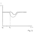
- Figure 5 shows the with a solid line Temperature T of the sanitary water on the Sanitary water outlet 7 of a tap previously shown over time t.
- the time of the start of the tap Sanitary water is designated tO and t1 the time of the start of heat delivery to the Heating water for example through a burner Combination boiler.
- tO and t1 the time of the start of heat delivery to the Heating water for example through a burner Combination boiler.
- tO and t1 the time of the start of heat delivery to the Heating water for example through a burner Combination boiler.
- tO and t1 the time of the start of heat delivery to the Heating water for example through a burner Combination boiler.
- tO and t1 the time of the start of heat delivery to the Heating water for example through a burner Combination boiler.
- tO and t1 the time of the start of heat delivery to the Heating water for example through a burner Combination boiler.
- tO and t1 the time of the start of heat delivery to
- the sanitary water tank have many different shapes, not exclusively cylindrical or ring-shaped, but also for example mushroom-shaped or dumbbell-shaped.
- the container be made up of several parts.
Landscapes
- Engineering & Computer Science (AREA)
- Physics & Mathematics (AREA)
- Thermal Sciences (AREA)
- Mechanical Engineering (AREA)
- General Engineering & Computer Science (AREA)
- Water Supply & Treatment (AREA)
- Chemical & Material Sciences (AREA)
- Combustion & Propulsion (AREA)
- Heat-Pump Type And Storage Water Heaters (AREA)
- Instantaneous Water Boilers, Portable Hot-Water Supply Apparatuses, And Control Of Portable Hot-Water Supply Apparatuses (AREA)
Applications Claiming Priority (2)
| Application Number | Priority Date | Filing Date | Title |
|---|---|---|---|
| NL1009669A NL1009669C2 (nl) | 1998-07-16 | 1998-07-16 | Inrichting voor het verwarmen van sanitairwater. |
| NL1009669 | 1998-07-16 |
Publications (2)
| Publication Number | Publication Date |
|---|---|
| EP0972994A1 true EP0972994A1 (fr) | 2000-01-19 |
| EP0972994B1 EP0972994B1 (fr) | 2005-04-20 |
Family
ID=19767507
Family Applications (1)
| Application Number | Title | Priority Date | Filing Date |
|---|---|---|---|
| EP19990202300 Expired - Lifetime EP0972994B1 (fr) | 1998-07-16 | 1999-07-12 | Appareil de chauffage pour eau chaude sanitaire |
Country Status (2)
| Country | Link |
|---|---|
| EP (1) | EP0972994B1 (fr) |
| NL (1) | NL1009669C2 (fr) |
Cited By (3)
| Publication number | Priority date | Publication date | Assignee | Title |
|---|---|---|---|---|
| WO2001065186A1 (fr) * | 2000-03-03 | 2001-09-07 | Merloni Termosanitari S.P.A. | Nouveau concept, chauffe-eau rapide a capacite de stockage |
| EP1672304A1 (fr) * | 2004-12-18 | 2006-06-21 | Neue Energie-Verwertungsgesellschaft mbH | Echangeur de chaleur |
| EP3358271A1 (fr) * | 2017-02-07 | 2018-08-08 | Aic Spó Ka Akcyjna | Chauffe-eau et tube en serpentin pour un échangeur de chaleur, en particulier un échangeur destiné à ce chauffe-eau spécifique |
Citations (3)
| Publication number | Priority date | Publication date | Assignee | Title |
|---|---|---|---|---|
| US3544005A (en) * | 1968-01-13 | 1970-12-01 | Vaillant Joh Kg | Hot water circulation heating system |
| FR2660056A1 (fr) * | 1990-03-23 | 1991-09-27 | Muller Cie | Echangeur pour eau chaude sanitaire notamment pour chaudiere murale. |
| DE9112876U1 (de) * | 1990-10-19 | 1992-01-09 | Joh. Vaillant Gmbh U. Co, 5630 Remscheid | Brauchwasserwärmetauscher |
Family Cites Families (1)
| Publication number | Priority date | Publication date | Assignee | Title |
|---|---|---|---|---|
| AT400984B (de) | 1993-09-27 | 1996-05-28 | Froeling Heizkessel Und Behael | Vorrichtung zum erwärmen von brauchwasser mit hilfe eines heizmediums |
-
1998
- 1998-07-16 NL NL1009669A patent/NL1009669C2/nl not_active IP Right Cessation
-
1999
- 1999-07-12 EP EP19990202300 patent/EP0972994B1/fr not_active Expired - Lifetime
Patent Citations (3)
| Publication number | Priority date | Publication date | Assignee | Title |
|---|---|---|---|---|
| US3544005A (en) * | 1968-01-13 | 1970-12-01 | Vaillant Joh Kg | Hot water circulation heating system |
| FR2660056A1 (fr) * | 1990-03-23 | 1991-09-27 | Muller Cie | Echangeur pour eau chaude sanitaire notamment pour chaudiere murale. |
| DE9112876U1 (de) * | 1990-10-19 | 1992-01-09 | Joh. Vaillant Gmbh U. Co, 5630 Remscheid | Brauchwasserwärmetauscher |
Cited By (4)
| Publication number | Priority date | Publication date | Assignee | Title |
|---|---|---|---|---|
| WO2001065186A1 (fr) * | 2000-03-03 | 2001-09-07 | Merloni Termosanitari S.P.A. | Nouveau concept, chauffe-eau rapide a capacite de stockage |
| EP1672304A1 (fr) * | 2004-12-18 | 2006-06-21 | Neue Energie-Verwertungsgesellschaft mbH | Echangeur de chaleur |
| WO2006063840A1 (fr) * | 2004-12-18 | 2006-06-22 | Neue Energie-Verwertungsgesellschaft Mbh | Echangeur de chaleur |
| EP3358271A1 (fr) * | 2017-02-07 | 2018-08-08 | Aic Spó Ka Akcyjna | Chauffe-eau et tube en serpentin pour un échangeur de chaleur, en particulier un échangeur destiné à ce chauffe-eau spécifique |
Also Published As
| Publication number | Publication date |
|---|---|
| NL1009669C2 (nl) | 2000-01-18 |
| EP0972994B1 (fr) | 2005-04-20 |
Similar Documents
| Publication | Publication Date | Title |
|---|---|---|
| DE2902955C2 (de) | Durchbiegungseinstellwalze | |
| DE2403538B2 (de) | Wärmerohr | |
| DE2126248A1 (de) | Anlage und Verfahren für den Wärme austausch von Flüssigkeiten | |
| AT406798B (de) | Wärmetauscher zur rückgewinnung der in abwässern enthaltenen abwärme | |
| DE1792139A1 (de) | Mehrstufen-Entspannungsverdampfer fuer die Destillation von Seewasser od.dgl. | |
| EP0972994B1 (fr) | Appareil de chauffage pour eau chaude sanitaire | |
| EP1103775A2 (fr) | Echangeur de chaleur et système de production d'eau chaude utilisant celui-ci | |
| DE8303845U1 (de) | Fluessigkeitsboiler, insbesondere brauchwasserboiler. | |
| DE2524080C3 (de) | Wärmeübertrager, in dem ein dampfförmiges Medium unter Wärmeabgabe an ein anderes Medium kondensiert | |
| AT518182B1 (de) | Vorrichtung zum Erwärmen von Brauchwasser | |
| DE2903250C2 (de) | Kessel zum Erhitzen und Speichern von Wasser | |
| EP0175949B1 (fr) | Générateur de chaleur pour chauffer des fluides | |
| EP1026467A2 (fr) | Echangeur de chaleur à plaques pour préparation et stockage d'eau chaude | |
| DE1404208A1 (de) | Heizwasserspeicherbehaelter | |
| DE29607467U1 (de) | Wärmetauscher für eine thermische Solaranlage | |
| DE54100C (de) | Verdampfapparat | |
| EP0699878A1 (fr) | Chauffe-eau à haute rendement pour chauffer et accumuler de l'eau sanitaire et de l'eau de chauffage | |
| DE29517528U1 (de) | Speicher | |
| DE10257209B3 (de) | Verteilereinrichtung für eine Warmwasser-Schichtspeichervorrichtung und entsprechende Warmwasser-Schichtspeichervorrichtung | |
| DE1679766B1 (de) | Brauchwasserbereiter zum Anschluss an eine Sammelheizungsanlage | |
| DE19721745C1 (de) | Speicher-Durchlauferhitzer | |
| DE2121473A1 (de) | Röhrenwärmeaustauscher | |
| DE102018221410A1 (de) | Heizeinrichtung für Wasser | |
| DE2530952A1 (de) | Mit abwasserwaerme beheizter warmwasserbereiter | |
| DE2214932A1 (de) | Wärmeaustauscher |
Legal Events
| Date | Code | Title | Description |
|---|---|---|---|
| PUAI | Public reference made under article 153(3) epc to a published international application that has entered the european phase |
Free format text: ORIGINAL CODE: 0009012 |
|
| AK | Designated contracting states |
Kind code of ref document: A1 Designated state(s): FR GB IT NL |
|
| AX | Request for extension of the european patent |
Free format text: AL;LT;LV;MK;RO;SI |
|
| 17P | Request for examination filed |
Effective date: 20000718 |
|
| AKX | Designation fees paid |
Free format text: FR GB IT NL |
|
| RAP1 | Party data changed (applicant data changed or rights of an application transferred) |
Owner name: NEFIT BUDERUS B.V. |
|
| 17Q | First examination report despatched |
Effective date: 20020823 |
|
| REG | Reference to a national code |
Ref country code: DE Ref legal event code: 8566 |
|
| GRAP | Despatch of communication of intention to grant a patent |
Free format text: ORIGINAL CODE: EPIDOSNIGR1 |
|
| GRAS | Grant fee paid |
Free format text: ORIGINAL CODE: EPIDOSNIGR3 |
|
| GRAA | (expected) grant |
Free format text: ORIGINAL CODE: 0009210 |
|
| AK | Designated contracting states |
Kind code of ref document: B1 Designated state(s): FR GB IT NL |
|
| REG | Reference to a national code |
Ref country code: GB Ref legal event code: FG4D Free format text: NOT ENGLISH |
|
| GBT | Gb: translation of ep patent filed (gb section 77(6)(a)/1977) |
Effective date: 20050420 |
|
| PLBE | No opposition filed within time limit |
Free format text: ORIGINAL CODE: 0009261 |
|
| STAA | Information on the status of an ep patent application or granted ep patent |
Free format text: STATUS: NO OPPOSITION FILED WITHIN TIME LIMIT |
|
| ET | Fr: translation filed | ||
| 26N | No opposition filed |
Effective date: 20060123 |
|
| REG | Reference to a national code |
Ref country code: FR Ref legal event code: PLFP Year of fee payment: 18 |
|
| PGFP | Annual fee paid to national office [announced via postgrant information from national office to epo] |
Ref country code: NL Payment date: 20160721 Year of fee payment: 18 |
|
| PGFP | Annual fee paid to national office [announced via postgrant information from national office to epo] |
Ref country code: GB Payment date: 20160722 Year of fee payment: 18 Ref country code: IT Payment date: 20160721 Year of fee payment: 18 |
|
| PGFP | Annual fee paid to national office [announced via postgrant information from national office to epo] |
Ref country code: FR Payment date: 20160722 Year of fee payment: 18 |
|
| REG | Reference to a national code |
Ref country code: NL Ref legal event code: MM Effective date: 20170801 |
|
| GBPC | Gb: european patent ceased through non-payment of renewal fee |
Effective date: 20170712 |
|
| REG | Reference to a national code |
Ref country code: FR Ref legal event code: ST Effective date: 20180330 |
|
| PG25 | Lapsed in a contracting state [announced via postgrant information from national office to epo] |
Ref country code: GB Free format text: LAPSE BECAUSE OF NON-PAYMENT OF DUE FEES Effective date: 20170712 Ref country code: NL Free format text: LAPSE BECAUSE OF NON-PAYMENT OF DUE FEES Effective date: 20170801 |
|
| PG25 | Lapsed in a contracting state [announced via postgrant information from national office to epo] |
Ref country code: FR Free format text: LAPSE BECAUSE OF NON-PAYMENT OF DUE FEES Effective date: 20170731 |
|
| PG25 | Lapsed in a contracting state [announced via postgrant information from national office to epo] |
Ref country code: IT Free format text: LAPSE BECAUSE OF NON-PAYMENT OF DUE FEES Effective date: 20170712 |