EP1026467A2 - Echangeur de chaleur à plaques pour préparation et stockage d'eau chaude - Google Patents
Echangeur de chaleur à plaques pour préparation et stockage d'eau chaude Download PDFInfo
- Publication number
- EP1026467A2 EP1026467A2 EP00250027A EP00250027A EP1026467A2 EP 1026467 A2 EP1026467 A2 EP 1026467A2 EP 00250027 A EP00250027 A EP 00250027A EP 00250027 A EP00250027 A EP 00250027A EP 1026467 A2 EP1026467 A2 EP 1026467A2
- Authority
- EP
- European Patent Office
- Prior art keywords
- plate
- stack
- water
- heat transfer
- openings
- Prior art date
- Legal status (The legal status is an assumption and is not a legal conclusion. Google has not performed a legal analysis and makes no representation as to the accuracy of the status listed.)
- Granted
Links
- XLYOFNOQVPJJNP-UHFFFAOYSA-N water Substances O XLYOFNOQVPJJNP-UHFFFAOYSA-N 0.000 title claims abstract description 88
- 239000008236 heating water Substances 0.000 claims description 42
- 238000012546 transfer Methods 0.000 claims description 35
- 238000000034 method Methods 0.000 claims description 11
- 238000010438 heat treatment Methods 0.000 claims description 5
- 239000013505 freshwater Substances 0.000 claims description 4
- 239000008400 supply water Substances 0.000 claims 1
- 238000002360 preparation method Methods 0.000 abstract description 2
- 230000005540 biological transmission Effects 0.000 abstract 1
- 230000003014 reinforcing effect Effects 0.000 abstract 1
- 241000589248 Legionella Species 0.000 description 6
- 208000007764 Legionnaires' Disease Diseases 0.000 description 6
- 238000013021 overheating Methods 0.000 description 3
- 230000015572 biosynthetic process Effects 0.000 description 2
- 238000013461 design Methods 0.000 description 2
- 238000010079 rubber tapping Methods 0.000 description 2
- 230000001154 acute effect Effects 0.000 description 1
- 238000001816 cooling Methods 0.000 description 1
- 230000001419 dependent effect Effects 0.000 description 1
- 239000003651 drinking water Substances 0.000 description 1
- 235000020188 drinking water Nutrition 0.000 description 1
- 230000000694 effects Effects 0.000 description 1
- 229910052500 inorganic mineral Inorganic materials 0.000 description 1
- 238000009434 installation Methods 0.000 description 1
- 238000009413 insulation Methods 0.000 description 1
- 244000005700 microbiome Species 0.000 description 1
- 239000011707 mineral Substances 0.000 description 1
- 238000012806 monitoring device Methods 0.000 description 1
- 239000002244 precipitate Substances 0.000 description 1
- 230000001105 regulatory effect Effects 0.000 description 1
Images


Classifications
-
- F—MECHANICAL ENGINEERING; LIGHTING; HEATING; WEAPONS; BLASTING
- F28—HEAT EXCHANGE IN GENERAL
- F28F—DETAILS OF HEAT-EXCHANGE AND HEAT-TRANSFER APPARATUS, OF GENERAL APPLICATION
- F28F3/00—Plate-like or laminated elements; Assemblies of plate-like or laminated elements
- F28F3/02—Elements or assemblies thereof with means for increasing heat-transfer area, e.g. with fins, with recesses, with corrugations
- F28F3/04—Elements or assemblies thereof with means for increasing heat-transfer area, e.g. with fins, with recesses, with corrugations the means being integral with the element
- F28F3/042—Elements or assemblies thereof with means for increasing heat-transfer area, e.g. with fins, with recesses, with corrugations the means being integral with the element in the form of local deformations of the element
- F28F3/046—Elements or assemblies thereof with means for increasing heat-transfer area, e.g. with fins, with recesses, with corrugations the means being integral with the element in the form of local deformations of the element the deformations being linear, e.g. corrugations
-
- F—MECHANICAL ENGINEERING; LIGHTING; HEATING; WEAPONS; BLASTING
- F28—HEAT EXCHANGE IN GENERAL
- F28D—HEAT-EXCHANGE APPARATUS, NOT PROVIDED FOR IN ANOTHER SUBCLASS, IN WHICH THE HEAT-EXCHANGE MEDIA DO NOT COME INTO DIRECT CONTACT
- F28D9/00—Heat-exchange apparatus having stationary plate-like or laminated conduit assemblies for both heat-exchange media, the media being in contact with different sides of a conduit wall
- F28D9/0031—Heat-exchange apparatus having stationary plate-like or laminated conduit assemblies for both heat-exchange media, the media being in contact with different sides of a conduit wall the conduits for one heat-exchange medium being formed by paired plates touching each other
- F28D9/0043—Heat-exchange apparatus having stationary plate-like or laminated conduit assemblies for both heat-exchange media, the media being in contact with different sides of a conduit wall the conduits for one heat-exchange medium being formed by paired plates touching each other the plates having openings therein for circulation of at least one heat-exchange medium from one conduit to another
- F28D9/005—Heat-exchange apparatus having stationary plate-like or laminated conduit assemblies for both heat-exchange media, the media being in contact with different sides of a conduit wall the conduits for one heat-exchange medium being formed by paired plates touching each other the plates having openings therein for circulation of at least one heat-exchange medium from one conduit to another the plates having openings therein for both heat-exchange media
Definitions
- the invention relates to a plate heat exchanger with the hot water can be prepared and stored using rectangular heat transfer plates exists, which are stacked between two thicker end plates and with the valves open on both sides in counterflow of heating water and Process water flows around, a bowl-shaped raised rim have, whose heat exchanger surfaces are provided with profiles that intersect at adjacent heat transfer plates that are in the corners Have breakthroughs on truncated cones with common axes, on the one hand or other side of the heat transfer plates are embossed, and the places where they touch each other in the stack, welded or soldered are.
- Known water heating systems basically consist of heat exchangers and memory.
- a flow heater is a pressurized hot water tank assigned . Both are so big that they are in a separate one Space, preferably basement, must be accommodated. Out of it there are long pipes between the hot water tank and the taps. To still ensure that hot water when dispensing and no chilled water reaches the consumer is between the Dispensing points and the storage provided a circulation circuit the hot water from the storage tank to the when the tap is closed Dispensers and back to storage is promoted. That is with one high capital expenditure and high operating costs.
- process water must not be increased significantly above 70 ° C, because above this temperature the minerals dissolved in the water are strengthened be eliminated and become a scale in the heat exchanger precipitate, the heat transfer deteriorate and the service life shorten the heat exchanger.
- DE-OS 36 22 139 proposes in a hot water system at least one tap with a controllable water drain valve to be provided by a near the consumer agency arranged temperature sensor when falling below a predetermined Limit temperature is opened. This ensures that no Hot water with a temperature below this setpoint to the consumer reached. This prevents the risk of legionella.
- DE-OS 40 35 115 describes an arrangement for the removal of warm or hot domestic water of drinking water quality, which is next to one Instantaneous water heater and a store has another smaller store, whose water temperature can be set by the consumer and the is monitored with the help of temperature sensors and a control unit.
- DE-PS 197 21 745 provided the domestic water of the interior in a spiral to run in counterflow through the heating water.
- EP 0 819 892 describes a water heater described in EP 0 178 351, which consists of a cylindrical tank for the heating water and an in an insert along the wall led pipe coil for the domestic water exists, further developed in that the heating water the Tanks not in the same direction as the process water, but in countercurrent flowed through to him. This makes heat transfer essential improved.
- the process water is to be stored in a container be by heating water in a coil that is at the bottom of the Container forms a spiral, heat is supplied. Immediately above the A temperature sensor is arranged on the spiral wall, avoid overheating of the domestic water above the setpoint.
- Such temperature sensors are part of new water heaters the state of the art. You will be connected to a control unit and steep valves to prevent overheating of the domestic water and thus to reduce scale formation, but also to prevent it subcooling of the domestic water. In the former case the supply of heating water is interrupted by closing a valve, in the second, the heating water inlet valve is opened.
- heat exchangers Compared to the tanks mentioned, heat exchangers have one greater efficiency, which consist of similar panels and stack are put together.
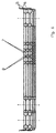
- the edges of the mostly rectangular plates are bowl-shaped above their levels and in the corners are embossed on Truncated cone openings formed.
- Your heat exchanger surfaces are profiled to reduce the turbulence of the heat exchange media flowing between the plates to increase and enlarge the heat exchanger surfaces.
- Adjacent plates in the stack are at 180 ° to each other in their levels rotated so that they are impressed at an acute angle to the axes of the plates Cross profiles, which keeps the panels at a distance become .
- the height of the profiles corresponds to half the thickness of the Flow gaps between the plates.
- the stacked plates are soldered or welded at the points of contact, or the plates are held together by screw connections and provided with seals at the edges.
- the flow gaps between the plates are alternately used water or heating water flows through.
- the counterflow is preferred, because there is a heat gradient over the entire length of the flow gap exists, when the fresh water enters the largely cooled Heating water and when the hot water emerges to the inflowing Heating water.
- EP 0 837 287 relates to such a plate heat exchanger, their four connections for heating water supply and return as well as for Fresh water supply and hot water discharge on one side of the plate stack are arranged. This makes installation in a thermal bath easier.
- Coaxial with the cold water inlet is a temperature-dependent NTC or PTC resistor arranged when the hot water is drawn on the incoming fresh water reacts and the heating device or the Heating water inflow activated.
- this monitoring device cannot ensure that warm water to the consumer when the tap is opened Is available and not cooled domestic water and that the domestic water does not exceed a target temperature. That can be done with the known prior art achieved only by a storage container be, the hot water temperature constantly by temperature sensor is monitored and regulated by means of a control unit. For one such a storage container is not sufficient in modern thermal baths Space available. Another problem is that the heating water cools between a water heater and the water heater and then cooled heating water first enters the storage tank. Both conventional storage tanks, this cold heating water mixes with the stored hot heating water and cools the stored hot domestic water below the permissible target temperature.
- the object of the invention is to design a plate heat exchanger in such a way that that it not only prepares hot water, but if it is observed a target temperature range, even if it is temporary cooled heating water flows in, so that when tapping always immediately Hot water is available in the desired temperature, which Legionella risk is averted and scale formation is avoided.
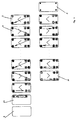
- a plate heat exchanger conventional design between its reinforced end plates another plate stack is arranged, the heat transfer plates differ from the first stack in that they are on the domestic water side have larger profiles and thus flow gaps than on the heating water side.
- On the end plate delimiting this stack are a or more temperature sensors arranged via a control unit Open the control valve for the inlet of heating water when the domestic water falls below a set point temperature, and it closes when the temperature exceeds another setpoint.
- the lower setpoint is preferred 45 ° C and chosen as the upper 60 ° C.
- Another effect is that short-term disturbances caused by feeding of chilled heating water can occur due to the in the plate heat exchanger stored hot domestic water can be bridged can .
- the stored hot water is not only by the Insulation surrounding the plate heat exchanger is protected from cooling down.
- the narrow flow gaps of the plate heat exchanger prevent that Mix cooled heating water with the stored warm heating water and cool it down. It also primarily serves as a memory Pile more hot domestic water stored than heating water. His Storage volume is dimensioned so that the hot domestic water stored in it sufficient for hot heating water to flow in.
- the additional effort for a second stack of heat transfer plates is partially in the plate heat exchanger according to the invention compensated by the fact that the heating water when dispensing hot water no cold process water, but already heated process water flows against.
- the heating water After passing through the first stack, the heating water becomes the second Stack fed to the end plate adjacent to it.
- the cold service water and the heating water return are on the first Stack passed.
- the heat transfer plates provided with six openings, except the last one Plate of the first stack and the first plate of the second stack, the five breakthroughs received, as well as the penultimate plate of the second stack with four and the last plate of the second stack with two openings.
- the circular openings are on truncated cones, which lead to the one or the other side of a heat exchanger plate are stamped.
Landscapes
- Engineering & Computer Science (AREA)
- Physics & Mathematics (AREA)
- Thermal Sciences (AREA)
- Mechanical Engineering (AREA)
- General Engineering & Computer Science (AREA)
- Heat-Exchange Devices With Radiators And Conduit Assemblies (AREA)
- Filling Or Discharging Of Gas Storage Vessels (AREA)
- Heat-Pump Type And Storage Water Heaters (AREA)
Applications Claiming Priority (2)
| Application Number | Priority Date | Filing Date | Title |
|---|---|---|---|
| DE19906180 | 1999-02-05 | ||
| DE19906180A DE19906180C2 (de) | 1999-02-05 | 1999-02-05 | Plattenwärmeübertrager für Warmwasserbereitung und -speicherung |
Publications (3)
| Publication Number | Publication Date |
|---|---|
| EP1026467A2 true EP1026467A2 (fr) | 2000-08-09 |
| EP1026467A3 EP1026467A3 (fr) | 2000-12-13 |
| EP1026467B1 EP1026467B1 (fr) | 2003-04-23 |
Family
ID=7897499
Family Applications (1)
| Application Number | Title | Priority Date | Filing Date |
|---|---|---|---|
| EP00250027A Expired - Lifetime EP1026467B1 (fr) | 1999-02-05 | 2000-01-27 | Echangeur de chaleur à plaques pour préparation et stockage d'eau chaude |
Country Status (3)
| Country | Link |
|---|---|
| EP (1) | EP1026467B1 (fr) |
| AT (1) | ATE238532T1 (fr) |
| DE (2) | DE19906180C2 (fr) |
Cited By (2)
| Publication number | Priority date | Publication date | Assignee | Title |
|---|---|---|---|---|
| JP2003517558A (ja) * | 1999-12-15 | 2003-05-27 | スウエプ インターナシヨナル アーベー | 板状熱交換器と温水貯蔵コンテナを備える湯沸器 |
| WO2003046461A1 (fr) * | 2001-11-23 | 2003-06-05 | Rotartica, S.A. | Echangeur thermique a plaques |
Families Citing this family (4)
| Publication number | Priority date | Publication date | Assignee | Title |
|---|---|---|---|---|
| DE10001065C2 (de) * | 2000-01-13 | 2002-11-21 | Ballard Power Systems | Plattenstapel-Wärmeübertrager, insbesondere zur Verwendung als Reformierungsreaktor |
| DE10049890B4 (de) * | 2000-10-10 | 2007-02-22 | Behr Gmbh & Co. Kg | Stapelscheiben-Wärmeübertrager |
| DE10320812B4 (de) * | 2003-05-08 | 2007-03-01 | Gea Wtt Gmbh | Plattenwärmeübertrager mit einwandigen und doppelwandigen Wärmeübertragerplatten |
| JP2018084393A (ja) * | 2016-11-25 | 2018-05-31 | 株式会社ノーリツ | 熱交換器及び貯湯給湯装置 |
Citations (11)
| Publication number | Priority date | Publication date | Assignee | Title |
|---|---|---|---|---|
| DE2214711A1 (de) | 1972-03-25 | 1973-10-04 | Egon Laforce | Heisswasserbereiter |
| DE2605994A1 (de) | 1976-02-14 | 1977-08-25 | Baelz Gmbh Helmut | Warmwasserbereitungsanlage |
| EP0178351A1 (fr) | 1984-10-15 | 1986-04-23 | Plaatverwerkende Industrie van Wijk en Boerma B.V. | Chauffe-eau, par exemple chaudière d'eau sanitaire |
| DE3622139A1 (de) | 1986-07-02 | 1988-01-21 | Albert Gohl Sanitaere Anlagen | Wasserversorgungsanlage |
| DE4035115A1 (de) | 1990-03-12 | 1991-09-19 | Sandler Energietechnik | Anordnung zur entnahme von warmen oder heissem brauchwasser von trinkwasserqualitaet aus einer heizanlage |
| EP0602349A1 (fr) | 1992-12-12 | 1994-06-22 | VIESSMANN WERKE GmbH & CO. | Accumulateur à enveloppe double pour la préparation et accumulation d'eau chaude sanitaire |
| DE4300292A1 (de) | 1993-01-08 | 1994-07-14 | C T C Waermetauscher Gmbh | Warmwasserversorgung |
| EP0819892A2 (fr) | 1996-07-17 | 1998-01-21 | KME Schmöle GmbH | Echangeur de chaleur pour la production d'eau sanitaire |
| EP0825386A2 (fr) | 1996-08-20 | 1998-02-25 | Robert Bosch Gmbh | Accumulateur d'eau chaude |
| EP0837287A2 (fr) | 1996-10-16 | 1998-04-22 | Joh. Vaillant GmbH u. Co. | Chauffe-eau sanitaire |
| DE19721745C1 (de) | 1997-05-24 | 1998-11-05 | Viessmann Werke Kg | Speicher-Durchlauferhitzer |
Family Cites Families (6)
| Publication number | Priority date | Publication date | Assignee | Title |
|---|---|---|---|---|
| AT393162B (de) * | 1987-07-13 | 1991-08-26 | Broeckl Gerhard Ing | Plattenwaermeaustauscher mit besonderem profil der waermeaustauschzone |
| IT1263611B (it) * | 1993-02-19 | 1996-08-27 | Giannoni Srl | Scambiatore di calore a piastre |
| IT1271978B (it) * | 1993-03-05 | 1997-06-10 | Giannoni Srl | Gruppo scambiatore a piastre dispositivo di controllo e relativo scambiatore. |
| DE9421058U1 (de) * | 1994-01-20 | 1995-03-23 | Viessmann Werke Gmbh & Co, 35108 Allendorf | Durchflußwärmetauscher, insbesondere Brauchwasserspeicher |
| DE4431413C2 (de) * | 1994-08-24 | 2002-10-10 | Rehberg Michael | Plattenwärmetauscher für flüssige und gasförmige Medien |
| DE59600935D1 (de) * | 1995-05-10 | 1999-01-21 | Laengerer & Reich Gmbh & Co | Plattenwärmetauscher |
-
1999
- 1999-02-05 DE DE19906180A patent/DE19906180C2/de not_active Expired - Lifetime
-
2000
- 2000-01-27 AT AT00250027T patent/ATE238532T1/de not_active IP Right Cessation
- 2000-01-27 EP EP00250027A patent/EP1026467B1/fr not_active Expired - Lifetime
- 2000-01-27 DE DE50001824T patent/DE50001824D1/de not_active Expired - Lifetime
Patent Citations (11)
| Publication number | Priority date | Publication date | Assignee | Title |
|---|---|---|---|---|
| DE2214711A1 (de) | 1972-03-25 | 1973-10-04 | Egon Laforce | Heisswasserbereiter |
| DE2605994A1 (de) | 1976-02-14 | 1977-08-25 | Baelz Gmbh Helmut | Warmwasserbereitungsanlage |
| EP0178351A1 (fr) | 1984-10-15 | 1986-04-23 | Plaatverwerkende Industrie van Wijk en Boerma B.V. | Chauffe-eau, par exemple chaudière d'eau sanitaire |
| DE3622139A1 (de) | 1986-07-02 | 1988-01-21 | Albert Gohl Sanitaere Anlagen | Wasserversorgungsanlage |
| DE4035115A1 (de) | 1990-03-12 | 1991-09-19 | Sandler Energietechnik | Anordnung zur entnahme von warmen oder heissem brauchwasser von trinkwasserqualitaet aus einer heizanlage |
| EP0602349A1 (fr) | 1992-12-12 | 1994-06-22 | VIESSMANN WERKE GmbH & CO. | Accumulateur à enveloppe double pour la préparation et accumulation d'eau chaude sanitaire |
| DE4300292A1 (de) | 1993-01-08 | 1994-07-14 | C T C Waermetauscher Gmbh | Warmwasserversorgung |
| EP0819892A2 (fr) | 1996-07-17 | 1998-01-21 | KME Schmöle GmbH | Echangeur de chaleur pour la production d'eau sanitaire |
| EP0825386A2 (fr) | 1996-08-20 | 1998-02-25 | Robert Bosch Gmbh | Accumulateur d'eau chaude |
| EP0837287A2 (fr) | 1996-10-16 | 1998-04-22 | Joh. Vaillant GmbH u. Co. | Chauffe-eau sanitaire |
| DE19721745C1 (de) | 1997-05-24 | 1998-11-05 | Viessmann Werke Kg | Speicher-Durchlauferhitzer |
Cited By (4)
| Publication number | Priority date | Publication date | Assignee | Title |
|---|---|---|---|---|
| JP2003517558A (ja) * | 1999-12-15 | 2003-05-27 | スウエプ インターナシヨナル アーベー | 板状熱交換器と温水貯蔵コンテナを備える湯沸器 |
| EP1238231B2 (fr) † | 1999-12-15 | 2007-05-16 | SWEP International AB | Chauffe-eau comprenant un echangeur a plaques et un reservoir d'eau chaude |
| WO2003046461A1 (fr) * | 2001-11-23 | 2003-06-05 | Rotartica, S.A. | Echangeur thermique a plaques |
| ES2188415A1 (es) * | 2001-11-23 | 2003-06-16 | Rotartica S A | Termocambiador compacto de placas. |
Also Published As
| Publication number | Publication date |
|---|---|
| EP1026467A3 (fr) | 2000-12-13 |
| ATE238532T1 (de) | 2003-05-15 |
| DE50001824D1 (de) | 2003-05-28 |
| DE19906180C2 (de) | 2003-02-06 |
| DE19906180A1 (de) | 2000-08-10 |
| EP1026467B1 (fr) | 2003-04-23 |
Similar Documents
| Publication | Publication Date | Title |
|---|---|---|
| EP1559980B1 (fr) | Echangeur de chaleur à plaques | |
| AT510440B1 (de) | Fluidspeicher | |
| EP3911907B1 (fr) | Dispositif et procédé pour la récupération de chaleur d'un milieu liquide | |
| EP1936297A2 (fr) | Cartouche pour un accumulateur stratifié | |
| EP3098553B1 (fr) | Systeme d'echangeur thermique a plaques | |
| EP1026467B1 (fr) | Echangeur de chaleur à plaques pour préparation et stockage d'eau chaude | |
| AT400984B (de) | Vorrichtung zum erwärmen von brauchwasser mit hilfe eines heizmediums | |
| WO2012038046A2 (fr) | Échangeur de chaleur | |
| DE102007054703B4 (de) | Wärmetauscher | |
| EP2481991A2 (fr) | Collecteur et distributeur pour une installation de chauffage ou de refroidissement | |
| EP2059750A2 (fr) | Appareil de réfrigération à réservoir d'eau | |
| EP2618071A2 (fr) | Accumulateur stratifié | |
| DE202015101978U1 (de) | Speichertank mit Strömungsleitelement | |
| EP0557994B1 (fr) | Dispositif pour la production d'eau chaude à économie d'énergie | |
| DE202015004676U1 (de) | Warmwasser-Schichtenspeicher | |
| WO2013120621A2 (fr) | Échangeur de chaleur pour une installation de chauffage ou un système de fourniture de chaleur | |
| DE102010018086B4 (de) | Wärmeübertragungseinrichtung | |
| DE3211376C2 (fr) | ||
| DE102021134317A1 (de) | Fernwärmeübergabestation und verfahren zum betreiben derselben | |
| DE3115697C2 (fr) | ||
| EP0972994B1 (fr) | Appareil de chauffage pour eau chaude sanitaire | |
| DE2530952A1 (de) | Mit abwasserwaerme beheizter warmwasserbereiter | |
| AT402561B (de) | Vorrichtung zum erwärmen von brauchwasser | |
| EP1724415A2 (fr) | Accumulateur controllé avec deux zones pour la préparation d'eau chaude sanitaire fraîche | |
| DE8911523U1 (de) | Vorrichtung zum Erwärmen oder Kühlen von Flüssigkeiten |
Legal Events
| Date | Code | Title | Description |
|---|---|---|---|
| PUAI | Public reference made under article 153(3) epc to a published international application that has entered the european phase |
Free format text: ORIGINAL CODE: 0009012 |
|
| AK | Designated contracting states |
Kind code of ref document: A2 Designated state(s): AT BE CH CY DE DK ES FI FR GB GR IE IT LI LU MC NL PT SE |
|
| AX | Request for extension of the european patent |
Free format text: AL;LT;LV;MK;RO;SI |
|
| PUAL | Search report despatched |
Free format text: ORIGINAL CODE: 0009013 |
|
| AK | Designated contracting states |
Kind code of ref document: A3 Designated state(s): AT BE CH CY DE DK ES FI FR GB GR IE IT LI LU MC NL PT SE |
|
| AX | Request for extension of the european patent |
Free format text: AL;LT;LV;MK;RO;SI |
|
| K1C3 | Correction of patent application (complete document) published |
Effective date: 20001213 |
|
| 17P | Request for examination filed |
Effective date: 20010108 |
|
| AKX | Designation fees paid |
Free format text: AT BE CH CY DE DK ES FI FR GB GR IE IT LI LU MC NL PT SE |
|
| GRAH | Despatch of communication of intention to grant a patent |
Free format text: ORIGINAL CODE: EPIDOS IGRA |
|
| GRAH | Despatch of communication of intention to grant a patent |
Free format text: ORIGINAL CODE: EPIDOS IGRA |
|
| GRAA | (expected) grant |
Free format text: ORIGINAL CODE: 0009210 |
|
| AK | Designated contracting states |
Designated state(s): AT BE CH CY DE DK ES FI FR GB GR IE IT LI LU MC NL PT SE |
|
| PG25 | Lapsed in a contracting state [announced via postgrant information from national office to epo] |
Ref country code: IT Free format text: LAPSE BECAUSE OF FAILURE TO SUBMIT A TRANSLATION OF THE DESCRIPTION OR TO PAY THE FEE WITHIN THE PRESCRIBED TIME-LIMIT;WARNING: LAPSES OF ITALIAN PATENTS WITH EFFECTIVE DATE BEFORE 2007 MAY HAVE OCCURRED AT ANY TIME BEFORE 2007. THE CORRECT EFFECTIVE DATE MAY BE DIFFERENT FROM THE ONE RECORDED. Effective date: 20030423 Ref country code: NL Free format text: LAPSE BECAUSE OF FAILURE TO SUBMIT A TRANSLATION OF THE DESCRIPTION OR TO PAY THE FEE WITHIN THE PRESCRIBED TIME-LIMIT Effective date: 20030423 Ref country code: GB Free format text: LAPSE BECAUSE OF FAILURE TO SUBMIT A TRANSLATION OF THE DESCRIPTION OR TO PAY THE FEE WITHIN THE PRESCRIBED TIME-LIMIT Effective date: 20030423 Ref country code: CY Free format text: LAPSE BECAUSE OF FAILURE TO SUBMIT A TRANSLATION OF THE DESCRIPTION OR TO PAY THE FEE WITHIN THE PRESCRIBED TIME-LIMIT Effective date: 20030423 Ref country code: FR Free format text: LAPSE BECAUSE OF FAILURE TO SUBMIT A TRANSLATION OF THE DESCRIPTION OR TO PAY THE FEE WITHIN THE PRESCRIBED TIME-LIMIT Effective date: 20030423 Ref country code: IE Free format text: LAPSE BECAUSE OF NON-PAYMENT OF DUE FEES Effective date: 20030423 Ref country code: FI Free format text: LAPSE BECAUSE OF FAILURE TO SUBMIT A TRANSLATION OF THE DESCRIPTION OR TO PAY THE FEE WITHIN THE PRESCRIBED TIME-LIMIT Effective date: 20030423 |
|
| REG | Reference to a national code |
Ref country code: GB Ref legal event code: FG4D Free format text: NOT ENGLISH |
|
| REG | Reference to a national code |
Ref country code: CH Ref legal event code: EP |
|
| REF | Corresponds to: |
Ref document number: 50001824 Country of ref document: DE Date of ref document: 20030528 Kind code of ref document: P |
|
| REG | Reference to a national code |
Ref country code: IE Ref legal event code: FG4D Free format text: GERMAN |
|
| PG25 | Lapsed in a contracting state [announced via postgrant information from national office to epo] |
Ref country code: GR Free format text: LAPSE BECAUSE OF FAILURE TO SUBMIT A TRANSLATION OF THE DESCRIPTION OR TO PAY THE FEE WITHIN THE PRESCRIBED TIME-LIMIT Effective date: 20030723 Ref country code: DK Free format text: LAPSE BECAUSE OF FAILURE TO SUBMIT A TRANSLATION OF THE DESCRIPTION OR TO PAY THE FEE WITHIN THE PRESCRIBED TIME-LIMIT Effective date: 20030723 Ref country code: PT Free format text: LAPSE BECAUSE OF FAILURE TO SUBMIT A TRANSLATION OF THE DESCRIPTION OR TO PAY THE FEE WITHIN THE PRESCRIBED TIME-LIMIT Effective date: 20030723 Ref country code: SE Free format text: LAPSE BECAUSE OF FAILURE TO SUBMIT A TRANSLATION OF THE DESCRIPTION OR TO PAY THE FEE WITHIN THE PRESCRIBED TIME-LIMIT Effective date: 20030723 |
|
| NLV1 | Nl: lapsed or annulled due to failure to fulfill the requirements of art. 29p and 29m of the patents act | ||
| PG25 | Lapsed in a contracting state [announced via postgrant information from national office to epo] |
Ref country code: ES Free format text: LAPSE BECAUSE OF FAILURE TO SUBMIT A TRANSLATION OF THE DESCRIPTION OR TO PAY THE FEE WITHIN THE PRESCRIBED TIME-LIMIT Effective date: 20031030 |
|
| REG | Reference to a national code |
Ref country code: IE Ref legal event code: FD4D Ref document number: 1026467E Country of ref document: IE |
|
| GBT | Gb: translation of ep patent filed (gb section 77(6)(a)/1977) |
Effective date: 20031204 |
|
| PG25 | Lapsed in a contracting state [announced via postgrant information from national office to epo] |
Ref country code: AT Free format text: LAPSE BECAUSE OF NON-PAYMENT OF DUE FEES Effective date: 20040127 Ref country code: LU Free format text: LAPSE BECAUSE OF NON-PAYMENT OF DUE FEES Effective date: 20040127 |
|
| PG25 | Lapsed in a contracting state [announced via postgrant information from national office to epo] |
Ref country code: CH Free format text: LAPSE BECAUSE OF NON-PAYMENT OF DUE FEES Effective date: 20040131 Ref country code: BE Free format text: LAPSE BECAUSE OF NON-PAYMENT OF DUE FEES Effective date: 20040131 Ref country code: MC Free format text: LAPSE BECAUSE OF NON-PAYMENT OF DUE FEES Effective date: 20040131 Ref country code: LI Free format text: LAPSE BECAUSE OF NON-PAYMENT OF DUE FEES Effective date: 20040131 |
|
| NLXE | Nl: other communications concerning ep-patents (part 3 heading xe) |
Free format text: A REQUEST FOR RESTORATION TO THE PRIOR STATE (ARTICLE 23 OF THE PATENTS ACT 1995 HAS BEEN FILED ON 20031118. |
|
| PLBE | No opposition filed within time limit |
Free format text: ORIGINAL CODE: 0009261 |
|
| STAA | Information on the status of an ep patent application or granted ep patent |
Free format text: STATUS: NO OPPOSITION FILED WITHIN TIME LIMIT |
|
| 26N | No opposition filed |
Effective date: 20040126 |
|
| EN | Fr: translation not filed | ||
| NLXE | Nl: other communications concerning ep-patents (part 3 heading xe) |
Free format text: A REQUEST FOR RESTORATION TO THE PRIOR STATE AS PROVIDED FOR IN ARTICLE 23 OF THE PATENTS ACT 1995 (SEE PUBLICATION IN HEADING XE OF THE PATENT BULLETIN OF 20040202/02) HAS BEEN GRANTED; THE RESTORATION OF THE PATENT HAS BEEN ENTERED IN THE PATENT REGISTER. |
|
| BERE | Be: lapsed |
Owner name: PATENTE *REHBERG LAUER Effective date: 20040131 |
|
| GBPC | Gb: european patent ceased through non-payment of renewal fee |
Effective date: 20040127 |
|
| REG | Reference to a national code |
Ref country code: CH Ref legal event code: PL |
|
| PGFP | Annual fee paid to national office [announced via postgrant information from national office to epo] |
Ref country code: NL Payment date: 20080531 Year of fee payment: 10 |
|
| REG | Reference to a national code |
Ref country code: NL Ref legal event code: V1 Effective date: 20100801 |
|
| PG25 | Lapsed in a contracting state [announced via postgrant information from national office to epo] |
Ref country code: NL Free format text: LAPSE BECAUSE OF NON-PAYMENT OF DUE FEES Effective date: 20100801 |
|
| PGFP | Annual fee paid to national office [announced via postgrant information from national office to epo] |
Ref country code: DE Payment date: 20190131 Year of fee payment: 20 |
|
| REG | Reference to a national code |
Ref country code: DE Ref legal event code: R071 Ref document number: 50001824 Country of ref document: DE |