EP0973013A1 - Capteur de déplacement - Google Patents
Capteur de déplacement Download PDFInfo
- Publication number
- EP0973013A1 EP0973013A1 EP99107692A EP99107692A EP0973013A1 EP 0973013 A1 EP0973013 A1 EP 0973013A1 EP 99107692 A EP99107692 A EP 99107692A EP 99107692 A EP99107692 A EP 99107692A EP 0973013 A1 EP0973013 A1 EP 0973013A1
- Authority
- EP
- European Patent Office
- Prior art keywords
- analog
- scanning
- incremental track
- signal
- output signal
- Prior art date
- Legal status (The legal status is an assumption and is not a legal conclusion. Google has not performed a legal analysis and makes no representation as to the accuracy of the status listed.)
- Granted
Links
- 238000006073 displacement reaction Methods 0.000 title claims description 15
- 238000000034 method Methods 0.000 claims abstract description 44
- 238000005070 sampling Methods 0.000 claims description 23
- 230000005670 electromagnetic radiation Effects 0.000 claims description 8
- 238000012545 processing Methods 0.000 claims description 8
- 238000012937 correction Methods 0.000 claims description 5
- 230000000630 rising effect Effects 0.000 claims description 4
- 230000010363 phase shift Effects 0.000 claims description 2
- 230000001105 regulatory effect Effects 0.000 claims description 2
- 230000004075 alteration Effects 0.000 abstract 2
- 238000011161 development Methods 0.000 description 11
- 230000018109 developmental process Effects 0.000 description 11
- 238000005259 measurement Methods 0.000 description 10
- 230000001965 increasing effect Effects 0.000 description 7
- 238000001514 detection method Methods 0.000 description 3
- 230000005693 optoelectronics Effects 0.000 description 3
- 241000614201 Adenocaulon bicolor Species 0.000 description 1
- 230000032683 aging Effects 0.000 description 1
- 238000006243 chemical reaction Methods 0.000 description 1
- 230000001419 dependent effect Effects 0.000 description 1
- 238000013461 design Methods 0.000 description 1
- 238000010586 diagram Methods 0.000 description 1
- 238000004090 dissolution Methods 0.000 description 1
- 230000000763 evoking effect Effects 0.000 description 1
- 230000006698 induction Effects 0.000 description 1
- 238000004519 manufacturing process Methods 0.000 description 1
- 238000000691 measurement method Methods 0.000 description 1
- 230000035945 sensitivity Effects 0.000 description 1
- 238000003860 storage Methods 0.000 description 1
- 238000005494 tarnishing Methods 0.000 description 1
- 230000001960 triggered effect Effects 0.000 description 1
Images


Classifications
-
- G—PHYSICS
- G01—MEASURING; TESTING
- G01D—MEASURING NOT SPECIALLY ADAPTED FOR A SPECIFIC VARIABLE; ARRANGEMENTS FOR MEASURING TWO OR MORE VARIABLES NOT COVERED IN A SINGLE OTHER SUBCLASS; TARIFF METERING APPARATUS; MEASURING OR TESTING NOT OTHERWISE PROVIDED FOR
- G01D5/00—Mechanical means for transferring the output of a sensing member; Means for converting the output of a sensing member to another variable where the form or nature of the sensing member does not constrain the means for converting; Transducers not specially adapted for a specific variable
- G01D5/12—Mechanical means for transferring the output of a sensing member; Means for converting the output of a sensing member to another variable where the form or nature of the sensing member does not constrain the means for converting; Transducers not specially adapted for a specific variable using electric or magnetic means
- G01D5/244—Mechanical means for transferring the output of a sensing member; Means for converting the output of a sensing member to another variable where the form or nature of the sensing member does not constrain the means for converting; Transducers not specially adapted for a specific variable using electric or magnetic means influencing characteristics of pulses or pulse trains; generating pulses or pulse trains
- G01D5/24409—Interpolation using memories
Definitions
- the present invention relates to a method for measuring a path change of a movable part relative to one fixed reference point at which one with the moving part connected incremental track at the reference point digital is scanned and from the result of the digital sampling an output signal is generated which is a measure of the Change of path is.
- the present invention also relates to a displacement sensor for measuring a change in displacement of a movable Partly relative to a fixed reference point that is at least one incremental track connected to the moving part, one on the Digital scanning unit arranged as a reference point, which the Digitally scans incremental track, and a processing unit which processes the digital sampling signal and an output signal from the result of the digital sampling generated, which is a measure of the path change.
- a position sensor can also be used as an angle sensor for measuring the change in angle of a sensor disk.
- ⁇ 360 ° 2 ⁇ R ⁇ s
- Angle encoders are used, for example, in the field of Automotive technology used as steering angle sensors.
- the Angle information is recorded under interrupt control.
- the Interrupts are via the incremental track of the encoder disc triggered and signal that the encoder disc continues to rotate around a certain angle value.
- This angle value determines the Resolution and thus the accuracy of the steering angle sensor.
- the data output from the steering angle sensor such as the change in angle and the angular velocity are in a certain time, for example over a real-time capable bus (CAN), issued for further processing. Due to the given resolution and the speed of the Angle change becomes the timing of the output of the output Dates set. The greater the resolution and the lower the The speed of the angle change is, the longer the Time cycle can be selected.
- the known steering angle sensors have the disadvantage that they have a relatively low resolution. This causes the Data output from the steering angle sensor for certain applications do not have the required accuracy exhibit. In addition, with a rough resolution in Connection at a low speed the Angle change the data to be output from the steering angle sensor can only be updated in a very long time cycle, whereby the accuracy of further processing is essential is affected.
- the object of the present invention is therefore to the procedure of the type mentioned in this regard to train that the resolution of the measurement of a Path change is significantly increased to thereby Accuracy of measuring a change in path increase and The cycle time for the output of the data to be output is reduced can.
- the method according to the invention achieves the above object by the features of claim 1. According to that Generic methods for Measuring a path change designed so that the digital Scanning for rough determination of the change of path serves and that for Fine determination of the path change the incremental track on the Reference point is scanned analog and the output signal corrected using the result of the analog sampling becomes.
- the resolution of the Measurement of a change in path can be significantly increased can that first a rough determination of the change in path is carried out and the measured value of the rough determination then by means of the measured value of the fine determination is corrected.
- the incremental track next to the Measurement of the path change using digital scanning also the Fine determination of the measured value for the path change carried out.
- the Incremental track scanned analog. The output signal that First the result of the rough determination is then corrected using the result of the analog sampling.
- Coding is applied to the incremental track, the repeats itself within a certain period.
- the signal the analog sampling is repeated within this Period.
- For the rough determination of the change of route are in the frame the digital sampling the individual gaps in the coding Counted depending on the direction of movement.
- the dissolution of the Rough determination corresponds to the coding period of the Incremental track.
- the result of the digital scan, namely the sum of the gaps counted gives a first value for the path change.
- the incremental track also scanned analog.
- the analog sampling delivers within the period in which the result of the rough determination lies, a relative value for the path change. Within that period can the path change through the fine determination with a determine much higher resolution than that in the context of Rough determination would be possible.
- Measurement method can change the path and the speed of the Path change determined with a much better accuracy become.
- the clock rate for output the data to be output such as the change in angle and the Angular velocity can be increased significantly, d. H. the individual periods between the output of data can be significantly shortened. This can reduce the accuracy of the Further processing of the data can be increased significantly.
- coding on the incremental track is upset within a certain period repeated and that the signal of analog sampling Characteristic value for the relative path change within this Period is assigned from a look-up table.
- the Characteristic values in the look-up table advantageously have a higher resolution than the resolution of the rough determination.
- the corrected output signal is the sum of the result the digital sampling and the characteristic value.
- Incremental track only scanned analog and that Analog scan signal for digital scan digitized. In this way, a digital scanning unit be saved. It is necessary to scan the incremental track just a single scanning unit that has an analog signal delivers. The analog signal is digitized and then used for Rough determination of the path change used. For fine determination the analog signal is used immediately. The signal the analog scanning is advantageously carried out by means of a A / D converter digitized.
- the analog sampling using at least an electromagnetic radiation source and at least one Receiver for electromagnetic radiation takes place.
- the analog scanning is advantageously carried out by means of two electromagnetic radiation sources, each one Assigned to receivers for electromagnetic radiation where the analog individual signals of the receiver to the signal of the analog sampling can be added.
- the coding of the Incremental track can, for example, inductively by means of a magnetic coding on the incremental track and one Induction coil, magnetic by means of a magnetic Coding on the incremental track and a magnetic sensor or optoelectronic.
- the optoelectronic scanning of the coding of the Incremental track is advantageously carried out by means of two Light sources and two light sensors.
- the use of infrared light emitting diodes (IR-LED) as light sources for the analog Scanning is particularly advantageous.
- As light sensors for the Analog scanning advantageously becomes photo transistors used.
- the light sources and the light sources assigned light sensors on the same side of the To arrange incremental track In this case the measurement in the reflected light.
- the Light sources and those assigned to the light sources However, light sensors on opposite sides of the Incremental track arranged. In this case the measurement is carried out in the continuous light.
- the analog individual signals of the two sensor elements are added to form an analog sum signal.
- This so-called area detection is necessary because information is lost when the two analog single signals are added to the analog sum signal, ie two characteristic values are stored in the look-up table for each value of the analog sum signal.
- the two analog individual signals are evaluated with regard to their amplitudes.
- the value of the analog sum signal, to which a corresponding characteristic value is to be assigned is in a first area of the analog sum signal or in one second area.
- a unique characteristic value can be assigned to a value of the analog sum signal by the range detection. Since the analog sum signal has a symmetrical signal curve, it is sufficient if the characteristic curve values of half a period of the coding of the incremental track are stored in the look-up table. When selecting the characteristic curve values to be stored in the look-up table, however, care must be taken that those characteristic curve values are saved from which the characteristic curve values of the entire analog sum signal can be determined. This is the case when the characteristic values are stored between two successive maxima V max or minima V min of the sum signal. This measure can reduce the storage effort for the look-up table by half.
- the Offset between fine determination and rough determination of the Path change is subtracted.
- the offset has its cause in Manufacturing tolerances as well as tolerances in the digital Scanning.
- the offset is advantageously thereby determines that the measured value of the fine determination with the measured value of the rough determination is then compared if the digitized signal of analog sampling is increasing Has flank.
- the characteristics of the receivers are regulated dynamically, that the recipients always work at their working point.
- Either the photo transistor as well as the IR LED are strong temperature dependent.
- the radiance of the IR LED and the Sensitivity of the phototransistor increases over the lifetime from. The decrease is caused by fogging or tarnishing Plastic lenses evoked.
- To the influences of Compensate for temperature fluctuations and the aging process To be able to do this requires dynamic characteristic control. she should in particular drift away the characteristic of the Photo transistor from the operating point of the photo transistor prevent.
- the position of the maxima of the individual analog signals is determined the maxima compared to a setpoint and at a Difference between actual and target value a correction carried out.
- the correction is advantageously carried out by Shift the characteristic of the receiver to the working point of the receiver by changing the IR LED current.
- the IR LED currents advantageously stored. After starting a new one Measurement process, these stored values of the IR LED currents as initial values for dynamic characteristic control be used.
- the signals of the analog sampling using a low-pass filter smoothed advantageously has a cut-off frequency of approximately ten times the highest Frequency of the signals of the analog sampling.
- the threshold value is advantageously equal to one third selected the maximum resolution of the rough determination.
- the present invention is also based on the object a path encoder for measuring changes in the path at the beginning the kind mentioned in such a way that the resolution the measurement of a path change is significantly increased in order thereby increasing the accuracy of the measurement of a path change and the cycle time for the output of the data to be output to be able to reduce.
- the displacement sensor according to the invention solves the above task by the features of claim 28 Generic pathfinders for measuring already discussed at the beginning a path change designed so that the path encoder has analog scanning unit that the incremental track analog samples that the processing unit receives the signal of the analog Processing processed and that the encoder a Correction unit, which uses the output signal Corrected analog sampling result.
- the travel sensor according to the invention is advantageously as Angle encoder designed, in particular as a steering angle sensor for Determination of steering wheel lock in motor vehicles.
- a displacement sensor according to the invention is shown in a detail in a first embodiment.
- the displacement sensor shown is designed as a steering angle sensor for determining the steering wheel lock in motor vehicles.
- the steering angle sensor is used to measure a change in angle of an encoder disk connected to a steering wheel of a motor vehicle.
- An incremental track 1 is arranged on the encoder disk, which is scanned by a scanning unit 2.
- the optoelectronic scanning unit 2 has two sensor elements 3, 4, which in turn each consist of an infrared light-emitting diode 5 and a photo transistor 6.
- the coding of incremental track 1 is scanned analogous.
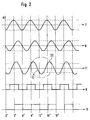
- Each of the sensor elements 3, 4 provides an analog one Individual signal 7, 8 (see FIG. 2) with the period of the coding. Due to the positioning of the two sensor elements 3, 4 to each other, the two analog single signals 7, 8 are 4.5 ° out of phase with each other.
- the result of the rough determination is corrected by a fine determination.
- the two individual signals 7, 8 are added to an analog sum signal 11.
- the period of the sum signal 11 in the area of the result of the rough determination is shown enlarged in FIG. 3.
- the relative angle within the period shown is shown on the abscissa.
- the relative angle of 0 ° would correspond to a value of the absolute change in angle of 9.75 ° (the maximum V max of the sum signal 11 is exactly between 9 ° and 10.5 °).
- the amplitude is plotted on the ordinate.
- a characteristic value 13 from a stored look-up table is assigned to the amplitude value 12 of the sum signal 11.
- the amplitude value A of the first analog single signal 7 is compared with the amplitude value A of the second analog single signal 8.
- the characteristic value 13 is in the range 1, and the result of the fine determination is 2 °.
- the corrected output signal must namely because of the result the rough determination (10.5 °) and the resolution of the rough determination (1.5 °) are in the range between 10.5 ° and 12 °.
- As part of A plausibility check determines whether this Condition is met. In the present case, the condition is fulfilled and the corrected output signal (11.75 °) spent. If the condition was not met, it would Result of the rough determination (10.5 °) are output.
Landscapes
- Physics & Mathematics (AREA)
- General Physics & Mathematics (AREA)
- Optical Transform (AREA)
- Length Measuring Devices With Unspecified Measuring Means (AREA)
Applications Claiming Priority (2)
| Application Number | Priority Date | Filing Date | Title |
|---|---|---|---|
| DE19831960 | 1998-07-16 | ||
| DE19831960A DE19831960A1 (de) | 1998-07-16 | 1998-07-16 | Wegsensor |
Publications (2)
| Publication Number | Publication Date |
|---|---|
| EP0973013A1 true EP0973013A1 (fr) | 2000-01-19 |
| EP0973013B1 EP0973013B1 (fr) | 2002-01-02 |
Family
ID=7874258
Family Applications (1)
| Application Number | Title | Priority Date | Filing Date |
|---|---|---|---|
| EP99107692A Expired - Lifetime EP0973013B1 (fr) | 1998-07-16 | 1999-04-17 | Capteur de déplacement |
Country Status (3)
| Country | Link |
|---|---|
| EP (1) | EP0973013B1 (fr) |
| DE (2) | DE19831960A1 (fr) |
| ES (1) | ES2166627T3 (fr) |
Cited By (1)
| Publication number | Priority date | Publication date | Assignee | Title |
|---|---|---|---|---|
| EP3494362A4 (fr) * | 2016-08-02 | 2020-03-11 | Servosense (SMC) Ltd. | Codeur absolu haute résolution |
Families Citing this family (2)
| Publication number | Priority date | Publication date | Assignee | Title |
|---|---|---|---|---|
| DE19954697C2 (de) * | 1999-11-13 | 2002-12-12 | Kostal Leopold Gmbh & Co Kg | Verfahren zum Korrigieren des digitalen oder digitalisierten Signals eines Weg- oder Winkelaufnehmers |
| DE10058623A1 (de) * | 2000-11-25 | 2002-06-13 | Daimler Chrysler Ag | Verfahren zur Ermittlung der Winkellage einer drehbaren Welle und Vorrichtung zur Durchführung des Verfahrens |
Citations (4)
| Publication number | Priority date | Publication date | Assignee | Title |
|---|---|---|---|---|
| EP0490206A1 (fr) * | 1990-12-10 | 1992-06-17 | Tesa S.A. | Capteur de position pour un appareil de mesure de grandeurs linéaires ou angulaires |
| DE4419050A1 (de) * | 1993-06-01 | 1994-12-08 | Nikon Corp | Positionsmessvorrichtung |
| EP0724137A1 (fr) * | 1995-01-30 | 1996-07-31 | Sony Magnescale, Inc. | Appareil d'interpolation |
| DE19545999A1 (de) * | 1995-12-09 | 1997-06-12 | Aeg Energietechnik Gmbh | Inkrementaler Stellungsgeber |
Family Cites Families (15)
| Publication number | Priority date | Publication date | Assignee | Title |
|---|---|---|---|---|
| DE3024716C2 (de) * | 1980-06-30 | 1986-10-23 | Dr. Johannes Heidenhain Gmbh, 8225 Traunreut | Digitales Längen- oder Winkelmeßsystem |
| DE3737720C2 (de) * | 1987-11-06 | 1995-02-09 | Heidenhain Gmbh Dr Johannes | Positionsmeßeinrichtung mit Unterteilungsschaltung |
| DE3738546C2 (de) * | 1987-11-13 | 1995-03-23 | Heidenhain Gmbh Dr Johannes | Positionsmeßeinrichtung mit Unterteilungsschaltung |
| DE3742329C1 (de) * | 1987-12-14 | 1989-03-30 | Heidenhain Gmbh Dr Johannes | Positionsmesseinrichtung mit Unterteilungsschaltung |
| US4996657A (en) * | 1988-03-18 | 1991-02-26 | Honda Giken Kogyo K.K. | Steering angle detecting system for automotive vehicles |
| DD273889A1 (de) * | 1988-07-11 | 1989-11-29 | Zeiss Jena Veb Carl | Verfahren und einrichtung zur interpolation sinusfoermiger messsignale, insbesondere solcher von fotoelektrischen messsystemen |
| JP2515891B2 (ja) * | 1989-09-20 | 1996-07-10 | 株式会社日立製作所 | 角度センサ及びトルクセンサ、そのセンサの出力に応じて制御される電動パワ―ステアリング装置 |
| DE4217498C2 (de) * | 1992-05-27 | 1995-10-26 | Bodenseewerk Geraetetech | Winkelgeber |
| DE4220502C1 (de) * | 1992-06-23 | 1993-12-16 | Stegmann Max Antriebstech | Drehwinkelmeßsystem |
| DE4228719A1 (de) * | 1992-08-28 | 1994-03-03 | Schaeffler Waelzlager Kg | Kapazitiver Lenkwinkelsensor für ein Kraftfahrzeug |
| DE4331151C2 (de) * | 1993-09-14 | 1997-05-22 | Baumueller Nuernberg Gmbh | System zur Messung der Absolutposition des beweglichen, zyklischen Teilungsmarken-Trägers eines inkrementalen Positionsgebers |
| DE4443898C2 (de) * | 1994-12-09 | 1996-09-26 | Heidenhain Gmbh Dr Johannes | Positionsmeßverfahren und Positionsmeßeinrichtung |
| JP2746178B2 (ja) * | 1995-02-15 | 1998-04-28 | 双葉電子工業株式会社 | 測定装置の内挿回路 |
| DE19539134C2 (de) * | 1995-10-20 | 2001-05-23 | Ruf Electronics Gmbh | Auswerteverfahren für berührungslos messende Weg-/Winkelaufnehmer mit sinusförmigen Spursignalen |
| DE29520296U1 (de) * | 1995-12-21 | 1996-02-08 | Motorola Semiconducteurs | Drehbewegungssensoranordnung |
-
1998
- 1998-07-16 DE DE19831960A patent/DE19831960A1/de not_active Withdrawn
-
1999
- 1999-04-17 EP EP99107692A patent/EP0973013B1/fr not_active Expired - Lifetime
- 1999-04-17 DE DE59900704T patent/DE59900704D1/de not_active Expired - Fee Related
- 1999-04-17 ES ES99107692T patent/ES2166627T3/es not_active Expired - Lifetime
Patent Citations (4)
| Publication number | Priority date | Publication date | Assignee | Title |
|---|---|---|---|---|
| EP0490206A1 (fr) * | 1990-12-10 | 1992-06-17 | Tesa S.A. | Capteur de position pour un appareil de mesure de grandeurs linéaires ou angulaires |
| DE4419050A1 (de) * | 1993-06-01 | 1994-12-08 | Nikon Corp | Positionsmessvorrichtung |
| EP0724137A1 (fr) * | 1995-01-30 | 1996-07-31 | Sony Magnescale, Inc. | Appareil d'interpolation |
| DE19545999A1 (de) * | 1995-12-09 | 1997-06-12 | Aeg Energietechnik Gmbh | Inkrementaler Stellungsgeber |
Cited By (2)
| Publication number | Priority date | Publication date | Assignee | Title |
|---|---|---|---|---|
| EP3494362A4 (fr) * | 2016-08-02 | 2020-03-11 | Servosense (SMC) Ltd. | Codeur absolu haute résolution |
| US10876864B2 (en) | 2016-08-02 | 2020-12-29 | Servosense (Smc) Ltd. | High resolution absolute encoder |
Also Published As
| Publication number | Publication date |
|---|---|
| ES2166627T3 (es) | 2002-04-16 |
| DE59900704D1 (de) | 2002-02-28 |
| DE19831960A1 (de) | 2000-01-20 |
| EP0973013B1 (fr) | 2002-01-02 |
Similar Documents
| Publication | Publication Date | Title |
|---|---|---|
| EP0040359B1 (fr) | Méthode et dispositif pour mesurer un angle | |
| DE69719148T2 (de) | Positionsgeber, kodierungsplatte, verfahren zur positionserfassung, zeitgeber und elektronisches gerät | |
| EP2118680B1 (fr) | Procédé et dispositif pour déterminer une distance par rapport à un objet rétroréfléchissant | |
| DE4122932C2 (de) | Interferentielle Positionsmeßvorrichtung | |
| EP0575843B1 (fr) | Système de mesure angulaire | |
| EP0509979B1 (fr) | Dispositif de mesure de positions photo-électronique | |
| EP1876469A1 (fr) | Procédé et dispositif destinés à la mesure de distance optoélectronique sans contact selon le principe de durée | |
| WO1995028616A1 (fr) | Systeme permettant de mesurer des mouvements lineaires ou angulaires | |
| EP0895063B1 (fr) | Dispositif de mesure de position | |
| EP1116076A2 (fr) | Circuit et procede pour ajuster des points de commutation d'un systeme de decision | |
| DE3036830A1 (de) | Laengen- oder winkelmesseinrichtung | |
| EP1748283A2 (fr) | Détecteur sensible au champ magnétique | |
| EP0747727A2 (fr) | Méthode et dispositif de mesure de distance | |
| EP3851806B1 (fr) | Dispositif capteur et procédé de fonctionnement d'un dispositif capteur | |
| EP0973013B1 (fr) | Capteur de déplacement | |
| EP1427985A1 (fr) | Dispositif de mesure de position et procede pour l'exploitation d'un dispositif de mesure de position | |
| EP0421024B1 (fr) | Dispositif photoélectrique de mesure de position | |
| EP3913349A1 (fr) | Procédé de détermination de la charge d'un arbre d'entrainement | |
| EP2306145A1 (fr) | Capteur optique | |
| EP2116814A1 (fr) | Dispositif de mesure destiné à la détermination d'une position et/ou d'une vitesse | |
| EP1674830A2 (fr) | Procédé destiné à l'amélioration de la qualité de signaux de voie sinusoïdaux | |
| EP3361282B1 (fr) | Capteur optique avec circuit limiteur | |
| DE4313497C2 (de) | Verfahren und Gerät zum Bestimmen von Richtung und Geschwindigkeit eines Objektes | |
| EP0547270A1 (fr) | Appareil photoélectrique pour générer des signaux périodiques exempte d'harmoniques | |
| DE102020134604B4 (de) | Vorrichtung und Verfahren zur Positionsbestimmung |
Legal Events
| Date | Code | Title | Description |
|---|---|---|---|
| PUAI | Public reference made under article 153(3) epc to a published international application that has entered the european phase |
Free format text: ORIGINAL CODE: 0009012 |
|
| AK | Designated contracting states |
Kind code of ref document: A1 Designated state(s): DE ES FR GB IT |
|
| AX | Request for extension of the european patent |
Free format text: AL;LT;LV;MK;RO;SI |
|
| 17P | Request for examination filed |
Effective date: 19991125 |
|
| 17Q | First examination report despatched |
Effective date: 20000524 |
|
| AKX | Designation fees paid |
Free format text: DE ES FR GB IT |
|
| RAP1 | Party data changed (applicant data changed or rights of an application transferred) |
Owner name: VALEO SCHALTER UND SENSOREN GMBH |
|
| GRAG | Despatch of communication of intention to grant |
Free format text: ORIGINAL CODE: EPIDOS AGRA |
|
| GRAG | Despatch of communication of intention to grant |
Free format text: ORIGINAL CODE: EPIDOS AGRA |
|
| GRAH | Despatch of communication of intention to grant a patent |
Free format text: ORIGINAL CODE: EPIDOS IGRA |
|
| GRAH | Despatch of communication of intention to grant a patent |
Free format text: ORIGINAL CODE: EPIDOS IGRA |
|
| GRAA | (expected) grant |
Free format text: ORIGINAL CODE: 0009210 |
|
| REG | Reference to a national code |
Ref country code: GB Ref legal event code: IF02 |
|
| AK | Designated contracting states |
Kind code of ref document: B1 Designated state(s): DE ES FR GB IT |
|
| REF | Corresponds to: |
Ref document number: 59900704 Country of ref document: DE Date of ref document: 20020228 |
|
| REG | Reference to a national code |
Ref country code: ES Ref legal event code: FG2A Ref document number: 2166627 Country of ref document: ES Kind code of ref document: T3 |
|
| GBT | Gb: translation of ep patent filed (gb section 77(6)(a)/1977) |
Effective date: 20020328 |
|
| ET | Fr: translation filed | ||
| PLBE | No opposition filed within time limit |
Free format text: ORIGINAL CODE: 0009261 |
|
| STAA | Information on the status of an ep patent application or granted ep patent |
Free format text: STATUS: NO OPPOSITION FILED WITHIN TIME LIMIT |
|
| 26N | No opposition filed | ||
| PGFP | Annual fee paid to national office [announced via postgrant information from national office to epo] |
Ref country code: GB Payment date: 20030324 Year of fee payment: 5 |
|
| PGFP | Annual fee paid to national office [announced via postgrant information from national office to epo] |
Ref country code: ES Payment date: 20030422 Year of fee payment: 5 |
|
| PG25 | Lapsed in a contracting state [announced via postgrant information from national office to epo] |
Ref country code: GB Free format text: LAPSE BECAUSE OF NON-PAYMENT OF DUE FEES Effective date: 20040417 |
|
| PG25 | Lapsed in a contracting state [announced via postgrant information from national office to epo] |
Ref country code: ES Free format text: LAPSE BECAUSE OF NON-PAYMENT OF DUE FEES Effective date: 20040419 |
|
| GBPC | Gb: european patent ceased through non-payment of renewal fee |
Effective date: 20040417 |
|
| PG25 | Lapsed in a contracting state [announced via postgrant information from national office to epo] |
Ref country code: IT Free format text: LAPSE BECAUSE OF NON-PAYMENT OF DUE FEES Effective date: 20050417 |
|
| REG | Reference to a national code |
Ref country code: ES Ref legal event code: FD2A Effective date: 20040419 |
|
| PGFP | Annual fee paid to national office [announced via postgrant information from national office to epo] |
Ref country code: DE Payment date: 20080411 Year of fee payment: 10 |
|
| REG | Reference to a national code |
Ref country code: FR Ref legal event code: ST Effective date: 20091231 |
|
| PG25 | Lapsed in a contracting state [announced via postgrant information from national office to epo] |
Ref country code: DE Free format text: LAPSE BECAUSE OF NON-PAYMENT OF DUE FEES Effective date: 20091103 |
|
| PG25 | Lapsed in a contracting state [announced via postgrant information from national office to epo] |
Ref country code: FR Free format text: LAPSE BECAUSE OF NON-PAYMENT OF DUE FEES Effective date: 20091222 |
|
| PGFP | Annual fee paid to national office [announced via postgrant information from national office to epo] |
Ref country code: FR Payment date: 20080430 Year of fee payment: 10 |