EP0973041B1 - Analyseur de signal en temps reel - Google Patents
Analyseur de signal en temps reel Download PDFInfo
- Publication number
- EP0973041B1 EP0973041B1 EP98901096A EP98901096A EP0973041B1 EP 0973041 B1 EP0973041 B1 EP 0973041B1 EP 98901096 A EP98901096 A EP 98901096A EP 98901096 A EP98901096 A EP 98901096A EP 0973041 B1 EP0973041 B1 EP 0973041B1
- Authority
- EP
- European Patent Office
- Prior art keywords
- domain data
- data
- frequency
- time domain
- real time
- Prior art date
- Legal status (The legal status is an assumption and is not a legal conclusion. Google has not performed a legal analysis and makes no representation as to the accuracy of the status listed.)
- Expired - Lifetime
Links
- 230000015654 memory Effects 0.000 claims description 42
- 238000006243 chemical reaction Methods 0.000 claims description 15
- 230000003111 delayed effect Effects 0.000 claims description 5
- 238000004458 analytical method Methods 0.000 description 24
- 238000000034 method Methods 0.000 description 15
- 230000001052 transient effect Effects 0.000 description 7
- 238000010586 diagram Methods 0.000 description 5
- 238000001228 spectrum Methods 0.000 description 3
- 238000007405 data analysis Methods 0.000 description 2
- 230000006870 function Effects 0.000 description 2
- 239000004973 liquid crystal related substance Substances 0.000 description 1
- 238000005259 measurement Methods 0.000 description 1
- 230000003252 repetitive effect Effects 0.000 description 1
- 230000001360 synchronised effect Effects 0.000 description 1
- 230000001131 transforming effect Effects 0.000 description 1
Images


Classifications
-
- G—PHYSICS
- G01—MEASURING; TESTING
- G01R—MEASURING ELECTRIC VARIABLES; MEASURING MAGNETIC VARIABLES
- G01R23/00—Arrangements for measuring frequencies; Arrangements for analysing frequency spectra
- G01R23/16—Spectrum analysis; Fourier analysis
Definitions
- the present invention relates to a signal analyzer that can analyze a signal in real time. More particularly, it relates to a real time signal analyzer that can produce time domain data and frequency domain data at the substantial same time and in real time, securing the simultaneousness between them, and can analyze them with resetting the center frequency and the signal analysis span arbitrarily in low cost configuration.
- a real time FFT analyzer is a measurement apparatus that continuously transforms a signal under test by FFT process in real time without dead time in order to extract the spectrum domain component from the signal to analyze it.
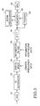
- FIG.2 shows a schematic block diagram of a conventional FFT analyzer that provides such a real time process.
- An ADC (analog to digital converter) 10 converts a signal under test into a digital signal and then an IQ separator 12 separates it into the I (In-Phase) component and the Q (Quadrature-Phase) component.
- a digital mixer 14 provides a frequency shift process to the I component data and the Q component data according to a center frequency data and a decimation filter 16 provides a decimation process to these data according to a selectable decimation coefficient.
- the decimation coefficient is defined as a ratio of the element number of the input data to that of the output data of the decimation filter 16.
- the value of the decimation coefficient data is decided depending on a setting of the data analysis span of the analyzer.
- a FFT processor 18 transforms the decimated time domain data, for example, 1024 points of the time domain data as one frame, into frequency domain data by the FFT (Fast Fourier Transform) process.
- the decimation filter 16 has a data buffer (not shown) in the output portion, a sequential storage of the one frame data, and the data are written in this data buffer sequentially and continuously.
- the FFT processor 18 can complete the FFT process of the previous frame during the storage of the new data into the data buffer that allows the real time FFT analysis of the data.
- a memory 20 stores the output data of the FFT processor 18 sequentially.
- a trigger circuit 22 can set up a trigger condition to the data in the memory 20. If the trigger condition is satisfied, the trigger circuit 22 output a trigger signal to read out the data that qualify the trigger condition from the memory 20.
- a CPU 24 controls the whole of the real time analyzer. The data read out from the memory 20 are sent to a display circuit (not shown) to display them on a display screen (not shown).
- This real time FFT analyzer can extract spectrum (or frequency component) in real time without dead time and can catch an event occurrence that meets an arbitrary trigger condition for record and display.
- What is further desired is to provide a real time signal analyzer that allows any times of resetting of the center frequency and the analysis span even if the signal has a transient variation or an incidental fluctuation.
- What is further desired is to provide a real time signal analyzer that produces time and frequency domain data at the substantial same time, having time correspondence and securing the simultaneousness between them, and can analyze them with resetting the center frequency and the analysis span.
- a real time signal analyzer has a frequency conversion means for decimating input time domain data according to a selectable decimation coefficient, a FFT processor for transforming the output data of the frequency conversion means by the FFT process in real time, a delay means for delaying the output data of the frequency conversion means for a predetermined time, a frequency domain data memory means for storing the FFT processed frequency domain data from the FFT processor, a time domain data memory means for storing the delayed time domain data read out from the delay means, and a feedback means for feeding the data read out from the time domain data memory means back to the frequency conversion means instead of said input time domain data.
- the delay means provides a predetermined delay time to the time domain data that makes the frequency domain data in the frequency domain data memory means and the time domain data in the time domain data memory means have time correspondence. It provides a repetitive FFT analysis according to the most suitable center frequency or decimation coefficient by means of feeding the time domain data from the time domain data memory means back to the frequency conversion means.
- FIG.1 shows a schematic block diagram of a preferred example embodying the present invention.
- An IQ separator 12 separates input data of time domain into I and Q components.
- a bus switch 38 selectively provides the output data of the IQ separator 12 to a digital mixer 14.
- the digital mixer 14 shifts the frequency of the time domain data according to a center frequency data.
- a decimation filter 16 decimates the frequency shifted time domain data according to a selectable decimation coefficient.
- the decimation coefficient as described above, is defined as a ratio of the element number of the input data to the element number of the output data of the decimation filter 16 for a predetermined time.
- the decimation coefficient is decided by the decimation coefficient data according to the setting of the signal analysis span and may be 1 for non-decimation.
- a clock frequency of the output data of the decimation filter changes in a wide span, for example, from 12.8MHz to 128MHz according to the change of the decimation coefficient.
- the frequency shift of the digital mixer 14 and the decimation process of the decimation filter 16 provide a frequency conversion of the time domain data and produce, for example, 1024 points of the time domain data as one frame in real time.
- This number of the data points of the one frame is just an example and would be arbitrary value according to the specification of the data display or the analysis function.
- An FFT processor 18 transforms the time domain data by the FFT process and, at the same time, multiplies it by the window function if necessary.
- the time domain data of the output data of the decimation filter 16 is also provided to a FIFO (First In First Out) memory 28.
- the FIFO memory 28 is a means for delaying the time domain data for the time corresponding to that necessary for the FFT process.
- the output data of the FFT processor 18 are the frequency domain data showing the spectrum component of the signal under test.
- the delayed time domain data output from the FIFO 28 are delayed for the FFT processing time of the FFT processor 18. Therefore the time domain data and the frequency domain data correspond in time and synchronize each other certainly. Then it is easy to compare them each other, for example, to compare and watch how the time domain data and the frequency data change in accordance with the transient variation or incidental fluctuation of the signal under test by means of displaying their waveforms on a screen at the same time.
- the first, second and third memory banks 32, 34 and 36 store the frequency domain data and the time domain data respectively provided from the FFT processor 18 and the FIFO 28 according to the setting of a bus switch 30.
- the decimation coefficient is 1, the frequency domain data output from the FFT processor 18 is stored in the first and second memory banks 32 and 34.
- Each of the first and second memory banks 32 and 34 could have a memory capacity of 1,000 frames.
- the time domain data output from the FIFO 28 is stored in the third memory bank 36 via the bus switch 30.
- the third memory bank 36 could have a memory capacity of 2,000 frames. Therefore the frequency domain data and the time domain data stored in the first, second and third memory banks could reach to a total of 2,000 frames.
- the display screen could be any display means such as a cathode-ray tube, a liquid crystal display and so on.
- a printer or a plotter etc. may be connected to output the analyzed data on paper media if necessary.
- the frequency domain data stored in the first and second memory banks 32 and 34, and the time domain data stored in the third memory bank 36 correspond in time, or are synchronized each other. Then it is easy to compare them, for example, to compare and watch how the time domain data and the frequency domain data change in accordance with the transient variation or the incidental fluctuation of the signal under test by means of displaying both waveforms on the screen at the same time.
- these of the frequency domain data and the time domain data are such a data as are acquired continuously, or without "dead time”. Therefore the data certainly reflect the transient variation and the incidental fluctuation of the signal under test.
- This invention can provide a suitable magnified display according to an arbitrary setting of the center frequency and the analysis span in low cost configuration because it recycles the time domain data stored in the third memory bank 36. If an operator changes the setting of the center frequency and the analysis span of the frequency domain for a magnified display of a portion in the first analysis display it changes the center frequency data and the decimation coefficient data according to the setting.
- the time domain data read out from the third memory bank 36 are fed back to the input of the digital mixer 14 through the bus switches 30 and 38. At this time, the bus switch 38 cut off the input data from the IQ separator 12. Therefore the digital mixer 14 shifts the frequency according to the new center frequency, and the decimation filter 16 conducts the decimation process according to the new decimation coefficient (2 or over).
- the output data of the decimation filter 16 is transformed by the FFT process to provide the frequency data for the magnified display.
- the FIFO 28 outputs the time domain data that have the time correspondence to the frequency domain data for the magnified display.
- the bus switch 30 makes the first memory bank 32 store the frequency domain data output from the FFT processor 18 and the second memory bank 34 store the time domain data output from the FIFO 28.
- This configuration rewrites and deletes the original, or the first stored frequency domain data in the first and second memory banks 32 and 34 so that if it is desired to keep the original frequency domain data, another memory may be provided to move them thereto.
- the third memory bank 36 stores the original time domain data as it is, the operator watches the frequency domain waveform displayed on the display screen (not shown), and selects another setting of the center frequency or the analysis span to produce more suitable magnified display again.
- the second memory bank 34 is used as a means for selectively storing the frequency domain data or the time domain data in the above example, different special memories may be provided for the respective data.
- the first acquired frequency and time domain data may be always kept by providing such different memories as one memory stores the first frequency and time domain data and another memory stores the frequency and time domain data newly acquired according to a new magnified setting of the center frequency and the signal analysis span.
- Each of memories may be independent or a multi-port memory may be used. As described, an engineer could choice any physical configuration or usage of the memory for the convenience.
- a real time signal analyzer that can produce time domain data and frequency domain data at the substantial same time and in real time, securing the simultaneousness between them. Besides, it can repetitively analyze the stored time domain data in various settings. Therefore it can produce the most suitable analysis data with changing the setting of the center frequency and the signal analysis span any number of times even if the signal has a transient variation or an incidental fluctuation. It could be realized at low cost in slight modified configuration without a special processor. It requires no software processing and provides hardware high-speed analysis so that it is highly useful for both analysises of the time domain data and the frequency domain data.
Landscapes
- Physics & Mathematics (AREA)
- Mathematical Physics (AREA)
- General Physics & Mathematics (AREA)
- Measuring Frequencies, Analyzing Spectra (AREA)
- Measurement Of Mechanical Vibrations Or Ultrasonic Waves (AREA)
- Complex Calculations (AREA)
Claims (10)
- Analyseur de signal en temps réel comprenant :des moyens de conversion de fréquence (14, 16) pour décimer les données d'entrée du domaine temporel selon un coefficient de décimation sélectionnable ;un processeur FFT (18) pour soumettre à un processus FFT les données de sortie des moyens de conversion de fréquence (14, 16) en temps réel ;des moyens de retard (28) pour retarder les données de sortie des moyens de conversion de fréquence pendant un temps prédéterminé ;des moyens mémoires des données du domaine fréquentiel (32, 34) pour stocker les données du domaine fréquentiel soumises à un processus FFT provenant du processeur FFT (18);des moyens mémoires des données du domaine temporel (36) pour stocker les données du domaine temporel retardées lues à partir des moyens de retard (28) ; etdes moyens de retour (30, 38) pour retransmettre les données lues à partir des moyens mémoires des données du domaine temporel (36) aux moyens de conversion de fréquence (14, 16) à la place des données d'entrée du domaine temporel.
- analyseur de signal en temps réel selon la revendication 1, dans lequel les moyens de conversion de fréquence (14, 16) déplacent la fréquence des données d'entrée du domaine temporel selon des données de fréquence centrale sélectionnables.
- Analyseur de signal en temps réel selon la revendication 1 ou 2, dans lequel les moyens de conversion de fréquence (14, 16) déciment les données du domaine temporel provenant des moyens de retour selon un coefficient de décimation qui est plus grand que le précédent.
- Analyseur de signal en temps réel selon la revendication 1, dans lequel les moyens de retard (28) établissent le temps de retard correspondant au temps de traitement du processeur FFT.
- Analyseur de signal en temps réel selon la revendication 1, dans lequel les moyens de conversion de fréquence (14, 16) sont adaptés pour déplacer la fréquence des données d'entrée du domaine temporel selon une première fréquence centrale sélectionnable et dans lequel les moyens de conversion de fréquence (14, 16) déplacent la fréquence des données du domaine temporel provenant des moyens de retour selon une seconde fréquence centrale et les déciment selon un second coefficient de décimation.
- Analyseur de signal en temps réel selon la revendication 5, dans lequel les moyens de retard (28) établissent le temps de retard correspondant au temps de traitement du processeur FFT (18).
- Analyseur de signal en temps réel selon la revendication 5 ou 6 comprenant en outre:un convertisseur analogique/numérique (10) pour convertir un signal d'entrée analogique en un signal numérique ;un séparateur IQ (12) pour produire les données d'entrée du domaine temporel en séparant le signal numérique de sortie du convertisseur analogique/numérique en des composantes I et Q.
- Analyseur de signal en temps réel selon la revendication 5, 6 ou 7, dans lequel les moyens de conversion de fréquence (14, 16) ont un mélangeur numérique (14) pour déplacer la fréquence des données d'entrée du domaine temporel selon des données de fréquence centrale sélectionnables, et un filtre de décimation (16) pour décimer les données de sortie du mélangeur numérique selon un coefficient de décimation sélectionnable.
- Analyseur de signal en temps réel selon la revendication 5, 6, 7 ou 8, dans lequel les moyens mémoires des données du domaine temporel (36) stockent les données du domaine temporel retardées dans le cas des deuxièmes données de fréquence centrale et le second coefficient de décimation indépendant de celles-ci dans le cas des premières données de fréquence centrale et du premier coefficient de décimation.
- Analyseur de signal en temps réel selon la revendication 5, dans lequel les moyens de retour (30, 38) ont des moyens de sélection pour sélectionner les données d'entrée du domaine temporel ou les données lues à partir des moyens mémoires des données du domaine temporel (36).
Applications Claiming Priority (3)
| Application Number | Priority Date | Filing Date | Title |
|---|---|---|---|
| JP4304497 | 1997-02-12 | ||
| JP04304497A JP3377391B2 (ja) | 1997-02-12 | 1997-02-12 | リアルタイム信号アナライザ |
| PCT/JP1998/000431 WO1998036284A1 (fr) | 1997-02-12 | 1998-02-02 | Analyseur de signal en temps reel |
Publications (3)
| Publication Number | Publication Date |
|---|---|
| EP0973041A1 EP0973041A1 (fr) | 2000-01-19 |
| EP0973041A4 EP0973041A4 (fr) | 2000-01-19 |
| EP0973041B1 true EP0973041B1 (fr) | 2004-08-18 |
Family
ID=12652907
Family Applications (1)
| Application Number | Title | Priority Date | Filing Date |
|---|---|---|---|
| EP98901096A Expired - Lifetime EP0973041B1 (fr) | 1997-02-12 | 1998-02-02 | Analyseur de signal en temps reel |
Country Status (5)
| Country | Link |
|---|---|
| US (1) | US6484111B1 (fr) |
| EP (1) | EP0973041B1 (fr) |
| JP (1) | JP3377391B2 (fr) |
| DE (1) | DE69825735T2 (fr) |
| WO (1) | WO1998036284A1 (fr) |
Families Citing this family (35)
| Publication number | Priority date | Publication date | Assignee | Title |
|---|---|---|---|---|
| DE60045611D1 (de) * | 1999-12-21 | 2011-03-24 | Tektronix Inc | Frequenzbereich-Analysesystem für ein Zeitbereich-Messinstrument |
| US6681191B1 (en) | 1999-12-21 | 2004-01-20 | Tektronix, Inc. | Frequency domain analysis system for a time domain measurement instrument |
| WO2002095994A1 (fr) * | 2001-05-18 | 2002-11-28 | Rohde & Schwarz Gmbh & Co. Kg | Generateur de signaux a affichage |
| US6714605B2 (en) | 2002-04-22 | 2004-03-30 | Cognio, Inc. | System and method for real-time spectrum analysis in a communication device |
| US7292656B2 (en) * | 2002-04-22 | 2007-11-06 | Cognio, Inc. | Signal pulse detection scheme for use in real-time spectrum analysis |
| US7254191B2 (en) * | 2002-04-22 | 2007-08-07 | Cognio, Inc. | System and method for real-time spectrum analysis in a radio device |
| JP4813774B2 (ja) * | 2004-05-18 | 2011-11-09 | テクトロニクス・インターナショナル・セールス・ゲーエムベーハー | 周波数分析装置の表示方法 |
| US8127242B1 (en) * | 2010-08-12 | 2012-02-28 | The United States Of America As Represented By The Secretary Of The Army | Graphic user interface and software for processing large size signal data samples in a small buffer using automatically adjusted decimation ratio |
| WO2006009955A2 (fr) * | 2004-06-23 | 2006-01-26 | Cognio, Inc | Procede, dispositif et systeme d'estimation de position a affaiblissement de propagation a etalonnage automatise |
| WO2006023575A2 (fr) * | 2004-08-19 | 2006-03-02 | Cognio, Inc. | Systeme et procede de monde surveillance et de renfort de zone sans fil reglementee |
| WO2006029071A2 (fr) * | 2004-09-03 | 2006-03-16 | Southwest Research Institute | Reacteur a plasma non thermique, a ecoulement radial, a lit fixe |
| US7765086B2 (en) * | 2004-12-09 | 2010-07-27 | Tektronix, Inc. | Modulation domain trigger |
| US7466960B2 (en) * | 2005-02-08 | 2008-12-16 | Cisco Technology, Inc. | Cognitive spectrum analysis and information display techniques |
| US20060270371A1 (en) * | 2005-05-31 | 2006-11-30 | Sugar Gary L | Tracking short-term maximum power spectrum density for improved visibility of low duty cycle signals |
| US7298129B2 (en) * | 2005-11-04 | 2007-11-20 | Tektronix, Inc. | Time arbitrary signal power statistics measurement device and method |
| US20080270440A1 (en) * | 2005-11-04 | 2008-10-30 | Tektronix, Inc. | Data Compression for Producing Spectrum Traces |
| DE102006062995B3 (de) | 2006-02-06 | 2023-06-07 | GAUSS INSTRUMENTS International GmbH | Verfahren und Anordnung zur Messung von Störemissionen in Realzeit |
| EP2016694B1 (fr) * | 2006-05-09 | 2019-03-20 | Cognio, Inc. | Système et procédé d'identification de dispositifs sans fil |
| US20080052335A1 (en) * | 2006-08-01 | 2008-02-28 | Gee Edward C | Systems and methods for time domain to frequency domain conversion using frequency shifting |
| US8233569B2 (en) * | 2006-09-28 | 2012-07-31 | Tektronix, Inc. | Realtime spectrum trigger system on realtime oscilloscope |
| JP5085105B2 (ja) * | 2006-11-24 | 2012-11-28 | テクトロニクス・インターナショナル・セールス・ゲーエムベーハー | シグナル・アナライザ |
| US8059737B2 (en) * | 2008-06-23 | 2011-11-15 | Mediatek Inc. | OFDM receiver having memory capable of acting in a single-chip mode and a diversity mode |
| US8744025B2 (en) * | 2009-08-31 | 2014-06-03 | Bae Systems Information Solutions Inc. | Digital signal conditioning |
| US20110093225A1 (en) * | 2009-10-20 | 2011-04-21 | Ramesh P E | Method of making frequency domain measurements on a time domain instrument |
| US9157943B2 (en) * | 2010-08-13 | 2015-10-13 | Tektronix, Inc. | Multi-channel frequency domain test and measurement instrument |
| US8461850B2 (en) * | 2010-08-13 | 2013-06-11 | Tektronix, Inc. | Time-domain measurements in a test and measurement instrument |
| US8521460B2 (en) * | 2010-09-28 | 2013-08-27 | Tektronix, Inc. | Multi-domain test and measurement instrument |
| US8675719B2 (en) | 2010-09-28 | 2014-03-18 | Tektronix, Inc. | Multi-domain test and measurement instrument |
| US8615382B2 (en) * | 2011-01-27 | 2013-12-24 | Tektronix, Inc. | Test and measurement instrument with common presentation of time domain data |
| KR101263388B1 (ko) | 2012-02-22 | 2013-05-21 | 자동차부품연구원 | 신호 처리 시스템 및 그 방법 |
| CA2914090C (fr) | 2015-03-31 | 2023-08-01 | Allen-Vanguard Corporation | Recepteur de diffusion en continu du domaine temporel et du domaine de frequence |
| JP6862621B2 (ja) * | 2015-12-21 | 2021-04-21 | アンリツ株式会社 | 測定装置及び測定方法 |
| DE102016000254B3 (de) * | 2016-01-12 | 2017-01-12 | Oliver Bartels | Empfänger für Spektrumanalysatoren mit erhöhter Echtzeit-Bandbreite |
| TWI689708B (zh) * | 2018-12-24 | 2020-04-01 | 財團法人工業技術研究院 | 具監測功能的振動感測器及其振動訊號監測方法 |
| US12278714B1 (en) * | 2022-10-21 | 2025-04-15 | Keysight Technologies, Inc. | RF distortion analysis and gain compression characterization based on waveform creation |
Family Cites Families (25)
| Publication number | Priority date | Publication date | Assignee | Title |
|---|---|---|---|---|
| US4471357A (en) * | 1981-10-26 | 1984-09-11 | The United States Of America As Represented By The Administrator Of The National Aeronautics And Space Administration | Pipelined digital SAR azimuth correlator using hybrid FFT/transversal filter |
| JPH0611477Y2 (ja) | 1986-04-16 | 1994-03-23 | アンリツ株式会社 | 高速フ−リエ変換アナライザ |
| US4802098A (en) * | 1987-04-03 | 1989-01-31 | Tektronix, Inc. | Digital bandpass oscilloscope |
| US5414568A (en) * | 1989-10-23 | 1995-05-09 | Matsushita Electric Industrial Co., Ltd. | Variable speed digital signal reproducing apparatus |
| US5073860A (en) * | 1989-11-07 | 1991-12-17 | Trw Vehicle Safety Systems Inc. | Method and apparatus for sensing a vehicle crash in real time using frequency domain analysis |
| WO1991015776A1 (fr) * | 1990-03-30 | 1991-10-17 | Anritsu Corporation | Dispositif d'affichage de forme d'onde pour faciliter l'observation simple d'une forme d'onde fine |
| JPH03282375A (ja) | 1990-03-30 | 1991-12-12 | Yokogawa Electric Corp | 波形表示回路 |
| JP2591864B2 (ja) * | 1991-01-30 | 1997-03-19 | 日本電気アイシーマイコンシステム株式会社 | ディジタルフィルタ |
| GB2262854B (en) * | 1991-12-24 | 1995-05-24 | Sony Broadcast & Communication | Image processing apparatus |
| US5339264A (en) * | 1992-07-27 | 1994-08-16 | Tektronix, Inc. | Symmetric transposed FIR digital filter |
| JP3728756B2 (ja) | 1992-10-13 | 2005-12-21 | 富士通株式会社 | 離散フーリエ変換値の遅延時間補正装置 |
| JPH06154222A (ja) | 1992-11-25 | 1994-06-03 | Matsushita Electric Ind Co Ltd | 超音波診断装置 |
| US5576978A (en) | 1994-05-18 | 1996-11-19 | Advantest Corporation | High resolution frequency analyzer and vector spectrum analyzer |
| JP3282375B2 (ja) | 1994-05-25 | 2002-05-13 | 株式会社デンソー | 相補型絶縁ゲート電界効果トランジスタ |
| US5696708A (en) * | 1995-03-30 | 1997-12-09 | Crystal Semiconductor | Digital filter with decimated frequency response |
| US5671168A (en) * | 1995-07-06 | 1997-09-23 | Technion Research & Development Foundation Ltd. | Digital frequency-domain implementation of arrays |
| US5757848A (en) * | 1995-11-30 | 1998-05-26 | Motorola, Inc. | Method and apparatus for a decimating digital PN correlator |
| JPH09200165A (ja) * | 1996-01-18 | 1997-07-31 | Daihen Corp | チャンネル分離用フィルタ装置、psk復調装置及びpsk受信装置 |
| US5880980A (en) * | 1996-09-30 | 1999-03-09 | Rockwell International Corporation | Distributed decimation sample rate conversion |
| US6359938B1 (en) * | 1996-10-31 | 2002-03-19 | Discovision Associates | Single chip VLSI implementation of a digital receiver employing orthogonal frequency division multiplexing |
| FI101915B (fi) * | 1996-12-04 | 1998-09-15 | Nokia Telecommunications Oy | Desimointimenetelmä ja desimointisuodatin |
| JP3359251B2 (ja) * | 1996-12-11 | 2002-12-24 | ソニー・テクトロニクス株式会社 | リアルタイム信号アナライザ |
| US5999561A (en) * | 1997-05-20 | 1999-12-07 | Sanconix, Inc. | Direct sequence spread spectrum method, computer-based product, apparatus and system tolerant to frequency reference offset |
| US5935199A (en) * | 1997-06-27 | 1999-08-10 | Cirrus Logic, Inc. | Dc accurate multi-rate digital filter with common coefficient set and dc gain correction |
| US6061705A (en) * | 1998-01-21 | 2000-05-09 | Telefonaktiebolaget Lm Ericsson | Power and area efficient fast fourier transform processor |
-
1997
- 1997-02-12 JP JP04304497A patent/JP3377391B2/ja not_active Expired - Fee Related
-
1998
- 1998-02-02 US US09/355,468 patent/US6484111B1/en not_active Expired - Fee Related
- 1998-02-02 WO PCT/JP1998/000431 patent/WO1998036284A1/fr not_active Ceased
- 1998-02-02 EP EP98901096A patent/EP0973041B1/fr not_active Expired - Lifetime
- 1998-02-02 DE DE69825735T patent/DE69825735T2/de not_active Expired - Lifetime
Also Published As
| Publication number | Publication date |
|---|---|
| WO1998036284A1 (fr) | 1998-08-20 |
| EP0973041A1 (fr) | 2000-01-19 |
| DE69825735D1 (de) | 2004-09-23 |
| JP3377391B2 (ja) | 2003-02-17 |
| JPH10227816A (ja) | 1998-08-25 |
| US6484111B1 (en) | 2002-11-19 |
| EP0973041A4 (fr) | 2000-01-19 |
| DE69825735T2 (de) | 2005-09-01 |
Similar Documents
| Publication | Publication Date | Title |
|---|---|---|
| EP0973041B1 (fr) | Analyseur de signal en temps reel | |
| EP2096451B1 (fr) | Analyseur de signaux, et procédé de génération de données pour celui-ci | |
| EP0812425B1 (fr) | Procede et machine pour l'analyse de la forme d'onde de signaux | |
| US7222055B2 (en) | High bandwidth real-time oscilloscope | |
| US7236900B2 (en) | Three dimensional correlated data display | |
| JP2733746B2 (ja) | ロジック信号表示方法 | |
| EP2434300B2 (fr) | Instrument de test et de mesure multi-domaines | |
| EP3460490B1 (fr) | Instrument de test et de mesure multi-domaines | |
| EP3508862B1 (fr) | Circuit d'analyse de signaux | |
| EP0945731B1 (fr) | Analyseur de signaux en temps reel | |
| US20040119620A1 (en) | Method and apparatus providing multiple channel multiple instrument triggering | |
| EP1960995A2 (fr) | Compression de donnees pour production d'un trace spectral | |
| CN212785392U (zh) | 一种中频信号同步处理装置及网络分析仪 | |
| EP2423691A2 (fr) | Données acquises par ré-échantillonnage pour prévenir des artéfacts d' échantillonnage cohérents | |
| Lowdermilk et al. | Cost effective, versatile, high performance, spectral analysis in a Synthetic Instrument | |
| JP2002073100A (ja) | 波形測定器の波形表示方法およびその装置 | |
| Bragg | Frontier Engineering | |
| JPH10260934A (ja) | データ取り込み回路 |
Legal Events
| Date | Code | Title | Description |
|---|---|---|---|
| PUAI | Public reference made under article 153(3) epc to a published international application that has entered the european phase |
Free format text: ORIGINAL CODE: 0009012 |
|
| 17P | Request for examination filed |
Effective date: 19990910 |
|
| A4 | Supplementary search report drawn up and despatched |
Effective date: 19991124 |
|
| AK | Designated contracting states |
Kind code of ref document: A4 Designated state(s): DE FR Kind code of ref document: A1 Designated state(s): DE FR |
|
| RAP1 | Party data changed (applicant data changed or rights of an application transferred) |
Owner name: TEKTRONIX JAPAN, LTD. |
|
| GRAP | Despatch of communication of intention to grant a patent |
Free format text: ORIGINAL CODE: EPIDOSNIGR1 |
|
| GRAS | Grant fee paid |
Free format text: ORIGINAL CODE: EPIDOSNIGR3 |
|
| GRAA | (expected) grant |
Free format text: ORIGINAL CODE: 0009210 |
|
| AK | Designated contracting states |
Kind code of ref document: B1 Designated state(s): DE FR |
|
| REF | Corresponds to: |
Ref document number: 69825735 Country of ref document: DE Date of ref document: 20040923 Kind code of ref document: P |
|
| ET | Fr: translation filed | ||
| PLBE | No opposition filed within time limit |
Free format text: ORIGINAL CODE: 0009261 |
|
| STAA | Information on the status of an ep patent application or granted ep patent |
Free format text: STATUS: NO OPPOSITION FILED WITHIN TIME LIMIT |
|
| 26N | No opposition filed |
Effective date: 20050519 |
|
| PGFP | Annual fee paid to national office [announced via postgrant information from national office to epo] |
Ref country code: FR Payment date: 20120227 Year of fee payment: 15 |
|
| PGFP | Annual fee paid to national office [announced via postgrant information from national office to epo] |
Ref country code: DE Payment date: 20120221 Year of fee payment: 15 |
|
| REG | Reference to a national code |
Ref country code: FR Ref legal event code: ST Effective date: 20131031 |
|
| REG | Reference to a national code |
Ref country code: DE Ref legal event code: R119 Ref document number: 69825735 Country of ref document: DE Effective date: 20130903 |
|
| PG25 | Lapsed in a contracting state [announced via postgrant information from national office to epo] |
Ref country code: DE Free format text: LAPSE BECAUSE OF NON-PAYMENT OF DUE FEES Effective date: 20130903 Ref country code: FR Free format text: LAPSE BECAUSE OF NON-PAYMENT OF DUE FEES Effective date: 20130228 |