EP0973061A1 - Elektromotorischer Spiegelantrieb in einer Spiegelreflexkamera - Google Patents
Elektromotorischer Spiegelantrieb in einer Spiegelreflexkamera Download PDFInfo
- Publication number
- EP0973061A1 EP0973061A1 EP99112878A EP99112878A EP0973061A1 EP 0973061 A1 EP0973061 A1 EP 0973061A1 EP 99112878 A EP99112878 A EP 99112878A EP 99112878 A EP99112878 A EP 99112878A EP 0973061 A1 EP0973061 A1 EP 0973061A1
- Authority
- EP
- European Patent Office
- Prior art keywords
- mirror
- drive
- drive arm
- viewfinder
- drive according
- Prior art date
- Legal status (The legal status is an assumption and is not a legal conclusion. Google has not performed a legal analysis and makes no representation as to the accuracy of the status listed.)
- Granted
Links
- 230000011514 reflex Effects 0.000 title claims description 3
- XEEYBQQBJWHFJM-UHFFFAOYSA-N Iron Chemical compound [Fe] XEEYBQQBJWHFJM-UHFFFAOYSA-N 0.000 claims description 12
- 238000013016 damping Methods 0.000 claims description 9
- 230000004888 barrier function Effects 0.000 claims description 7
- 229910052742 iron Inorganic materials 0.000 claims description 6
- 230000001105 regulatory effect Effects 0.000 claims description 2
- 101001017827 Mus musculus Leucine-rich repeat flightless-interacting protein 1 Proteins 0.000 description 10
- 238000010586 diagram Methods 0.000 description 3
- 230000001419 dependent effect Effects 0.000 description 1
- 238000009434 installation Methods 0.000 description 1
- 238000004091 panning Methods 0.000 description 1
Images


Classifications
-
- G—PHYSICS
- G03—PHOTOGRAPHY; CINEMATOGRAPHY; ANALOGOUS TECHNIQUES USING WAVES OTHER THAN OPTICAL WAVES; ELECTROGRAPHY; HOLOGRAPHY
- G03B—APPARATUS OR ARRANGEMENTS FOR TAKING PHOTOGRAPHS OR FOR PROJECTING OR VIEWING THEM; APPARATUS OR ARRANGEMENTS EMPLOYING ANALOGOUS TECHNIQUES USING WAVES OTHER THAN OPTICAL WAVES; ACCESSORIES THEREFOR
- G03B19/00—Cameras
- G03B19/02—Still-picture cameras
- G03B19/12—Reflex cameras with single objective and a movable reflector or a partly-transmitting mirror
-
- G—PHYSICS
- G03—PHOTOGRAPHY; CINEMATOGRAPHY; ANALOGOUS TECHNIQUES USING WAVES OTHER THAN OPTICAL WAVES; ELECTROGRAPHY; HOLOGRAPHY
- G03B—APPARATUS OR ARRANGEMENTS FOR TAKING PHOTOGRAPHS OR FOR PROJECTING OR VIEWING THEM; APPARATUS OR ARRANGEMENTS EMPLOYING ANALOGOUS TECHNIQUES USING WAVES OTHER THAN OPTICAL WAVES; ACCESSORIES THEREFOR
- G03B13/00—Viewfinders; Focusing aids for cameras; Means for focusing for cameras; Autofocus systems for cameras
- G03B13/02—Viewfinders
- G03B13/06—Viewfinders with lenses with or without reflectors
Definitions
- the invention relates to an electric motor drive for pivoting the viewfinder mirror in a single-lens reflex camera between his viewfinder and his exposure position.
- the electric drive is here as a moving coil drive trained, the magnetic head stationary within the camera housing is attached.
- To the coil form of the moving coil drive is molded onto an angular backdrop, one of which Link leg formed fork-shaped at its free end is and thereby forms a slot guide that a pin overlaps, which is parallel to the axis and with a lever distance of the pivot axis of the viewfinder mirror is attached to this.
- the invention has for its object a mirror drive to develop, which enables a position-independent pivoting.
- this object is achieved by a drive arm, which is an integral part of the electromotive
- the drive forms a fixed, parallel to the viewfinder mirror pivot axis horizontal axis of rotation reversing by electric motor pivotable and kinematically coupled to the viewfinder mirror is that the pivoting of the drive arm is opposite Pivots the viewfinder mirror.
- the kinematic connection between the drive arm and the Mirror is done in a conventional manner by a pin / Slot guide, one of which is rigidly connected to the drive arm Slot guide overlaps a pin that is parallel to the axis and with a lever distance from the pivot axis of the viewfinder mirror attached to this.
- the weight of the Drive arm applied to the mirror pin torque around the The axis of rotation of the drive arm is roughly the same size like the weight of the viewfinder mirror on his pen applied torque around the mirror pivot axis.
- the drive arm is a U-shaped, a yoke forming a magnetic soft iron yoke, the U-leg on the inside with one each Magnetic disc are fitted between the two stationary side by side arranged at the same height, flowed in the opposite direction Immerse the flat coils.
- the drive arm then the two mentioned Has flat coils that are common to one Fixed yoke between the magnetic disks are pivotable about said axis of rotation.
- one of the two pivoting end positions the magnetic arm associated with the drive arm provided that a stationary, the assigned flat coil overlapping soft iron bracket can be the one with the magnetic disk covering it includes a small air gap.
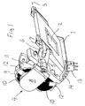
- Figure 1 shows an electric motor drive for pivoting a viewfinder mirror flap 1 with an integrated viewfinder mirror 2 a stored in a camera housing, not shown Swivel axis 3.
- the panning of the viewfinder mirror between its viewfinder and its receiving position is via a drive arm 4, the an integral part of the electric motor drive forms and around a stationary, parallel to the viewfinder mirror pivot axis 3 lying axis of rotation 5 reversing by electric motor is pivotable.
- This drive arm 4 is with the viewfinder mirror flap 1 kinematically connected via a pin / slot guide, one rigidly connected to the drive arm 4 Slot guide 6 engages over a pin 7 which is axially parallel and with a lever distance h (see e.g. Figure 3) from the Pivot axis 3 of the viewfinder mirror flap 1 attached to this is.
- the drive arm 4 is a U-shaped, a magnetic soft iron yoke forming yoke 8, the U-legs on are equipped with a magnetic disk 9 on the inside. Between these two magnetic disks 9 two immersed in a fixed position juxtaposed at the same height, facing each other current-carrying flat coils 10, the bobbins with the reference numeral 11 is provided.
- the two pivoting end positions of the drive arm 4 is in each case assigned a magnetic catch 12, which is a stationary with the Coil body 10 connected, the associated flat coil 10 overlapping Soft iron bracket is, the temple end close in the effective area the magnetic disk 9 is adjusted.
- the magnetic catch 12 secures the viewfinder mirror 2 in its viewfinder or shooting position.
- Figure 1 also allows electromagnetic damping for Detect pivoting of the viewfinder mirror flap 1.
- a stationary light barrier 13 with one on the drive arm 4 attached row of slots 14 for the light barrier signal cooperates and when pivoting the viewfinder mirror flap 1 on the mirror runtime for the current-carrying ones Flat coils 10 triggers a counter pulse that causes the pivoting the viewfinder mirror flap 1 before it stops on one dampens mirror stop 18 shown in Figure 3.
- the viewfinder mirror 1, 2 with the drive arm 4 kinematically connected to it in any position is in balance.
- This can be done in a convenient way Achieve embodiment in that the weight of the drive arm 4 torque exerted on the mirror pin 7 about the axis of rotation 5 of the drive arm 4 approximately opposite is the same size as the weight of the viewfinder mirror 1, 2 torque applied to its pin 7 about the mirror pivot axis 3rd
- FIG. 3 shows the embodiment according to FIG. 2 in a top view
- line 17 symbolizes a horizontal camera position.
- the drive arm 4 faces this horizontal line 17 a pivot angle ⁇ of z. B. 45 °.
- the one folded down Finder mirror flap 1 faces the horizontal 17 a pivot angle ⁇ of also z. B. 45 °.
- Mass torques are in equilibrium for each pivot position and thus also for that shown in Figure 4 Swivel position in which the drawn angle ⁇ each be about 5 °, which is a mirror rotation angle of 50 ° corresponds.
- Figure 5 shows diagrams for the mirror attenuation.
- the upper curve a shows the light barrier signal, with the curve end point b the End of the path, i.e. the installation of the finder mirror flap 1 at the top Specify stop 18.
- the middle curve c shows the counter impulse applied for the damping, which starts shortly before the end of the route b.
- the lower curve d shows the angle of rotation plotted over time of the mirror.
Landscapes
- Physics & Mathematics (AREA)
- General Physics & Mathematics (AREA)
- Cameras In General (AREA)
- Studio Devices (AREA)
Abstract
Description
- Figur 1
- in schaubildlicher Darstellung einen elektromotorischen Antrieb für die Verschwenkung eines Sucherspiegels;
- Figur 2
- in schematischer Darstellung die Ausführungsform gemäß Figur 1 in anderer Blickrichtung;
- Figur 3
- die Ausführungsform gemäß Figur 2 in Draufsicht bei angenommener horizontaler Kameralage;
- Figur 4
- die Darstellung gemäß Figur 3 in anderer Verschwenkstellung und
- Figur 5
- Diagramm für die Spiegeldämpfung über die Spiegellaufzeit.
Claims (10)
- Elektromotorischer Antrieb zur Verschwenkung des Sucherspiegels (1, 2) in einer einäugigen Spiegelreflexkamera zwischen seiner Sucher- und seiner Aufnahmestellung, gekennzeichnet durch einen Antriebsarm (4), der einen integralen Bestandteil des elektromotorischen Antriebes bildet, um eine ortsfeste, parallel zur Sucher-Spiegel-Schwenkachse (3) liegende Drehachse (5) elektromotorisch reversierend verschwenkbar und mit dem Sucherspiegel (1, 2) kinematisch so gekoppelt ist, daß die Verschwenkung des Antriebsarmes (4) eine gegensinnige Verschwenkung des Sucherspiegels (1, 2) hervorruft.
- Antrieb nach Anspruch 1, dadurch gekennzeichnet, daß sich der Sucherspiegel (1, 2) mit dem mit ihm kinematisch verbundenen Antriebsarm (4) lagenunabhängig im Gleichgewicht befindet.
- Antrieb nach Anspruch 1 oder 2, dadurch gekennzeichnet, daß die genannte kinematische Verbindung eine Stift/Schlitzführung (6, 7) ist, bei der eine starr mit dem Antriebsarm (4) verbundene Schlitzführung (6) einen Stift (7) übergreift, der achsparallel zu und mit einem Hebelabstand (h) von der Schwenkachse (3) des Sucherspiegels (1, 2) an diesem befestigt ist.
- Antrieb nach Anspruch 3, dadurch gekennzeichnet, daß das vom Eigengewicht des Antriebsarmes (4) auf den Spiegelstift (7) ausgeübte Drehmoment um die Drehachse (5) des Antriebsarmes (4) etwa entgegengesetzt gleichgroß ist wie das vom Eigengewicht des Sucherspiegels (1, 2) auf seinen Stift (7) ausgeübte Drehmoment um die Spiegel-Schwenkachse (3).
- Antrieb nach einem der vorhergehenden Ansprüche, dadurch gekennzeichnet, daß der Antriebsarm (4) als U-förmiges, einen Magnetweicheisen-Rückschluß bildendes Joch (8) ausgebildet ist, dessen U-Schenkel auf ihrer Innenseite mit je einer Magnetscheibe (9) bestückt sind, zwischen die zwei ortsfest nebeneinander in gleicher Höhe angeordnete, entgegengerichtet stromdurchflossene Flachspulen (10) eintauchen.
- Antrieb nach einem der vorhergehenden Ansprüche, gekennzeichnet durch eine je eine den beiden Verschwenkendstellungen des Antriebsarmes (4) zugeordnete Magnetrast (12).
- Antrieb nach Anspruch 6, dadurch gekennzeichnet, daß die Magnetrast (12) ein ortsfester, die zugeordnete Flachspule (10) übergreifender Weicheisenbügel ist, der mit der ihn überdeckenden Magnetscheibe (9) einen kleinen Luftspalt einschließt.
- Antrieb nach einem der vorhergehenden Ansprüche, gekennzeichnet durch eine elektromagnetische Dämpfung (13, 14) für die Verschwenkung des Sucherspiegels (1, 2).
- Antrieb nach Anspruch 8, dadurch gekennzeichnet, daß die Dämpfung über die Spiegellaufzeit oder über den Spiegel-Drehwinkel (b) geregelt ist.
- Antrieb nach Anspruch 9, gekennzeichnet durch eine Regelungseinrichtung, die eine ortsfeste Lichtschranke (13) aufweist, die mit einer an Antriebsarm (4) befestigten Reihe Schlitze (14) für das Lichtschrankensignal zusammen wirkt.
Applications Claiming Priority (2)
| Application Number | Priority Date | Filing Date | Title |
|---|---|---|---|
| DE19832243 | 1998-07-17 | ||
| DE19832243A DE19832243C2 (de) | 1998-07-17 | 1998-07-17 | Elektromotorischer Spiegelantrieb in einer Spiegelreflexkamera |
Publications (2)
| Publication Number | Publication Date |
|---|---|
| EP0973061A1 true EP0973061A1 (de) | 2000-01-19 |
| EP0973061B1 EP0973061B1 (de) | 2004-06-16 |
Family
ID=7874451
Family Applications (1)
| Application Number | Title | Priority Date | Filing Date |
|---|---|---|---|
| EP99112878A Expired - Lifetime EP0973061B1 (de) | 1998-07-17 | 1999-07-03 | Elektromotorischer Spiegelantrieb in einer Spiegelreflexkamera |
Country Status (6)
| Country | Link |
|---|---|
| US (1) | US6227727B1 (de) |
| EP (1) | EP0973061B1 (de) |
| JP (1) | JP2000047324A (de) |
| KR (1) | KR20000011523A (de) |
| DE (2) | DE19832243C2 (de) |
| TW (1) | TW384415B (de) |
Families Citing this family (2)
| Publication number | Priority date | Publication date | Assignee | Title |
|---|---|---|---|---|
| JP6039238B2 (ja) * | 2012-05-21 | 2016-12-07 | キヤノン株式会社 | 撮像装置 |
| KR102326702B1 (ko) | 2019-10-08 | 2021-11-16 | 엘지전자 주식회사 | 헤어 드라이어 |
Citations (5)
| Publication number | Priority date | Publication date | Assignee | Title |
|---|---|---|---|---|
| US3852791A (en) * | 1972-09-04 | 1974-12-03 | Fuji Photo Film Co Ltd | Viewfinder mirror buffer device for a single-lens reflex camera |
| US4338009A (en) * | 1981-06-08 | 1982-07-06 | Eastman Kodak Company | Bistable actuating mechanism for optical apparatus |
| US4502769A (en) * | 1982-03-11 | 1985-03-05 | Copal Company Limited | Quick-return mirror driving mechanism for single-lens reflex cameras |
| US4786929A (en) * | 1986-10-17 | 1988-11-22 | Fuji Photo Film Co., Ltd. | Single lens reflex camera |
| US5758217A (en) * | 1994-12-29 | 1998-05-26 | Rollei Fototechnic Gmba | Drive device for pivoting a mirror on a single-lens reflex camera |
Family Cites Families (6)
| Publication number | Priority date | Publication date | Assignee | Title |
|---|---|---|---|---|
| JPS535804B2 (de) * | 1972-08-15 | 1978-03-02 | ||
| US4213689A (en) * | 1979-03-22 | 1980-07-22 | Clapp Roy A | Electromagnetically actuated shutter mechanism for cameras |
| US4558938A (en) * | 1983-12-28 | 1985-12-17 | Polaroid Corporation | Twin rotatable electromagnetically driven blade mechanism |
| US4839679A (en) * | 1987-06-18 | 1989-06-13 | General Electric Corp. | Dual voice coil shutter |
| US5325142A (en) * | 1992-12-22 | 1994-06-28 | Eastman Kodak Company | Variable close loop controlled aperture/shutter system |
| JPH10148866A (ja) * | 1996-11-19 | 1998-06-02 | Asahi Optical Co Ltd | Af一眼レフカメラのプレビュー装置制御方法 |
-
1998
- 1998-07-17 DE DE19832243A patent/DE19832243C2/de not_active Expired - Fee Related
-
1999
- 1999-06-21 JP JP11174550A patent/JP2000047324A/ja active Pending
- 1999-06-25 TW TW088110725A patent/TW384415B/zh not_active IP Right Cessation
- 1999-07-03 EP EP99112878A patent/EP0973061B1/de not_active Expired - Lifetime
- 1999-07-03 DE DE59909728T patent/DE59909728D1/de not_active Expired - Fee Related
- 1999-07-06 KR KR1019990027126A patent/KR20000011523A/ko not_active Withdrawn
- 1999-07-16 US US09/354,721 patent/US6227727B1/en not_active Expired - Fee Related
Patent Citations (5)
| Publication number | Priority date | Publication date | Assignee | Title |
|---|---|---|---|---|
| US3852791A (en) * | 1972-09-04 | 1974-12-03 | Fuji Photo Film Co Ltd | Viewfinder mirror buffer device for a single-lens reflex camera |
| US4338009A (en) * | 1981-06-08 | 1982-07-06 | Eastman Kodak Company | Bistable actuating mechanism for optical apparatus |
| US4502769A (en) * | 1982-03-11 | 1985-03-05 | Copal Company Limited | Quick-return mirror driving mechanism for single-lens reflex cameras |
| US4786929A (en) * | 1986-10-17 | 1988-11-22 | Fuji Photo Film Co., Ltd. | Single lens reflex camera |
| US5758217A (en) * | 1994-12-29 | 1998-05-26 | Rollei Fototechnic Gmba | Drive device for pivoting a mirror on a single-lens reflex camera |
Also Published As
| Publication number | Publication date |
|---|---|
| JP2000047324A (ja) | 2000-02-18 |
| DE19832243A1 (de) | 2000-02-03 |
| DE19832243C2 (de) | 2002-08-14 |
| TW384415B (en) | 2000-03-11 |
| EP0973061B1 (de) | 2004-06-16 |
| DE59909728D1 (de) | 2004-07-22 |
| US6227727B1 (en) | 2001-05-08 |
| KR20000011523A (ko) | 2000-02-25 |
Similar Documents
| Publication | Publication Date | Title |
|---|---|---|
| DE3423520C2 (de) | ||
| EP0973061B1 (de) | Elektromotorischer Spiegelantrieb in einer Spiegelreflexkamera | |
| DE3911555A1 (de) | Vorrichtung zum gewichtsausgleich einer klapptuere | |
| DE4118325C2 (de) | Sucher mit variabler Brennweite | |
| DE1772900B2 (de) | Einaeugige spiegelreflexkamera mit einem spiegelbetaetigungsmechanismus | |
| DE2828943C3 (de) | Plattenspieler mit vertikal angeordneten Drehteller | |
| DE2823867B2 (de) | Zurückziehender und anhebender Spiegelantriebsmechanismus fur eine einäugige Spiegelreflexkamera | |
| DE4443336A1 (de) | Seilantrieb, insbesondere für ein Garagentor | |
| DE4224610C1 (de) | Verschwenkbare Hebelanordnung | |
| DE4230176A1 (de) | Einrichtung zum verstellen eines spiegels einer kamera | |
| DE2807271A1 (de) | Bandkassette | |
| DE2627528A1 (de) | Elektrisch leitende verbindung zwischen einer wand und einer schiebetuer | |
| DE1056262B (de) | Spannbandlagerung fuer ein Dreheisen-Messinstrument | |
| EP0922830A1 (de) | Tor, insbesondere Schnellaufrolltor | |
| DE2612050C3 (de) | Basisentfernungsmesser für eine photographische Kamera | |
| DE7518441U (de) | Antriebsvorrichtung fuer in den strahlengang eines fotografischen geraetes zu schwenkende bauteile | |
| DE841402C (de) | Filmlaufwerk | |
| DE3203577A1 (de) | Motorischer torantrieb, insbesondere fuer ein garagentor | |
| DE1236925B (de) | Einaeugige Spiegelreflexkamera | |
| DE1200127B (de) | Vorrichtung zur automatischen Filmumspulung | |
| DE1939198A1 (de) | Spiegelbetaetigungsvorrichtung einer einaeugigen reflexkamera | |
| DE1914449U (de) | Fotografische kamera mit einer belichtungssteuervorrichtung. | |
| DE9201423U1 (de) | Stellantrieb für Modelle | |
| DE1956317A1 (de) | Laufbildwerfer mit zahnrollenlosem Filmtransport | |
| DE2812097A1 (de) | Aufzugs- und antriebsvorrichtung fuer einen schlitzverschluss fuer fotografische kameras |
Legal Events
| Date | Code | Title | Description |
|---|---|---|---|
| PUAI | Public reference made under article 153(3) epc to a published international application that has entered the european phase |
Free format text: ORIGINAL CODE: 0009012 |
|
| AK | Designated contracting states |
Kind code of ref document: A1 Designated state(s): DE FR GB IT |
|
| AX | Request for extension of the european patent |
Free format text: AL;LT;LV;MK;RO;SI |
|
| 17P | Request for examination filed |
Effective date: 20000308 |
|
| AKX | Designation fees paid |
Free format text: DE FR GB IT |
|
| GRAP | Despatch of communication of intention to grant a patent |
Free format text: ORIGINAL CODE: EPIDOSNIGR1 |
|
| GRAS | Grant fee paid |
Free format text: ORIGINAL CODE: EPIDOSNIGR3 |
|
| GRAA | (expected) grant |
Free format text: ORIGINAL CODE: 0009210 |
|
| AK | Designated contracting states |
Kind code of ref document: B1 Designated state(s): DE FR GB IT |
|
| PG25 | Lapsed in a contracting state [announced via postgrant information from national office to epo] |
Ref country code: IT Free format text: LAPSE BECAUSE OF FAILURE TO SUBMIT A TRANSLATION OF THE DESCRIPTION OR TO PAY THE FEE WITHIN THE PRESCRIBED TIME-LIMIT;WARNING: LAPSES OF ITALIAN PATENTS WITH EFFECTIVE DATE BEFORE 2007 MAY HAVE OCCURRED AT ANY TIME BEFORE 2007. THE CORRECT EFFECTIVE DATE MAY BE DIFFERENT FROM THE ONE RECORDED. Effective date: 20040616 |
|
| REG | Reference to a national code |
Ref country code: GB Ref legal event code: FG4D Free format text: NOT ENGLISH |
|
| REF | Corresponds to: |
Ref document number: 59909728 Country of ref document: DE Date of ref document: 20040722 Kind code of ref document: P |
|
| GBT | Gb: translation of ep patent filed (gb section 77(6)(a)/1977) |
Effective date: 20040715 |
|
| ET | Fr: translation filed | ||
| PLBE | No opposition filed within time limit |
Free format text: ORIGINAL CODE: 0009261 |
|
| STAA | Information on the status of an ep patent application or granted ep patent |
Free format text: STATUS: NO OPPOSITION FILED WITHIN TIME LIMIT |
|
| 26N | No opposition filed |
Effective date: 20050317 |
|
| PGFP | Annual fee paid to national office [announced via postgrant information from national office to epo] |
Ref country code: DE Payment date: 20080719 Year of fee payment: 10 |
|
| PGFP | Annual fee paid to national office [announced via postgrant information from national office to epo] |
Ref country code: FR Payment date: 20080722 Year of fee payment: 10 |
|
| PGFP | Annual fee paid to national office [announced via postgrant information from national office to epo] |
Ref country code: GB Payment date: 20080723 Year of fee payment: 10 |
|
| GBPC | Gb: european patent ceased through non-payment of renewal fee |
Effective date: 20090703 |
|
| REG | Reference to a national code |
Ref country code: FR Ref legal event code: ST Effective date: 20100331 |
|
| PG25 | Lapsed in a contracting state [announced via postgrant information from national office to epo] |
Ref country code: FR Free format text: LAPSE BECAUSE OF NON-PAYMENT OF DUE FEES Effective date: 20090731 |
|
| PG25 | Lapsed in a contracting state [announced via postgrant information from national office to epo] |
Ref country code: GB Free format text: LAPSE BECAUSE OF NON-PAYMENT OF DUE FEES Effective date: 20090703 |
|
| PG25 | Lapsed in a contracting state [announced via postgrant information from national office to epo] |
Ref country code: DE Free format text: LAPSE BECAUSE OF NON-PAYMENT OF DUE FEES Effective date: 20100202 |