EP0973073B1 - Appareil de formation d'images - Google Patents
Appareil de formation d'images Download PDFInfo
- Publication number
- EP0973073B1 EP0973073B1 EP99305459A EP99305459A EP0973073B1 EP 0973073 B1 EP0973073 B1 EP 0973073B1 EP 99305459 A EP99305459 A EP 99305459A EP 99305459 A EP99305459 A EP 99305459A EP 0973073 B1 EP0973073 B1 EP 0973073B1
- Authority
- EP
- European Patent Office
- Prior art keywords
- image
- cleaning
- forming apparatus
- bias
- cleaning bias
- Prior art date
- Legal status (The legal status is an assumption and is not a legal conclusion. Google has not performed a legal analysis and makes no representation as to the accuracy of the status listed.)
- Expired - Lifetime
Links
- 238000004140 cleaning Methods 0.000 claims description 92
- 230000000694 effects Effects 0.000 claims description 7
- 230000015572 biosynthetic process Effects 0.000 claims description 4
- 238000000034 method Methods 0.000 description 12
- 239000000463 material Substances 0.000 description 9
- 230000005611 electricity Effects 0.000 description 6
- 238000010276 construction Methods 0.000 description 5
- 229920001971 elastomer Polymers 0.000 description 4
- 239000000523 sample Substances 0.000 description 4
- 239000011248 coating agent Substances 0.000 description 3
- 238000000576 coating method Methods 0.000 description 3
- 229920002943 EPDM rubber Polymers 0.000 description 2
- 238000009825 accumulation Methods 0.000 description 2
- 230000003247 decreasing effect Effects 0.000 description 2
- 238000009413 insulation Methods 0.000 description 2
- 238000007639 printing Methods 0.000 description 2
- 238000000926 separation method Methods 0.000 description 2
- 230000004075 alteration Effects 0.000 description 1
- AZDRQVAHHNSJOQ-UHFFFAOYSA-N alumane Chemical group [AlH3] AZDRQVAHHNSJOQ-UHFFFAOYSA-N 0.000 description 1
- XAGFODPZIPBFFR-UHFFFAOYSA-N aluminium Chemical compound [Al] XAGFODPZIPBFFR-UHFFFAOYSA-N 0.000 description 1
- 229910052782 aluminium Inorganic materials 0.000 description 1
- 230000015556 catabolic process Effects 0.000 description 1
- 238000011109 contamination Methods 0.000 description 1
- 238000006731 degradation reaction Methods 0.000 description 1
- 229910052736 halogen Inorganic materials 0.000 description 1
- 150000002367 halogens Chemical class 0.000 description 1
- 238000010438 heat treatment Methods 0.000 description 1
- 239000002245 particle Substances 0.000 description 1
- 230000002093 peripheral effect Effects 0.000 description 1
- 239000011347 resin Substances 0.000 description 1
- 229920005989 resin Polymers 0.000 description 1
- 230000004044 response Effects 0.000 description 1
- 238000007790 scraping Methods 0.000 description 1
- 238000005507 spraying Methods 0.000 description 1
- 230000000087 stabilizing effect Effects 0.000 description 1
- 230000001360 synchronised effect Effects 0.000 description 1
- 238000011144 upstream manufacturing Methods 0.000 description 1
- 239000002699 waste material Substances 0.000 description 1
Images



Classifications
-
- G—PHYSICS
- G03—PHOTOGRAPHY; CINEMATOGRAPHY; ANALOGOUS TECHNIQUES USING WAVES OTHER THAN OPTICAL WAVES; ELECTROGRAPHY; HOLOGRAPHY
- G03G—ELECTROGRAPHY; ELECTROPHOTOGRAPHY; MAGNETOGRAPHY
- G03G15/00—Apparatus for electrographic processes using a charge pattern
- G03G15/14—Apparatus for electrographic processes using a charge pattern for transferring a pattern to a second base
- G03G15/16—Apparatus for electrographic processes using a charge pattern for transferring a pattern to a second base of a toner pattern, e.g. a powder pattern, e.g. magnetic transfer
- G03G15/1665—Apparatus for electrographic processes using a charge pattern for transferring a pattern to a second base of a toner pattern, e.g. a powder pattern, e.g. magnetic transfer by introducing the second base in the nip formed by the recording member and at least one transfer member, e.g. in combination with bias or heat
- G03G15/167—Apparatus for electrographic processes using a charge pattern for transferring a pattern to a second base of a toner pattern, e.g. a powder pattern, e.g. magnetic transfer by introducing the second base in the nip formed by the recording member and at least one transfer member, e.g. in combination with bias or heat at least one of the recording member or the transfer member being rotatable during the transfer
- G03G15/168—Apparatus for electrographic processes using a charge pattern for transferring a pattern to a second base of a toner pattern, e.g. a powder pattern, e.g. magnetic transfer by introducing the second base in the nip formed by the recording member and at least one transfer member, e.g. in combination with bias or heat at least one of the recording member or the transfer member being rotatable during the transfer with means for conditioning the transfer element, e.g. cleaning
-
- G—PHYSICS
- G03—PHOTOGRAPHY; CINEMATOGRAPHY; ANALOGOUS TECHNIQUES USING WAVES OTHER THAN OPTICAL WAVES; ELECTROGRAPHY; HOLOGRAPHY
- G03G—ELECTROGRAPHY; ELECTROPHOTOGRAPHY; MAGNETOGRAPHY
- G03G2215/00—Apparatus for electrophotographic processes
- G03G2215/02—Arrangements for laying down a uniform charge
- G03G2215/021—Arrangements for laying down a uniform charge by contact, friction or induction
-
- G—PHYSICS
- G03—PHOTOGRAPHY; CINEMATOGRAPHY; ANALOGOUS TECHNIQUES USING WAVES OTHER THAN OPTICAL WAVES; ELECTROGRAPHY; HOLOGRAPHY
- G03G—ELECTROGRAPHY; ELECTROPHOTOGRAPHY; MAGNETOGRAPHY
- G03G2215/00—Apparatus for electrophotographic processes
- G03G2215/16—Transferring device, details
- G03G2215/1647—Cleaning of transfer member
- G03G2215/1652—Cleaning of transfer member of transfer roll
Definitions
- the present invention relates to an image forming apparatus of electrophotographic or electrostatic type such as a copying machine, a printer and the like, and more particularly, it relates to an image forming apparatus having a transfer portion urged against an image bearing member.
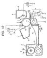
- Fig. 12 shows an example of an electrophotographic image forming apparatus.
- the image forming apparatus utilizes a transfer roller 11 urged against a photosensitive drum 1 as a transfer member for transferring a toner image formed on the photosensitive drum 1 onto a transfer material P.
- toner is adhered to a surface of the transfer roller 11, smears on a back surface of the sheet will be generated. It is preferable that, when the sheet is not passed through the transfer roller, cleaning bias having polarity opposite to that of the toner adhered to the transfer roller is applied to transfer the toner back onto the photosensitive drum 1, and the transferred toner is collected by a cleaning device 5.
- Fig. 10 is a sequence chart showing a relationship between surface potential of the photosensitive drum 1 (photosensitive drum potential) in the above-mentioned image forming apparatus, developing bias, transfer bias and cleaning bias.
- a relationship between the surface potential of the photosensitive drum 1, the developing bias of a developing device 3 and the transfer bias of a transfer device 4 is shown by using a circumferential position of the photosensitive drum 1 as a reference.
- the photosensitive drum 1 is uniformly charged with dark potential V D of -650V by a charge roller 6, and the uniformly charged portion is exposed in accordance with image information to form an electrostatic latent image.
- the dark potential V D of the surface is maintained to -650V by the charge roller 6 from when pre-rotation in which the charged position reaches a transfer nip portion N is effected in synchronism with a timing for reaching the transfer material P to the transfer nip portion N to when the charged position reaches the transfer nip portion N in synchronism with a timing for passing a trailing end of a final transfer sheet P through the transfer nip portion N.
- bright potential V L of an image portion of the electrostatic latent image formed by exposure light L becomes -200V.
- DC voltage developing bias of -500V is applied from a developing bias applying power source 10 to a developing roller 9 from when pre-rotation in which the electrostatic latent image on the photosensitive drum 1 is developed and is reached to the transfer nip portion N is effected in synchronism with a timing for reaching the transfer material P to the transfer nip portion N to when a toner image reaches the transfer nip portion N in synchronism with a timing for passing the final transfer sheet P through the transfer nip portion N.
- the cleaning bias of -1500V is applied from a transfer roller cleaning bias applying power source 23 to the transfer roller 11 when the surface potential of the photosensitive drum 1 is zero in the pre-rotation and post-rotation.
- transfer bias V T is applied to the transfer roller, and, between the sheets (i.e., in a sheet interval), bias voltage V TO smaller than the transfer bias is applied to the transfer roller.
- the transfer bias V T is voltage for reserving transfer current required during the passing of the sheet and is varied in accordance with resistance of the transfer roller 11.
- voltage capable of reserving current of about 10 ⁇ A is applied to the transfer roller.
- the bias voltage V TO is made smaller in order to prevent transfer memory to the photosensitive drum 1.
- the toner adhered to the transfer roller 11 as the smears includes not only the properly charged toner but also toner charged oppositely within the developing device 3 and/or toner which was properly charged and which was then charged with opposite polarity by discharge action generated during the application of the cleaning bias.
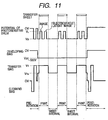
- negative toner and positive toner are adhered to the transfer roller 11 in this way, as shown in Fig. 11, in pre-rotation and post-rotation, negative bias and positive bias might be applied to the transfer roller 11 as the cleaning bias.
- memory may be generated on the photosensitive drum 1 due to the cleaning bias to affect a bad influence upon next image formation.
- the influence of the memory can be prevented by removing AC electricity from the photosensitive drum 1 (charged by the cleaning bias) by means of a charger 2.
- JP-A-6-51654 describes cleaning of a transfer member after a preset number of sheets have been printed.
- An object of the present invention is to provide an image forming apparatus which can reduce or prevent smears of a transfer roller.
- Another object of the present invention is to provide an image forming apparatus which can reduce or prevent potential memory on a photosensitive member.
- a further object of the present invention is to provide an image forming apparatus in which a service life of the photosensitive member is not shortened.
- a still further object of the present invention is to provide an image forming apparatus comprising an image bearing member for bearing a toner image, a transfer member for electrostatically transferring the toner image or the image bearing member, a cleaning bias applying means for electrostatically cleaning the transfer member by applying cleaning bias to the transfer member, and a control means for controlling application of the cleaning bias in accordance with the number of sheets to be image-formed in one image forming job.
- Fig. 1 is a sectional view of an image forming apparatus according to a first embodiment of the present invention.
- the image forming apparatus shown in Fig. 1 includes a photosensitive member as an image bearing member.
- the photosensitive member is a rotary drum-shaped electrophotographic photosensitive member (referred to as "photosensitive drum” hereinafter) 1 constituted by coating an organic photosensitive body (OPC) photosensitive layer on a surface of an aluminum cylinder.
- the photosensitive drum 1 preferably has an outer diameter of 30 mm and is rotated at a process speed (peripheral speed) of 150 mm/sec.
- a charging device 2 for uniformly charging the photosensitive drum 1
- an exposure device (not shown) for emitting exposure light (laser light) L to form an electrostatic latent image on the photosensitive drum 1
- a developing device 3 for forming (visualizing) a toner image by adhering toner to the electrostatic latent image formed on the photosensitive drum 1
- a transfer device 4 for transferring the toner image formed on the photosensitive drum 1 onto a transfer sheet P such as a paper sheet
- a cleaning device 5 for cleaning the surface of the photosensitive drum 1.
- the charging device 2 includes a charge roller 6 as a contact charging member, and a charging bias applying power source 7 for applying charging bias to the charge roller 6.
- the developing device 3 includes a developing container 8 for storing toner as developer, a developing roller (developing member) 9 for visualizing the electrostatic latent image formed on the photosensitive drum 1 by transferring the toner to the drum, and a developing bias applying power source 10 for applying developing bias to the developing roller 9.
- the transfer device 4 includes a transfer roller (contact transfer member) preferably having an outer diameter of 20 mm, a transfer bias applying power source 12 for applying transfer bias of about 1000 to 6000 V to the transfer roller 11, a transfer roller cleaning bias applying power source 23 for applying transfer roller cleaning bias to the transfer roller 11 in non-passing of sheet, and a switch 39 for selecting either the transfer bias applying power source 12 or the transfer roller cleaning bias applying power source 23 to apply the bias to the transfer roller 11.
- the transfer roller 11 is constituted by coating a conductive elastic layer 11b on a metallic core cylinder 11a, and the elastic layer 11b has a resistance value of about 10 6 to 10 10 ⁇ •cm.
- the cleaning device 5 includes a cleaning blade 13 for scraping toner (transfer residual toner) remaining on the surface of the photosensitive drum which was not transferred to the transfer material, and a collecting container 14 for storing the transfer residual toner scraped by the cleaning blade 13 as waste toner.
- the transfer sheet P to which the toner image was transferred is separated from the photosensitive drum 1 due to small diameter of the photosensitive drum, and electricity on the transfer sheet is removed by an electricity removing probe unit (separation aiding means) 15. As a result, an electrostatic attraction force between the transfer sheet P and the photosensitive drum 1 is weakened, thereby separating the transfer sheet from the photosensitive drum 1.
- the electricity removing probe unit 15 includes an electricity removing probe 15a and an insulation member 15b, and the electricity removing probe 15a is electrically grounded.
- the transfer sheet P is guided on a convey guide made of insulation resin to be conveyed to a fixing device 17.
- the fixing device 17 includes a fixing roller 18 (having a PFA mold releasing layer 18b obtained by spray-coating or dispersion-coating PFA particles on a cylindrical aluminum core 18a and then by baking PFA), a halogen heater for heating the fixing roller internally, a pressure roller 20 for urging the transfer sheet P against the fixing roller 18, and a fixing inlet guide 21 for directing the transfer sheet P into a fixing nip portion between the fixing roller 18 and the pressure roller 20. While the transfer sheet P bearing a non-fixed toner image is being passed through the fixing nip portion, the toner image is melted and fixed to the surface of the transfer sheet P.
- a fixing roller 18 having a PFA mold releasing layer 18b obtained by spray-coating or dispersion-coating PFA particles on a cylindrical aluminum core 18a and then by baking PFA
- a halogen heater for heating the fixing roller internally
- a pressure roller 20 for urging the transfer sheet P against the fixing roller 18
- a fixing inlet guide 21 for
- the photosensitive drum 1 is uniformly charged with negative dark potential V D of about -650V by applying the charging bias from the charging bias applying power source 7 to the charge roller 6 and then is image-exposed by the exposure light L, thereby forming the electrostatic latent image in which the exposed portion has bright potential V L .
- the potential V L is about -200V.
- the electrostatic latent image formed on the photosensitive drum 1 is developed by the developing device 3. That is to say, the electrostatic latent image formed on the photosensitive drum 1 is developed (visualized) as the toner image by transferring the negatively charged toner on the developing roller 9 onto the bright potential V L portion on the photosensitive drum 1 by applying the developing bias from the developing bias applying power source 10 to the developing roller 9.
- the toner image formed on the photosensitive drum 1 is transferred onto the transfer sheet P conveyed along a transfer guide 22, in a transfer nip portion N between the photosensitive drum 1 and the transfer roller 11.
- the toner adhered to the transfer roller 11 as smears during the transferring is transferred onto the photosensitive drum 1 by applying bias having the same polarity as the charging polarity of the toner from the transfer roller cleaning bias applying power source 23 to the transfer roller 11 in pre-rotation and post-rotation (non-passing of sheet), and the transferred toner is collected by the cleaning device 5, thereby cleaning the surface of the photosensitive drum 1.
- the above-mentioned image forming apparatus according to the first embodiment of the present invention shown in Fig. 1 further includes a printer engine 41 having an engine control portion 40 and a formatter 42, which formatter 42 is connected to an external device 43 such as a personal computer.
- an image signal and a sheet number signal from the external device 43 are transmitted to the formatter 42 of the image forming apparatus (referred to as "printer” hereinafter), where the image signal is converted into an ON/OFF signal for the exposure device.
- the engine control portion 40 receives a signal from the formatter 42 and effects engine control for the print while communicating with the formatter 42.
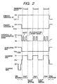
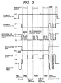
- the application of the charging bias and the application of the transfer roller cleaning bias are effected as shown in Figs. 2 and 3.
- Fig. 2 shows a sequence chart when the number of sheets is small (for example, 1 to 19 sheets).
- the primary charging AC bias is turned OFF.
- a time period for applying the primary charging AC bias is shortened to reduce degradation of the OPC layer due to discharge, thereby improving the service life of the photosensitive drum 1.
- pre-rotation means a step for effecting pre-process of the photosensitive member from when the print command is inputted to when the print is started
- post-rotation means a step for effecting post-process of the photosensitive member after the print is finished.
- Fig. 3 shows sequence chart when the number of sheets is great (continuous print for twenty or more sheets).
- the cleaning of the transfer roller is effected in the post-rotation.
- the primary charging DC bias is changed to 0 Volt at a circumferential position on the photosensitive drum 1 in synchronism with the changing the transfer bias to the cleaning bias.
- this is assumed as a zone A, it is preferable that the zone A is greater than one circumference of the transfer roller 11 and is equal to an integral number of times the time period required for one revolution of the transfer roller 11.
- the bias of the transfer roller is set to the transfer bias V T .
- the primary charging DC bias of the charge roller 6 is set to V D converging bias V CDC and the potential of the photosensitive drum is set to V D .
- the value V CDC is generally set to a value obtained by adding about 10 to 30 V to the V D potential of the photosensitive drum 1.
- V D of -650V when the positive bias is applied to the transfer roller 11 is to prevent so-called transfer memory tending to charge the photosensitive drum 1 by the transfer bias.
- a zone in which the transfer bias V T is applied to the transfer roller 11 is "B", similar to the zone A, it is preferable that the zone B is also greater than one circumference of the transfer roller 11 and is equal to an integral number of times the time period required for one revolution of the transfer roller 11. The reason is that the entire circumference of the transfer roller 11 can be cleaned uniformly.
- the cleaning bias is applied to the transfer roller 11 alternately, starting from the negative bias (then positive bias).
- the negative bias is applied to clean the negatively charged toner, although most toner is returned to the photosensitive drum 1, since a small part of toner remains on the transfer roller 11 and the residual toner is charged positively due to discharge of the transfer roller 11 and the photosensitive drum 1, the positive bias is required to be then applied to remove the residual toner. If the positive bias is firstly applied, initial great cleaning effect cannot be achieved. Namely, if the cleaning bias is applied to the transfer roller alternately, starting from the positive bias, longer cleaning time is required in comparison with the case starting from the negative bias, which affects a bad influence upon the service life of the photosensitive drum 1.
- the primary DC charging bias is converged to 0 Volt
- the surface potential of the photosensitive drum 1 is converged to 0 Volt by turning-ON the primary charging AC bias. The reason is to remove the memory of the photosensitive drum due to execution of the great number of prints and application of positive bias for cleaning.
- the material of the elastic layer 11b of the transfer roller 11 of the printer engine 41 is polar rubber such as NBR. Unlike to non-polar rubber such as EPDM, since the polar rubber has a property capable adhering toner easily, the cleaning using the negative bias and positive bias is inevitable. If the elastic layer 11b is made of non-polar rubber such as EPDM, since an amount of the toner adhered is small and the toner is apt to be separated, only the negative bias may be applied.
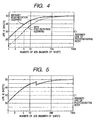
- Fig. 4 is a graph showing a relationship between the number of prints in one job (referred to as "number of jobs” hereinafter) and the service life of the photosensitive drum 1.
- “one job” means prints or copies effected in response to operator's one print or copy command.
- "K sheets” in the ordinate is 1000 sheets.
- a solid line curve indicates the result when the cleaning was not effected in the post-rotation, and the broken line curve indicates the result when the cleaning was effected in the post-rotation.
- the reason why the greater the number of jobs in one print the longer the service life is that a ratio of the time period for applying the cleaning bias in the post-rotation cleaning to the total time period for applying the primary charging AC bias becomes small.
- the life is generally calculated on the basis of 2 job number (number of jobs) (two-sheets intermittent).
- the service life of the photosensitive drum 1 in the graph was based upon a case where 30000 sheets (30 K sheets) is effected by the two-sheets intermittent. As shown in Fig. 4, when the cleaning was effected in the post-rotation, in the two-sheets intermittent, the service life of the photosensitive drum 1 is merely 20000 sheets (20 K sheets). In order to obtain the service life of 30000 sheets, the number of jobs must be 5 or more.
- the service life of the photosensitive drum 1 was extended.
- the number of jobs with the post-rotation cleaning is selected to 5 or more, the life substantially the same as the life of 2 job number without the post-rotation cleaning can be achieved.
- the reason why the post-rotation cleaning is effected in case of 20 or more job number is that the life is desired to be extended as long as possible when the number of jobs is great and that, since accumulation of smears on the transfer roller 11 had a level causing no problem regarding the image up to 100 job number, 20 job number is selected with leaving a margin.
- Fig. 5 shows a relationship between the number of jobs and the service life of the photosensitive drum 1. From Fig. 5, it will be found that the relationship between the number of jobs and the life is 30000 sheets in case of 2 job number, which is the same as the conventional case. Between 19 job number and 20 job number, although the life is decreased from 47000 sheets to 43000 sheets, since 43000 sheets are greater than 30000 sheets (designed life), there is no practical problem.
- the transfer roller 11 can be cleaned by using the pre-rotation cleaning bias in the next print process and by transferring the accumulated toner onto back surfaces of the transfer sheets P during the print.
- smears of the back surface of the transfer sheet P is very little and a level of the image (smears of the back surface) does not cause any problem.
- the cleaning process of the transfer roller 11 may be effected not only in the post-rotation but also in the pre-rotation or after all of the printing operations are finished and after rotation of a motor is stopped.
- Fig. 6 shows a sequence chart according to the second embodiment.
- the post-rotation cleaning time period is changed in accordance with the number of jobs so that the cleaning time period is lengthened when the number of prints in one job is great.
- the combination of the zones A and B for the post-rotation cleaning bias is effected by two times when the print number is from 5 to 7 both inclusive, by three times when the print number is from 8 to 12 both inclusive and by four times when the print number is from 13 to 18 both inclusive, and so on (i.e., increased in accordance with the number of jobs).
- the time period D for effecting the post-rotation cleaning is lengthened as the number of jobs is increased. In this way, if the contamination toner is apt to be accumulated due to the large number of jobs, the cleaning ability is improved.
- the service life of the photosensitive drum 1 in this case is shown in Fig. 7. Since the cleaning time period is lengthened when the number of jobs is great, the service life of the photosensitive drum 1 is not lengthened by increasing the number of jobs. However, since the service life is not decreased below the designed life, there is no practical problem.
- an image having no smears of back surface can be formed. Accordingly, degrees of freedom for apparatus design or material selection can be increased.
- the cleaning process of the transfer roller 11 may be effected not only in the post-rotation but also in the pre-rotation or after all of the printing operations are finished and after rotation of a motor is stopped.
- Fig. 8 shows a schematic construction of an alternative image forming apparatus.
- the same elements as those in the first embodiment shown in Fig. 1 are designated by the same reference numerals, and explanation thereof will be omitted.
- the image forming apparatus shown in Fig. 8 comprises a printer engine 41, a sheet feeding cassette (transfer material containing means) 44 capable of containing 500 sheets, and a deck (transfer material containing means) 45 capable of containing 2000 sheets.
- a cassette intermediate plate 46 disposed within the sheet feeding cassette 44 and adapted to lift transfer sheets P and a similar deck intermediate plate 47 disposed within the deck 45 are driven by a main motor (not shown) of the printer engine 41 in replenishment of sheets.
- the photosensitive drum 1 is rotated.
- Such an arrangement is general in middle-size and small-size image forming apparatuses.
- Fig. 9 is a sequence chart showing such cleaning.
- the cleaning sequence for the transfer roller 11 is performed together with rotation for the lift-up.
- explanation of process will be omitted since the process is the same as the post-rotation sequence in the first embodiment, after the combination of the zones A and B for cleaning the transfer roller 11 is effected by two times and the zone C for stabilizing the potential of the photosensitive drum 1 is effected by one time, all of the biases are turned OFF, and the main motor is rotated until the lift-up is finished. As a result, the cleaning of the transfer roller 11 can be effected even during the lift-up.
- the cleaning sequence is effected only in the replenishment of transfer sheets P regarding the sheet feeding cassette 44 or the deck 45, i.e., effected every 500 sheets or 2000 sheets.
- the service life of the photosensitive drum 1 is almost not influenced.
Landscapes
- Physics & Mathematics (AREA)
- General Physics & Mathematics (AREA)
- Electrostatic Charge, Transfer And Separation In Electrography (AREA)
- Control Or Security For Electrophotography (AREA)
- Cleaning In Electrography (AREA)
Claims (10)
- Appareil de formation d'images comportant :un corps porteur d'image (1) destiné à porter une image en toner ;un élément de report (11) destiné à reporter électrostatiquement l'image en toner se trouvant sur ledit corps porteur d'image, ledit appareil étant conçu pour effectuer la formation d'une image sur une pluralité de feuilles dans une tâche de formation d'image ;un moyen (23, 39) d'application d'une polarisation de nettoyage destiné à nettoyer électrostatiquement ledit élément de report (11) en appliquant une polarisation de nettoyage audit élément de report, ledit moyen d'application de polarisation de nettoyage étant conçu pour appliquer la polarisation de nettoyage audit élément de report après l'achèvement de la tâche de formation d'image ;caractérisé en ce qu'il comporte en outre :un moyen de commande (40) destiné à commander l'application de la polarisation de nettoyage après la finition de la tâche de formation d'image, en fonction du nombre de feuilles sur lesquelles une image doit être formée dans une tâche de formation d'image.
- Appareil de formation d'images selon la revendication 1, dans lequel ledit moyen de commande (40) commande l'application de la polarisation de nettoyage d'une manière telle que le nettoyage est effectué lorsque le nombre de feuilles sur lesquelles une image doit être formée est supérieur ou égal à une valeur prédéterminée, et le nettoyage n'est pas effectué lorsque le nombre de feuilles sur lesquelles une image doit être formée est inférieur à la valeur prédéterminée.
- Appareil de formation d'images selon la revendication 1 ou la revendication 2, dans lequel ledit moyen de commande (40) règle une période de temps pour l'application de la polarisation de nettoyage.
- Appareil de formation d'images selon la revendication 3, dans lequel ledit moyen de commande (40) peut être mis en oeuvre pour régler la période de temps d'une manière telle que la période de temps pour l'application de la polarisation de nettoyage est augmentée lorsque le nombre de feuilles sur lesquelles une image doit être formée est supérieur ou égal à une valeur prédéterminée.
- Appareil de formation d'images selon l'une quelconque des revendications précédentes, dans lequel ledit moyen (23, 29) d'application de polarisation de nettoyage applique aussi la polarisation de nettoyage audit élément de report avant le commencement de la tâche de formation d'image.
- Appareil de formation d'images selon la revendication 5, dans lequel un état d'application de polarisation de nettoyage avant le commencement de la tâche de formation d'image est constant indépendamment du nombre de feuilles sur lesquelles une image doit être formée.
- Appareil de formation d'images selon la revendication 1, dans lequel ledit moyen d'application de polarisation de nettoyage applique une polarisation de nettoyage ayant la même polarisation que celle d'un toner et une polarisation de nettoyage ayant une polarisation opposée à celle du toner audit élément de report.
- Appareil de formation d'images selon la revendication 1, dans lequel ledit élément de report (11) a la forme d'un rouleau et coopère avec ledit corps porteur d'image pour qu'une zone de pincement soit formée entre eux.
- Appareil de formation d'images selon la revendication 1, comportant en outre un élément de charge (6) destiné à charger uniformément ledit corps porteur d'image (1) et une source (7) d'énergie à courant alternatif destinée à appliquer une tension alternative audit élément de charge, dans lequel une partie de la surface dudit corps porteur d'image placée dans une position de report pendant l'application de la polarisation de nettoyage est soumise à une élimination des charges électrostatiques par ledit élément de charge.
- Appareil de formation d'images selon la revendication 9, comportant en outre une source d'énergie à courant continu destinée à appliquer une tension continue audit élément de charge, dans lequel la tension continue et la tension alternative sont appliquées audit élément de charge de façon superposée pendant la formation d'une image.
Applications Claiming Priority (2)
| Application Number | Priority Date | Filing Date | Title |
|---|---|---|---|
| JP19785998 | 1998-07-13 | ||
| JP19785998A JP3279523B2 (ja) | 1998-07-13 | 1998-07-13 | 画像形成装置 |
Publications (3)
| Publication Number | Publication Date |
|---|---|
| EP0973073A2 EP0973073A2 (fr) | 2000-01-19 |
| EP0973073A3 EP0973073A3 (fr) | 2001-04-04 |
| EP0973073B1 true EP0973073B1 (fr) | 2005-09-21 |
Family
ID=16381527
Family Applications (1)
| Application Number | Title | Priority Date | Filing Date |
|---|---|---|---|
| EP99305459A Expired - Lifetime EP0973073B1 (fr) | 1998-07-13 | 1999-07-09 | Appareil de formation d'images |
Country Status (4)
| Country | Link |
|---|---|
| US (1) | US6173135B1 (fr) |
| EP (1) | EP0973073B1 (fr) |
| JP (1) | JP3279523B2 (fr) |
| DE (1) | DE69927324T2 (fr) |
Families Citing this family (36)
| Publication number | Priority date | Publication date | Assignee | Title |
|---|---|---|---|---|
| JP2002049232A (ja) | 2000-08-07 | 2002-02-15 | Canon Inc | 画像形成装置およびプロセスカートリッジ |
| JP4603672B2 (ja) * | 2000-10-20 | 2010-12-22 | キヤノン株式会社 | 画像形成装置 |
| JP2002287598A (ja) * | 2001-03-28 | 2002-10-03 | Brother Ind Ltd | 画像形成装置 |
| JP4928023B2 (ja) * | 2001-04-27 | 2012-05-09 | キヤノン株式会社 | 画像形成装置 |
| JP4154168B2 (ja) * | 2002-04-15 | 2008-09-24 | キヤノン株式会社 | 画像形成装置 |
| JP4073262B2 (ja) * | 2002-06-26 | 2008-04-09 | シャープ株式会社 | 転写部材クリーニング方法及び画像形成装置 |
| JP2004117509A (ja) * | 2002-09-24 | 2004-04-15 | Canon Inc | 画像形成装置 |
| JP4464092B2 (ja) * | 2002-09-30 | 2010-05-19 | キヤノン株式会社 | 画像形成装置 |
| JP3870204B2 (ja) | 2004-06-09 | 2007-01-17 | キヤノン株式会社 | 画像形成装置 |
| US7242887B2 (en) * | 2004-06-17 | 2007-07-10 | Canon Kabushiki Kaisha | Image forming apparatus which can optimize cleaning time of transfer member contacting inter-image area of image bearing member |
| JP4817722B2 (ja) * | 2004-06-17 | 2011-11-16 | キヤノン株式会社 | 画像形成装置 |
| JP4250581B2 (ja) * | 2004-09-29 | 2009-04-08 | キヤノン株式会社 | 画像形成装置 |
| JP5214093B2 (ja) * | 2005-01-31 | 2013-06-19 | 京セラドキュメントソリューションズ株式会社 | 画像形成装置 |
| US7496306B2 (en) * | 2006-03-03 | 2009-02-24 | Kabushiki Kaisha Toshiba | Cleaning method for transfer device of image forming apparatus |
| KR101299447B1 (ko) * | 2006-12-20 | 2013-08-22 | 삼성전자주식회사 | 화상형성장치 및 그 잔류토너 제거방법 |
| US20090052921A1 (en) * | 2007-08-22 | 2009-02-26 | Kabushiki Kaisha Toshiba | Image forming apparatus, cleaning method and cleaning program |
| JP5257760B2 (ja) * | 2008-07-18 | 2013-08-07 | 株式会社リコー | 転写装置及びこれを用いた画像形成装置 |
| EP2144123B1 (fr) | 2008-07-08 | 2016-10-19 | Ricoh Company, Ltd. | Unité de transfert et appareil de formation d'images utilisant l'unité de transfert |
| JP2012098403A (ja) * | 2010-10-29 | 2012-05-24 | Kyocera Mita Corp | 画像形成装置 |
| JP5573634B2 (ja) * | 2010-11-26 | 2014-08-20 | コニカミノルタ株式会社 | 画像形成装置 |
| JP2012123251A (ja) | 2010-12-09 | 2012-06-28 | Canon Inc | 画像形成装置 |
| JP2013114210A (ja) | 2011-11-30 | 2013-06-10 | Canon Inc | 画像形成装置 |
| JP6150620B2 (ja) * | 2012-06-13 | 2017-06-21 | キヤノン株式会社 | 画像形成装置 |
| JP2014016479A (ja) * | 2012-07-09 | 2014-01-30 | Fuji Xerox Co Ltd | 画像形成装置およびバイアス電源装置 |
| JP6071497B2 (ja) * | 2012-12-04 | 2017-02-01 | キヤノン株式会社 | 画像形成装置 |
| JP2013167905A (ja) * | 2013-04-30 | 2013-08-29 | Ricoh Co Ltd | 転写装置及びこれを用いた画像形成装置 |
| JP6319629B2 (ja) * | 2014-03-11 | 2018-05-09 | 株式会社リコー | 画像形成装置 |
| US9575441B2 (en) | 2014-11-07 | 2017-02-21 | Ricoh Company, Ltd. | Image forming system |
| JP6452464B2 (ja) | 2015-01-20 | 2019-01-16 | キヤノン株式会社 | 画像形成装置 |
| JP6614893B2 (ja) | 2015-09-25 | 2019-12-04 | キヤノン株式会社 | 画像形成装置 |
| JP6862744B2 (ja) | 2016-09-29 | 2021-04-21 | ブラザー工業株式会社 | 画像形成装置,画像形成装置の制御方法,およびプログラム |
| JP7346166B2 (ja) | 2019-08-29 | 2023-09-19 | キヤノン株式会社 | 画像形成装置 |
| US10976681B1 (en) * | 2020-03-12 | 2021-04-13 | Toshiba Tec Kabushiki Kaisha | Alternate bias control of charging roller and transfer roller in image forming apparatus |
| JP7690317B2 (ja) * | 2021-04-27 | 2025-06-10 | キヤノン株式会社 | 画像形成装置 |
| JP7707005B2 (ja) * | 2021-09-17 | 2025-07-14 | キヤノン株式会社 | 画像形成装置 |
| JP7770832B2 (ja) | 2021-09-17 | 2025-11-17 | キヤノン株式会社 | 画像形成装置 |
Family Cites Families (14)
| Publication number | Priority date | Publication date | Assignee | Title |
|---|---|---|---|---|
| CN1038277C (zh) * | 1987-12-28 | 1998-05-06 | 佳能公司 | 成象设备 |
| US5253022A (en) * | 1989-05-18 | 1993-10-12 | Canon Kabushiki Kaisha | Image forming apparatus |
| JP2945531B2 (ja) * | 1992-01-07 | 1999-09-06 | シャープ株式会社 | 画像形成装置 |
| JPH0651654A (ja) * | 1992-07-28 | 1994-02-25 | Minolta Camera Co Ltd | 転写ローラの清掃方法 |
| CA2105255C (fr) * | 1992-08-31 | 1999-08-03 | Yoshiaki Okano | Appareil electrophotographique empechant que le toner n'adhere a un element de contact du dispositif de transfert |
| US5970297A (en) * | 1994-03-28 | 1999-10-19 | Xerox Corporation | Transfer apparatus and method for removing residual material from a transfer member |
| JPH08101589A (ja) * | 1994-09-30 | 1996-04-16 | Ricoh Co Ltd | 画像形成装置 |
| US5689771A (en) * | 1995-03-02 | 1997-11-18 | Konica Corporation | Color image forming apparatus having bias controller for cleaning transfer roller |
| JPH08328403A (ja) * | 1995-03-31 | 1996-12-13 | Ricoh Co Ltd | 画像形成装置 |
| JPH08328401A (ja) * | 1995-05-26 | 1996-12-13 | Ricoh Co Ltd | 画像形成装置 |
| JP3324911B2 (ja) * | 1995-08-28 | 2002-09-17 | 株式会社リコー | 画像形成装置および接触式転写手段の清掃方法 |
| JPH09114274A (ja) * | 1995-10-18 | 1997-05-02 | Fuji Xerox Co Ltd | 転写装置 |
| JP3410275B2 (ja) * | 1996-02-01 | 2003-05-26 | 株式会社リコー | 画像形成装置 |
| JP2872121B2 (ja) * | 1996-07-08 | 1999-03-17 | 新潟日本電気株式会社 | 画像形成装置と転写方法 |
-
1998
- 1998-07-13 JP JP19785998A patent/JP3279523B2/ja not_active Expired - Fee Related
-
1999
- 1999-07-09 EP EP99305459A patent/EP0973073B1/fr not_active Expired - Lifetime
- 1999-07-09 US US09/349,484 patent/US6173135B1/en not_active Expired - Lifetime
- 1999-07-09 DE DE69927324T patent/DE69927324T2/de not_active Expired - Lifetime
Also Published As
| Publication number | Publication date |
|---|---|
| US6173135B1 (en) | 2001-01-09 |
| JP2000029281A (ja) | 2000-01-28 |
| EP0973073A2 (fr) | 2000-01-19 |
| EP0973073A3 (fr) | 2001-04-04 |
| JP3279523B2 (ja) | 2002-04-30 |
| DE69927324T2 (de) | 2006-06-08 |
| DE69927324D1 (de) | 2005-10-27 |
Similar Documents
| Publication | Publication Date | Title |
|---|---|---|
| EP0973073B1 (fr) | Appareil de formation d'images | |
| KR101045477B1 (ko) | 화상 형성 장치 | |
| JP4966043B2 (ja) | 画像形成装置 | |
| JPH10177330A (ja) | 画像形成装置 | |
| JP3450630B2 (ja) | 画像形成装置 | |
| JP2009075357A (ja) | 画像形成装置 | |
| US6049681A (en) | Image forming apparatus | |
| JP2004272206A (ja) | 画像形成装置 | |
| JP4431560B2 (ja) | 画像形成装置 | |
| JPH0895400A (ja) | 画像形成装置 | |
| JP4059012B2 (ja) | 画像形成装置 | |
| JP4682607B2 (ja) | 画像形成装置 | |
| US5943530A (en) | Image forming apparatus with an increased toner adhesion feature | |
| US7627269B2 (en) | Image forming apparatus with charging member cleaning capabilities | |
| JP2003215998A (ja) | 画像形成装置 | |
| KR100546825B1 (ko) | 현상제 비산방지기능을 갖는 전자사진방식 화상형성장치및 그 제어방법 | |
| JP3979644B2 (ja) | 画像形成装置 | |
| JP2002207373A (ja) | 画像形成装置 | |
| JP5056202B2 (ja) | 画像形成装置 | |
| JP4455133B2 (ja) | 画像形成装置 | |
| JP2006337684A (ja) | 画像形成装置 | |
| JPH09114337A (ja) | 画像形成装置 | |
| JP4420256B2 (ja) | 画像形成装置 | |
| JP3560304B2 (ja) | 画像形成装置 | |
| JPH11184179A (ja) | 画像形成装置 |
Legal Events
| Date | Code | Title | Description |
|---|---|---|---|
| PUAI | Public reference made under article 153(3) epc to a published international application that has entered the european phase |
Free format text: ORIGINAL CODE: 0009012 |
|
| AK | Designated contracting states |
Kind code of ref document: A2 Designated state(s): DE FR GB IT |
|
| AX | Request for extension of the european patent |
Free format text: AL;LT;LV;MK;RO;SI |
|
| PUAL | Search report despatched |
Free format text: ORIGINAL CODE: 0009013 |
|
| AK | Designated contracting states |
Kind code of ref document: A3 Designated state(s): AT BE CH CY DE DK ES FI FR GB GR IE IT LI LU MC NL PT SE |
|
| AX | Request for extension of the european patent |
Free format text: AL;LT;LV;MK;RO;SI |
|
| 17P | Request for examination filed |
Effective date: 20010823 |
|
| AKX | Designation fees paid |
Free format text: DE FR GB IT |
|
| 17Q | First examination report despatched |
Effective date: 20030612 |
|
| GRAP | Despatch of communication of intention to grant a patent |
Free format text: ORIGINAL CODE: EPIDOSNIGR1 |
|
| GRAS | Grant fee paid |
Free format text: ORIGINAL CODE: EPIDOSNIGR3 |
|
| GRAA | (expected) grant |
Free format text: ORIGINAL CODE: 0009210 |
|
| AK | Designated contracting states |
Kind code of ref document: B1 Designated state(s): DE FR GB IT |
|
| REG | Reference to a national code |
Ref country code: GB Ref legal event code: FG4D |
|
| REF | Corresponds to: |
Ref document number: 69927324 Country of ref document: DE Date of ref document: 20051027 Kind code of ref document: P |
|
| ET | Fr: translation filed | ||
| PLBE | No opposition filed within time limit |
Free format text: ORIGINAL CODE: 0009261 |
|
| STAA | Information on the status of an ep patent application or granted ep patent |
Free format text: STATUS: NO OPPOSITION FILED WITHIN TIME LIMIT |
|
| 26N | No opposition filed |
Effective date: 20060622 |
|
| PGFP | Annual fee paid to national office [announced via postgrant information from national office to epo] |
Ref country code: FR Payment date: 20110804 Year of fee payment: 13 |
|
| PGFP | Annual fee paid to national office [announced via postgrant information from national office to epo] |
Ref country code: IT Payment date: 20110711 Year of fee payment: 13 |
|
| REG | Reference to a national code |
Ref country code: FR Ref legal event code: ST Effective date: 20130329 |
|
| PG25 | Lapsed in a contracting state [announced via postgrant information from national office to epo] |
Ref country code: FR Free format text: LAPSE BECAUSE OF NON-PAYMENT OF DUE FEES Effective date: 20120731 |
|
| PG25 | Lapsed in a contracting state [announced via postgrant information from national office to epo] |
Ref country code: IT Free format text: LAPSE BECAUSE OF NON-PAYMENT OF DUE FEES Effective date: 20120709 |
|
| PGFP | Annual fee paid to national office [announced via postgrant information from national office to epo] |
Ref country code: GB Payment date: 20150727 Year of fee payment: 17 Ref country code: DE Payment date: 20150731 Year of fee payment: 17 |
|
| REG | Reference to a national code |
Ref country code: DE Ref legal event code: R119 Ref document number: 69927324 Country of ref document: DE |
|
| GBPC | Gb: european patent ceased through non-payment of renewal fee |
Effective date: 20160709 |
|
| PG25 | Lapsed in a contracting state [announced via postgrant information from national office to epo] |
Ref country code: DE Free format text: LAPSE BECAUSE OF NON-PAYMENT OF DUE FEES Effective date: 20170201 |
|
| PG25 | Lapsed in a contracting state [announced via postgrant information from national office to epo] |
Ref country code: GB Free format text: LAPSE BECAUSE OF NON-PAYMENT OF DUE FEES Effective date: 20160709 |