EP0973183B1 - Dispositif d'entraînement pour un sectionneur - Google Patents
Dispositif d'entraînement pour un sectionneur Download PDFInfo
- Publication number
- EP0973183B1 EP0973183B1 EP99113484A EP99113484A EP0973183B1 EP 0973183 B1 EP0973183 B1 EP 0973183B1 EP 99113484 A EP99113484 A EP 99113484A EP 99113484 A EP99113484 A EP 99113484A EP 0973183 B1 EP0973183 B1 EP 0973183B1
- Authority
- EP
- European Patent Office
- Prior art keywords
- drive device
- hydraulic
- housing
- hydraulic cylinder
- actuating element
- Prior art date
- Legal status (The legal status is an assumption and is not a legal conclusion. Google has not performed a legal analysis and makes no representation as to the accuracy of the status listed.)
- Expired - Lifetime
Links
- 230000005540 biological transmission Effects 0.000 claims abstract description 11
- 230000000903 blocking effect Effects 0.000 claims 1
- 238000004519 manufacturing process Methods 0.000 description 3
- 230000004913 activation Effects 0.000 description 2
- 230000008878 coupling Effects 0.000 description 2
- 238000010168 coupling process Methods 0.000 description 2
- 238000005859 coupling reaction Methods 0.000 description 2
- 238000005516 engineering process Methods 0.000 description 2
- 238000000418 atomic force spectrum Methods 0.000 description 1
- 238000009434 installation Methods 0.000 description 1
- 230000003137 locomotive effect Effects 0.000 description 1
- 238000012423 maintenance Methods 0.000 description 1
- 238000000034 method Methods 0.000 description 1
- 239000013307 optical fiber Substances 0.000 description 1
- 230000002035 prolonged effect Effects 0.000 description 1
- 238000005086 pumping Methods 0.000 description 1
Images
Classifications
-
- H—ELECTRICITY
- H01—ELECTRIC ELEMENTS
- H01H—ELECTRIC SWITCHES; RELAYS; SELECTORS; EMERGENCY PROTECTIVE DEVICES
- H01H3/00—Mechanisms for operating contacts
- H01H3/22—Power arrangements internal to the switch for operating the driving mechanism
- H01H3/24—Power arrangements internal to the switch for operating the driving mechanism using pneumatic or hydraulic actuator
-
- H—ELECTRICITY
- H01—ELECTRIC ELEMENTS
- H01H—ELECTRIC SWITCHES; RELAYS; SELECTORS; EMERGENCY PROTECTIVE DEVICES
- H01H2300/00—Orthogonal indexing scheme relating to electric switches, relays, selectors or emergency protective devices covered by H01H
- H01H2300/056—Tools for actuating a switch
-
- H—ELECTRICITY
- H01—ELECTRIC ELEMENTS
- H01H—ELECTRIC SWITCHES; RELAYS; SELECTORS; EMERGENCY PROTECTIVE DEVICES
- H01H31/00—Air-break switches for high tension without arc-extinguishing or arc-preventing means
Definitions
- the invention relates to a hereinafter referred to as a circuit breaker drive means for actuating the circuit breaker with a housing in which at least one actuator, a Krafter Wegungs- and transfer unit for moving the actuator and a control unit are arranged, wherein the force generating and transmission unit designed electro-hydraulically is and an electric drive motor, a hydraulic pump and a hydraulic cylinder, which is mechanically coupled to the actuator comprises.
- Disconnectors are used in particular in the catenary track-guided transport and serve there especially the operation of voltage cut-off.
- Such cutters are primarily safety switches and the circuit is signal controlled over long distances.
- the circuit breaker must therefore work very reliable, fast and even after a longer life and after a long period of inactivity to operate on the actuator voltage cut-off can.
- Disconnectors are exposed to the weather and have an at least splash-proof housing, which is penetrated by the actuator, usually a shift rod with clevis.
- the actuator usually a shift rod with clevis.
- an electric motor and a gear transmission are arranged, which is in engagement with the shift rod.
- About multicore supply lines are on the one hand the operating current, on the other hand supplied control signals, which are converted by a controller to control the electric motor for the method of the shift rod.
- the conventional circuit breakers bring a number of disadvantages.
- the gear arrangement causes a large noise, which is often undesirable, for example, when used in urban tram area.
- conventional disconnectors have crank gears. For a travel of, for example, 200 mm, however, 60 to 80 revolutions are required, so that the shutdown is time consuming.
- the circuit breaker described herein instead of a gear drive driven by an electric drive motor, has a force generating and transmitting unit for moving the actuator, the power generating and transmitting unit being electrohydraulically configured and including an electric drive motor, a hydraulic pump, and a hydraulic cylinder.
- the hydraulic cylinder of the force generating and transmitting unit is mechanically coupled to the actuator. This mechanical coupling is realized by a gear transmission by the hydraulic cylinder carries an external toothing, in which a corresponding thereto designed gear engages, which in turn is in turn connected to the actuator.
- the present invention seeks to improve a circuit breaker of the generic type such that it is economical to manufacture, easy to assemble and maintain and is extremely reliable while avoiding the above-mentioned disadvantages even after prolonged downtime.
- the hydraulic cylinder is mechanically coupled via a driver with the actuator.
- the circuit breaker according to the invention comprises an electric drive motor, a hydraulic unit with a hydraulic pump and a hydraulic cylinder which can be connected to the actuator. It is thus modular in structure, so that both the assembly and the maintenance are very simplified.
- the electric motor can be designed much weaker than is required in the prior art, although the circuit breaker according to the invention generates higher switching forces. As a result, not least the range of distance is increased considerably, up to eight kilometers when using power lines with 2.5 mm 2 .
- the invention also makes it possible that the electric drive requires solar power.
- a completely new control technology in the relevant field of application can be introduced by the circuit breakers are spatially more flexible.
- the Control signals are supplied in alternative ways, for example via optical fibers, radio, digital networks and the like.
- the hydraulic pump is preferably a Reversier facedung and the hydraulic cylinder is a differential actuator.
- the accuracy is improved and increases the generative forces.
- the circuit breaker according to the invention on a hydraulic hand pump. With only three to four strokes, the entire travel can be driven. Furthermore, it is provided that the circuit breaker comprises a hydraulic locking device to preclude an adjustment. It is also proposed that the circuit breaker according to the invention comprises adjustable electrical limit switches. These can be adjusted to the respective switching situation and the circuit breaker can be used flexibly.
- the circuit breaker has a control unit, which controls the electric motor for the hydraulic pump in response to incoming control signals.
- the control unit is designed for wireless signal reception.
- the circuit breaker according to the invention is arranged in a watertight sealable housing.
- a safety switch is arranged on a housing cover. With an opening of the housing cover or the housing door thus takes place for safety reasons an activation of the control unit.
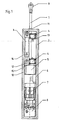
- a circuit breaker is provided with a housing 2, preferably a plastic housing. This can be closed with a door, not shown, via the lid seal 10 waterproof.
- a Differentialstellzylinder 3 is actuated, which is mechanically coupled via a driver 12 with the control rod 1, which transmits the actuating force directly via the clevis 9 on a switch element, not shown.
- the control rod 1 is guided by rod guides 11 and 15, the upper also comprising a watertight seal.
- the positioning movement is carried out in both directions in the same direction.
- the force is also identical, but variably adjustable. However, different force profiles can be realized with simple means.
- An actuation of the remote control unit for disconnectors is possible only by a control of the electric motor 7, alternatively by electro- or hand-hydraulic adjustment.
- the manual adjustment is carried out by means of pumping movement on the hand pump 6 with a knob, not shown, and preferably housed in the housing door knob.
- the embodiment is illustrative and not limiting.
Landscapes
- Driving Mechanisms And Operating Circuits Of Arc-Extinguishing High-Tension Switches (AREA)
- Fluid-Pressure Circuits (AREA)
- Mechanisms For Operating Contacts (AREA)
- Push-Button Switches (AREA)
- Switches Operated By Changes In Physical Conditions (AREA)
- Glass Compositions (AREA)
Claims (9)
- Dispositif d'entraînement pour un sectionneur comprenant un boîtier (2) dans lequel sont disposés un actionneur (1), une unité de génération et de transmission de force motrice pour mouvoir l'actionneur (1) et une unité de commande (13),l'unité de génération et de transmission de force motrice étant électrohydraulique et comprenant un moteur d'entraînement (7) électrique, une pompe hydraulique (8) et un vérin hydraulique (3) qui est couplé mécaniquement à l'actionneur (1),
caractérisé en ce que
le vérin hydraulique (3) est couplé mécaniquement par l'intermédiaire d'un entraîneur (12) à l'actionneur (1). - Dispositif d'entraînement selon la revendication 1, caractérisé en ce que le vérin hydraulique (3) est un vérin de commande différentiel.
- Dispositif d'entraînement selon la revendication 1 ou 2, caractérisé par une pompe hydraulique manuelle.
- Dispositif d'entraînement selon l'une quelconque des revendications précédentes, caractérisé par un moyen de blocage (14) hydraulique.
- Dispositif d'entraînement selon l'une quelconque des revendications précédentes, caractérisé par un interrupteur de position de fin de course (4) électrique réglable.
- Dispositif d'entraînement selon l'une quelconque des revendications précédentes, caractérisé en ce que l'unité de commande (13) est conçue pour une réception de signal sans fil.
- Dispositif d'entraînement selon l'une quelconque des revendications précédentes, caractérisé en ce que cette énergie électrique nécessaire pour un fonctionnement du moteur d'entraînement (7) électrique provient au moins partiellement d'un générateur hélioélectrique.
- Dispositif d'entraînement selon l'une quelconque des revendications précédentes, caractérisé en ce que le boîtier peut être fermé de façon étanche à l'eau.
- Dispositif d'entraînement selon l'une quelconque des revendications précédentes, caractérisé en ce qu'un interrupteur de sécurité est disposé sur un couvercle de boîtier.
Applications Claiming Priority (2)
| Application Number | Priority Date | Filing Date | Title |
|---|---|---|---|
| DE29812474U DE29812474U1 (de) | 1998-07-15 | 1998-07-15 | Trennschalter |
| DE29812474U | 1998-07-15 |
Publications (3)
| Publication Number | Publication Date |
|---|---|
| EP0973183A2 EP0973183A2 (fr) | 2000-01-19 |
| EP0973183A3 EP0973183A3 (fr) | 2000-11-08 |
| EP0973183B1 true EP0973183B1 (fr) | 2006-12-13 |
Family
ID=8059809
Family Applications (1)
| Application Number | Title | Priority Date | Filing Date |
|---|---|---|---|
| EP99113484A Expired - Lifetime EP0973183B1 (fr) | 1998-07-15 | 1999-07-13 | Dispositif d'entraînement pour un sectionneur |
Country Status (3)
| Country | Link |
|---|---|
| EP (1) | EP0973183B1 (fr) |
| AT (1) | ATE348398T1 (fr) |
| DE (2) | DE29812474U1 (fr) |
Families Citing this family (2)
| Publication number | Priority date | Publication date | Assignee | Title |
|---|---|---|---|---|
| DE102010003787A1 (de) | 2010-04-09 | 2011-10-13 | Siemens Aktiengesellschaft | Antriebseinrichtung zur Fernbetätigung eines Schalters |
| DE102010032125B4 (de) * | 2010-07-24 | 2017-05-04 | Hilde Schlögl | Steuerungskasten sowie Steuervorrichtung für Nutzfahrzeuge |
Family Cites Families (4)
| Publication number | Priority date | Publication date | Assignee | Title |
|---|---|---|---|---|
| US4118613A (en) | 1977-06-27 | 1978-10-03 | General Electric Company | Hydraulically-actuated operating system for an electric circuit breaker |
| DE3710376A1 (de) * | 1987-03-28 | 1988-10-13 | Asea Brown Boveri | Antriebseinrichtung fuer einen beweglichen kontaktarm eines elektrischen schaltgeraetes |
| DE3833484A1 (de) | 1988-10-01 | 1990-04-05 | Asea Brown Boveri | Antriebsvorrichtung fuer ein elektrisches schaltgeraet |
| US5534858A (en) * | 1994-01-14 | 1996-07-09 | System Analysis & Integration, Inc. | Poletop switch automation system |
-
1998
- 1998-07-15 DE DE29812474U patent/DE29812474U1/de not_active Expired - Lifetime
-
1999
- 1999-07-13 EP EP99113484A patent/EP0973183B1/fr not_active Expired - Lifetime
- 1999-07-13 DE DE59914049T patent/DE59914049D1/de not_active Expired - Lifetime
- 1999-07-13 AT AT99113484T patent/ATE348398T1/de not_active IP Right Cessation
Also Published As
| Publication number | Publication date |
|---|---|
| DE59914049D1 (de) | 2007-01-25 |
| ATE348398T1 (de) | 2007-01-15 |
| DE29812474U1 (de) | 1998-11-12 |
| EP0973183A3 (fr) | 2000-11-08 |
| EP0973183A2 (fr) | 2000-01-19 |
Similar Documents
| Publication | Publication Date | Title |
|---|---|---|
| DE69905065T2 (de) | Gasisolierte schaltvorrichtung | |
| DE19539753B4 (de) | Kraftfahrzeugtürverschluß mit Zentralverriegelungseinrichtung | |
| EP1687834B1 (fr) | Mecanisme d'entrainement par arbre destine a un disjoncteur et/ou un interrupteur de mise a la terre | |
| DE10236372A1 (de) | Antriebsmotor für Verstelleinrichtungen in Kraftfahrzeugen | |
| DE19949453B4 (de) | Automatische Tür- oder Fensteranlage | |
| DE19537504A1 (de) | Fahrzeugtür | |
| DE69023195T2 (de) | Steuermechanismus für einen multipolaren Hochspannungsschalter. | |
| EP0973183B1 (fr) | Dispositif d'entraînement pour un sectionneur | |
| EP3483375B1 (fr) | Dispositif d'actionnement, au moins partiellement automatique, d'un vantail de porte | |
| EP4364175B1 (fr) | Entrainement pour actionner un dispositif de commutation électrique et appareil pour commutation de réseau | |
| DE102005012208A1 (de) | Fahrzeugfensteröffnungssystem | |
| EP2817808A1 (fr) | Ensemble d'entraînement pour commutateur à gradins | |
| DE2824510A1 (de) | Vorrichtung zum steuern der torbewegung von elektrisch betriebenen toren | |
| EP3348764B1 (fr) | Dispositif d'actionnement au moins partiellement automatique d'un vantail de porte | |
| EP0864722B1 (fr) | Dispositif pour une déconnexion d'entraínement d'un moteur | |
| DE102012108877A1 (de) | Mittelspannungs-Schalteinrichtung | |
| EP0839980B1 (fr) | Commande électrique de porte de garage | |
| DE102004054258B3 (de) | Betätigungsvorrichtung zur Steuerung des Gangwechsels eines Kraftfahrzeuggetriebes | |
| DE19755942A1 (de) | Fahrzeugtür | |
| DE2942793C2 (de) | Elektromotorisch angetriebene Verstelleinrichtung | |
| DE19955301A1 (de) | Schalterfernantrieb | |
| EP3348765B1 (fr) | Dispositif d'actionnement au moins partiellement automatique d'un vantail de porte | |
| DE10239181B4 (de) | Elektromechanischer Antrieb für ein Tor und Verfahren zum Betrieb eines elektromechanischen Antriebes für ein Tor | |
| DE102010003787A1 (de) | Antriebseinrichtung zur Fernbetätigung eines Schalters | |
| DE19853508C2 (de) | Antrieb für Miniaturmodelle |
Legal Events
| Date | Code | Title | Description |
|---|---|---|---|
| PUAI | Public reference made under article 153(3) epc to a published international application that has entered the european phase |
Free format text: ORIGINAL CODE: 0009012 |
|
| AK | Designated contracting states |
Kind code of ref document: A2 Designated state(s): AT DE |
|
| AX | Request for extension of the european patent |
Free format text: AL;LT;LV;MK;RO;SI |
|
| PUAL | Search report despatched |
Free format text: ORIGINAL CODE: 0009013 |
|
| AK | Designated contracting states |
Kind code of ref document: A3 Designated state(s): AT BE CH CY DE DK ES FI FR GB GR IE IT LI LU MC NL PT SE |
|
| AX | Request for extension of the european patent |
Free format text: AL;LT;LV;MK;RO;SI |
|
| 17P | Request for examination filed |
Effective date: 20010508 |
|
| AKX | Designation fees paid |
Free format text: AT DE |
|
| GRAP | Despatch of communication of intention to grant a patent |
Free format text: ORIGINAL CODE: EPIDOSNIGR1 |
|
| RTI1 | Title (correction) |
Free format text: DRIVE DEVICE FOR AN ISOLATING SWITCH |
|
| RAP1 | Party data changed (applicant data changed or rights of an application transferred) |
Owner name: CONTEC GMBH TRANSPORTATION SYSTEMS |
|
| RIN1 | Information on inventor provided before grant (corrected) |
Inventor name: CONTEC GMBH TRANSPORTATION SYSTEMS |
|
| GRAS | Grant fee paid |
Free format text: ORIGINAL CODE: EPIDOSNIGR3 |
|
| GRAA | (expected) grant |
Free format text: ORIGINAL CODE: 0009210 |
|
| RIN1 | Information on inventor provided before grant (corrected) |
Inventor name: PUETZ, SIEGFRIED |
|
| AK | Designated contracting states |
Kind code of ref document: B1 Designated state(s): AT DE |
|
| REF | Corresponds to: |
Ref document number: 59914049 Country of ref document: DE Date of ref document: 20070125 Kind code of ref document: P |
|
| PLBE | No opposition filed within time limit |
Free format text: ORIGINAL CODE: 0009261 |
|
| STAA | Information on the status of an ep patent application or granted ep patent |
Free format text: STATUS: NO OPPOSITION FILED WITHIN TIME LIMIT |
|
| 26N | No opposition filed |
Effective date: 20070914 |
|
| PGFP | Annual fee paid to national office [announced via postgrant information from national office to epo] |
Ref country code: AT Payment date: 20090715 Year of fee payment: 11 |
|
| PG25 | Lapsed in a contracting state [announced via postgrant information from national office to epo] |
Ref country code: AT Free format text: LAPSE BECAUSE OF NON-PAYMENT OF DUE FEES Effective date: 20100713 |
|
| PGFP | Annual fee paid to national office [announced via postgrant information from national office to epo] |
Ref country code: DE Payment date: 20140731 Year of fee payment: 16 |
|
| REG | Reference to a national code |
Ref country code: DE Ref legal event code: R119 Ref document number: 59914049 Country of ref document: DE |
|
| PG25 | Lapsed in a contracting state [announced via postgrant information from national office to epo] |
Ref country code: DE Free format text: LAPSE BECAUSE OF NON-PAYMENT OF DUE FEES Effective date: 20160202 |