EP0973221A1 - Pile secondaire au lithium - Google Patents
Pile secondaire au lithium Download PDFInfo
- Publication number
- EP0973221A1 EP0973221A1 EP99113718A EP99113718A EP0973221A1 EP 0973221 A1 EP0973221 A1 EP 0973221A1 EP 99113718 A EP99113718 A EP 99113718A EP 99113718 A EP99113718 A EP 99113718A EP 0973221 A1 EP0973221 A1 EP 0973221A1
- Authority
- EP
- European Patent Office
- Prior art keywords
- electrode
- lithium secondary
- secondary battery
- total thickness
- negative electrode
- Prior art date
- Legal status (The legal status is an assumption and is not a legal conclusion. Google has not performed a legal analysis and makes no representation as to the accuracy of the status listed.)
- Granted
Links
Images


Classifications
-
- H—ELECTRICITY
- H01—ELECTRIC ELEMENTS
- H01M—PROCESSES OR MEANS, e.g. BATTERIES, FOR THE DIRECT CONVERSION OF CHEMICAL ENERGY INTO ELECTRICAL ENERGY
- H01M10/00—Secondary cells; Manufacture thereof
- H01M10/05—Accumulators with non-aqueous electrolyte
- H01M10/058—Construction or manufacture
- H01M10/0587—Construction or manufacture of accumulators having only wound construction elements, i.e. wound positive electrodes, wound negative electrodes and wound separators
-
- H—ELECTRICITY
- H01—ELECTRIC ELEMENTS
- H01M—PROCESSES OR MEANS, e.g. BATTERIES, FOR THE DIRECT CONVERSION OF CHEMICAL ENERGY INTO ELECTRICAL ENERGY
- H01M10/00—Secondary cells; Manufacture thereof
- H01M10/05—Accumulators with non-aqueous electrolyte
- H01M10/052—Li-accumulators
- H01M10/0525—Rocking-chair batteries, i.e. batteries with lithium insertion or intercalation in both electrodes; Lithium-ion batteries
-
- H—ELECTRICITY
- H01—ELECTRIC ELEMENTS
- H01M—PROCESSES OR MEANS, e.g. BATTERIES, FOR THE DIRECT CONVERSION OF CHEMICAL ENERGY INTO ELECTRICAL ENERGY
- H01M4/00—Electrodes
- H01M4/02—Electrodes composed of, or comprising, active material
- H01M4/13—Electrodes for accumulators with non-aqueous electrolyte, e.g. for lithium-accumulators; Processes of manufacture thereof
-
- H—ELECTRICITY
- H01—ELECTRIC ELEMENTS
- H01M—PROCESSES OR MEANS, e.g. BATTERIES, FOR THE DIRECT CONVERSION OF CHEMICAL ENERGY INTO ELECTRICAL ENERGY
- H01M10/00—Secondary cells; Manufacture thereof
- H01M10/42—Methods or arrangements for servicing or maintenance of secondary cells or secondary half-cells
- H01M2010/4292—Aspects relating to capacity ratio of electrodes/electrolyte or anode/cathode
-
- H—ELECTRICITY
- H01—ELECTRIC ELEMENTS
- H01M—PROCESSES OR MEANS, e.g. BATTERIES, FOR THE DIRECT CONVERSION OF CHEMICAL ENERGY INTO ELECTRICAL ENERGY
- H01M4/00—Electrodes
- H01M4/02—Electrodes composed of, or comprising, active material
- H01M4/36—Selection of substances as active materials, active masses, active liquids
- H01M4/48—Selection of substances as active materials, active masses, active liquids of inorganic oxides or hydroxides
- H01M4/50—Selection of substances as active materials, active masses, active liquids of inorganic oxides or hydroxides of manganese
- H01M4/505—Selection of substances as active materials, active masses, active liquids of inorganic oxides or hydroxides of manganese of mixed oxides or hydroxides containing manganese for inserting or intercalating light metals, e.g. LiMn2O4 or LiMn2OxFy
-
- H—ELECTRICITY
- H01—ELECTRIC ELEMENTS
- H01M—PROCESSES OR MEANS, e.g. BATTERIES, FOR THE DIRECT CONVERSION OF CHEMICAL ENERGY INTO ELECTRICAL ENERGY
- H01M4/00—Electrodes
- H01M4/02—Electrodes composed of, or comprising, active material
- H01M4/36—Selection of substances as active materials, active masses, active liquids
- H01M4/58—Selection of substances as active materials, active masses, active liquids of inorganic compounds other than oxides or hydroxides, e.g. sulfides, selenides, tellurides, halogenides or LiCoFy; of polyanionic structures, e.g. phosphates, silicates or borates
- H01M4/583—Carbonaceous material, e.g. graphite-intercalation compounds or CFx
- H01M4/587—Carbonaceous material, e.g. graphite-intercalation compounds or CFx for inserting or intercalating light metals
-
- Y—GENERAL TAGGING OF NEW TECHNOLOGICAL DEVELOPMENTS; GENERAL TAGGING OF CROSS-SECTIONAL TECHNOLOGIES SPANNING OVER SEVERAL SECTIONS OF THE IPC; TECHNICAL SUBJECTS COVERED BY FORMER USPC CROSS-REFERENCE ART COLLECTIONS [XRACs] AND DIGESTS
- Y02—TECHNOLOGIES OR APPLICATIONS FOR MITIGATION OR ADAPTATION AGAINST CLIMATE CHANGE
- Y02E—REDUCTION OF GREENHOUSE GAS [GHG] EMISSIONS, RELATED TO ENERGY GENERATION, TRANSMISSION OR DISTRIBUTION
- Y02E60/00—Enabling technologies; Technologies with a potential or indirect contribution to GHG emissions mitigation
- Y02E60/10—Energy storage using batteries
-
- Y—GENERAL TAGGING OF NEW TECHNOLOGICAL DEVELOPMENTS; GENERAL TAGGING OF CROSS-SECTIONAL TECHNOLOGIES SPANNING OVER SEVERAL SECTIONS OF THE IPC; TECHNICAL SUBJECTS COVERED BY FORMER USPC CROSS-REFERENCE ART COLLECTIONS [XRACs] AND DIGESTS
- Y02—TECHNOLOGIES OR APPLICATIONS FOR MITIGATION OR ADAPTATION AGAINST CLIMATE CHANGE
- Y02P—CLIMATE CHANGE MITIGATION TECHNOLOGIES IN THE PRODUCTION OR PROCESSING OF GOODS
- Y02P70/00—Climate change mitigation technologies in the production process for final industrial or consumer products
- Y02P70/50—Manufacturing or production processes characterised by the final manufactured product
-
- Y—GENERAL TAGGING OF NEW TECHNOLOGICAL DEVELOPMENTS; GENERAL TAGGING OF CROSS-SECTIONAL TECHNOLOGIES SPANNING OVER SEVERAL SECTIONS OF THE IPC; TECHNICAL SUBJECTS COVERED BY FORMER USPC CROSS-REFERENCE ART COLLECTIONS [XRACs] AND DIGESTS
- Y02—TECHNOLOGIES OR APPLICATIONS FOR MITIGATION OR ADAPTATION AGAINST CLIMATE CHANGE
- Y02T—CLIMATE CHANGE MITIGATION TECHNOLOGIES RELATED TO TRANSPORTATION
- Y02T10/00—Road transport of goods or passengers
- Y02T10/60—Other road transportation technologies with climate change mitigation effect
- Y02T10/70—Energy storage systems for electromobility, e.g. batteries
Definitions
- This invention relates to a lithium secondary battery to be suitably used in particular to drive a motor of an electric vehicle, etc., and in more particular to a lithium secondary battery which can reduce internal resistance, and attain good charging-discharging characteristics as well as an high output and a huge current by setting shape parameters of an internal electrode body under predetermined conditions.
- a lithium secondary battery with a large energy density is expected as a promising battery, but a lithium secondary battery is required to attain characteristics such as large capacity as well as a high output so as to attain predetermined acceleration performance, slope-climbing performance, and continuous running performance, etc.
- an HEV is in a mode to assist an output power at the time of acceleration, and therefore, a high output is required for a battery to drive a motor.
- the voltage per battery depends on materials configuring the battery, and in the case of a lithium secondary battery, the voltage is approximately 4.2 V at highest, and a huge output means a huge current to flow.
- the internal resistance of a battery is determined by the resistance value of a configuring members of a battery, and especially, it is extremely important that the resistance of an internal electrode body (charge-discharge unit) to be regarded as a central part of a battery should be reduced.
- lithium secondary batteries currently in practical use for electric appliances, are not with large battery capacities, and in few cases that large currents are required in their use, therefore no detailed studies on resistance of internal electrode body in a battery have been conducted to date.
- Japanese Patent Laid-Open No. 2701347 specification discloses a lithium secondary battery comprising a band-shape positive electrode, and a band-shape negative electrode, the both electrodes being wound each other to configure a wound body, wherein the positive active material layer configuring the band-shape positive electrode and the negative active material layer configuring the band-shape negative electrode have predetermined thickness respectively, and the ratio of respective thickness falls in within a predetermined range.
- the lithium secondary battery disclosed in this Japanese Patent Laid-Open No. 2701347 specification is the one having regulated the form of elements to configure the internal electrode body, nevertheless the resistance of the internal electrode body has not been studied. That is, in spite that thickness of an electrode active material layer is a factor to affect resistance of an internal electrode body, which point has not been discussed, and in addition, no consideration has been given to the influence of the resistance of electrode substrate (current collector (metal foil)) itself which is indispensable to configure a band-shape electrode as well as of band-shape electrode itself to the resistance of the internal electrode body.
- electrode substrate current collector (metal foil)
- a lithium secondary battery disclosed in Japanese Patent Laid-Open No. 2701347 specification has been made mainly to be used as a power source of an electronic appliance, aiming at fulfilling requirement for larger capacity, that is, mainly aiming at improvement in energy density, and in addition, aiming at prevention of occurrence of cracks in an electrode, and therefore, in Japanese Patent Laid-Open No. 2701347 specification no descriptions that higher output has been the purpose thereof are found.
- Japanese Patent Laid-Open No. 2701347 specification describes that it is preferable that lithium cobalt oxide (LiCoO 2 ) with a large lithium capacity as the positive active material is used since the disclosed lithium secondary battery is attained with the main purpose having been set at improvement of energy density as described before.
- lithium cobalt oxide LiCoO 2
- the quantity of lithium in a positive active material may be less to fall within a range which can secure the predetermined quantity, and instead the use of positive active material making resistance of the positive active material layer smaller is regarded as more important.
- weight should be preferably lighter if the battery capacity is the same.
- the volume of a battery is smaller, less mounting space is required in a vehicle, preferably resulting in larger freedom in space designing.
- a lithium secondary battery comprising a positive electrode, a negative electrode, a separator, and an internal electrode body, an organic electrolyte, the positive electrode and the negative electrode being wound through the separator so that the positive electrode and the negative electrode are not brought into direct contact with each other, wherein a total thickness ( ⁇ m) of electrode substrates is divided by a total thickness ( ⁇ m) of electrode active material layers, the resultant ratio being a total thickness ratio, which total thickness ratio is not less than 0.045 and not more than 0.31.
- the value of this ratio is not less than 0.05 and not more than 0.25.
- a lithium secondary battery comprising a positive electrode, a negative electrode, a separator, and an internal electrode body, an organic electrolyte, the positive electrode and the negative electrode being wound through the separator so that the positive electrode and the negative electrode are not brought into direct contact with each other, wherein when the number of winding (round/cm) of the positive electrode or the negative electrode per unit length along the direction of diameter of the internal electrode body is multiplied by total thickness (cm) of the electrode active material layers, being designated as a correction winding density (round), the correction winding density is not less than 0.73 (round).
- LiMn 2 O 4 spinel is preferably used as a positive electrode active material to be used for the positive electrode, and at that time, LiMn 2 O 4 spinel having Li/Mn ratio of more than 0.5 is used more preferably.
- a negative active material to be used in the negative electrode highly graphitized carbon material is suitably used and the one in form of fiber quality is used more preferably.
- the lithium secondary battery according to the present invention is designed to go with reduction in battery's internal resistance and to attain higher output, and thus can be suitably used as the one for an electric vehicle (EV) or a hybrid electric vehicle (HEV).
- the battery hereof is suitably applied to a battery having battery capacity of not less than 5 Ah which gives remarkable effects with higher output.
- An internal electrode body of a lithium secondary battery in the present invention (hereinafter to be referred to as a battery) is configured by comprising a positive electrode, a negative electrode, and a separator made of porous polymer film, the positive electrode and the negative electrode being wound through the separator so that the positive electrode and the negative electrode are not brought into direct contact with each other.
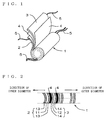
- the internal electrode body 1 is formed by winding a positive electrode 2 and a negative electrode 3 through a separator 4, and the respective positive and negative electrode plates 2 and 3 (hereafter to be referred to as electrodes 2 and 3) are provided with tabs 5.
- tabs 5 can be attached to the electrodes 2 and 3 by ultrasonic welding or the like at the time when the electrodes 2 and 3 are wound with the separator 4. Incidentally, the opposite end of each tab 5 which end has been connected to the electrodes 2 and 3 is attached to an output terminal (not shown) or a current extraction terminal (not shown) being conductive to the output terminal.
- the positive electrode 2 comprises metal foils and electrode active materials, the metal foil made of aluminum, and titanium, etc. for the positive electrode 2 and the metal foil made of copper and nickel, etc. for the negative electrode 3 being assigned as electrode substrates (electricity collection bodies), with electrode active materials being coated on the both sides of respective metal foils to form electrode active material layers to produce the electrodes 2 and 3.
- the tabs 5 are disposed along one side of such metal foils, and generally thin band type ones are used so that portions in the electrodes 2 and 3 where tabs 5 have been attached may not swell toward outer circumference at the time when the internal electrode body 1 has been formed.
- the tabs 5 are preferably disposed at an approximately equal distance so that one tab 5 may collect electricity from a fixed area in the electrodes 2 and 3, and in many cases the same material as that of the metal foil where the tab 5 is attached is adopted as the material of the tab 5.
- lithium manganese oxide (LiMn 2 O 4 ) spinel is most suitably used as the positive active material to be used to form the positive electrode 2.
- the LiMn 2 O 4 spinel belongs to the space group Fd3m, and has characteristics that diffusion of Li ions takes place three-dimensionally, and therefore, is more suitable for the purpose of resistance reduction as well as higher output attainment for example with smaller diffusion resistance of Li ions in the battery reaction than in the case where such a material that causes diffusion of Li ions two-dimensionally as in lithium cobalt oxide (LiCoO 2 ) which belongs to a space group R(-3)m ("-" indicates rotational inversion.) and has a layer-shape configuration.
- LiMn 2 O 4 spinel itself has excellent electron conductivity and serves to provide remarkable effects in terms of resistance reduction on the positive electrode 2.
- a battery utilizing LiMn 2 O 4 spinel has excellent characteristics that resistance remains low even under conditions that discharge has been proceeded to an extent, that is, discharge depth is deep, and thus is especially excellent as a battery material for usage which requires higher output discharge.
- LiMn 2 O 4 spinel more preferably, the one with composition of Li/Mn ratio exceeding 0.5 (Li/Mn ratio>0.5), that is, of more excessive Li than stoichiometry composition is to be used, preferably making it possible to plan reduction of resistance remarkably.
- the symbols of chemical elements can be nominated in a list as follows: Fe, Ni, Mg, B, Al, Co, Si, Ti, Sn, P, V, Sb, Nb, Ta, Mo, and W.
- quantity of oxygen for the above-described respective LiMn 2 O 4 spinel is 4 in terms of stoichiometry composition, however, may be changed as far as its crystal configuration is maintained due to valence of proton ions as well as existence of lattice defect, etc.
- LiMn 2 O 4 spinel a lithium transition metal compound oxides such as lithium cobalt oxide (LiCoO 2 ), lithium nickel oxide (LiNiO 2 ), etc. are possibly used, but there is a problem that, as described before, their ion diffusion is two dimensional and has bigger resistance.
- an electrode active material the carbon powder such as acetylene black and graphite powder, etc.
- an amorphous carbon material such as soft carbon or hard carbon, or carbon material such as artificial graphite and natural graphite, etc.
- carbon material such as artificial graphite and natural graphite, etc.
- highly graphitized carbon material and more preferably those having form of fiber are suitably used.
- the negative active materials are different each other in terms of Li capacity, and when a different negative active material is used for a same positive active material, changes are observed in the potential curve, thus it could occur that the desired battery characteristics are not obtainable.
- pitch coke hard carbon
- pitch coke it is difficult to attain high output under deep discharge depth, thus pitch coke is not suitable for the purpose of the present invention.
- each electrode active material of these kinds are in general respectively mixed with various solvents and binders to become a slurry, and thereafter is coated on the surface of the predetermined electrode substrate and fixed, thus the electrodes 2 and 3 are formed.
- the separator 4 it is preferable to use one having a three-layer configuration in which a polyethylene film having lithium ion permeability and including micropores has been sandwiched between porous polypropylene films having lithium ion permeability.
- This serves also as a safety mechanism in which when the temperature of internal electrode body 1 is raised, the polyethylene film is softened at about 130 °C so that the micropores are collapsed to suppress the movement of lithium ions, that is, the battery reaction.
- a nonaqueous organic electrolyte in which one or more kinds of lithium fluoride complex compound such as LiPF 6 , and LiBF 4 , etc. or lithium halide such as LiClO 4 as an electrolyte are dissolved in a single solvent or mixed solvent of organic solvents such as a carbonic acid ester family such as ethylene carbonate (EC), diethyl carbonate (DEC), dimethyl carbonate (DMC) and propylene carbonate (PC), ⁇ -butyrolactone, tetrahydrofuran, and acetonitrile, etc., is preferably used.
- a carbonic acid ester family such as ethylene carbonate (EC), diethyl carbonate (DEC), dimethyl carbonate (DMC) and propylene carbonate (PC), ⁇ -butyrolactone, tetrahydrofuran, and acetonitrile, etc.
- Such an electrolyte fills the internal space of the battery case and consequently permeates into the internal electrode body
- the total thickness ratio is defined by dividing total thickness ( ⁇ m) of electrode substrates with total thickness ( ⁇ m) of electrode active material layers, the total thickness of electrode substrates being the sum of thickness of positive electrode substrate 11 and thickness of negative electrode substrate 12, and total thickness of electrode active material layers being the sum of total thickness of positive electrode active material layer 13 formed on both surfaces of the positive electrode 2 and total thickness of negative electrode active material layer 14 formed on both surfaces of the negative electrode 3, and then this total thickness ratio should be not less than 0.045 and not more than 0.31.
- the unit of thickness of total thickness of electrode substrates and total thickness of electrode active material layers is not limited to " ⁇ m" if their units are the same.
- Table 1 shows characteristics which were obtained when batteries were assembled to have internal electrode bodies with variously different kinds of this total thickness ratio but to have a constant diameter.
- every kind of common material having been used to form the batteries has been described in Table 2.
- Table 1 As can be seen in Table 1, to form the batteries, only thickness of electrode substrates and thickness of electrode active material layers were changed. But, the ratio between thickness of the positive active material layers and thickness of the negative active material layers has been set as a constant. The purpose of this is to avoid making relationship between thickness of the electrode substrate and the internal resistance indistinct due to influence on battery capacity given by the ratio between thickness of the positive active material layer and the negative active material layer.
- the sizes of batteries is fixed at a constant.
- Figs. 3(a) and 3(b) are graphs showing the relationship between the total thickness ratio and the battery's internal resistance as well as energy density in Table 1.
- Figs. 3(a) and 3(b) reveal that the energy density tends to get smaller as the total thickness ratio grow larger.
- the fact that the total thickness ratio is large means that the total thickness of electrode substrates is thick and/or the total thickness of electrode active material layers is thin, but this is an inevitable outcome if any of the cases means that quantity of electrode active materials per unit weight grows less. Accordingly, from the view point of energy density, smaller total thickness ratio is preferable, but in the case where the phenomenon of discharge of a great current has been taken into consideration, internal resistance characteristics are regarded as more important than this energy density.
- any of Figs. 3(a) and 3(b) remarkably reveals that when the total thickness ratio falls within a particular range of values, the internal resistance gets smaller.
- the internal resistance has grown larger by approximately 10% than in the case with the total thickness being 0.05. This is thought to be caused by the fact that resistance of an electrode substrate grows larger when the electrode substrate is too thin.
- the internal resistance has increased by approximately 5%, as compared with the case of the total thickness ratio being 0.306.
- the total thickness ratio within the range not less than 0.045 and not more than 0.31, any big change in internal resistance can be seen.
- a range where no sudden changes in internal resistance take place that is, the range where the total thickness ratio is not less than 0.045 and not more than 0.31, more preferably the range of not less than 0.05 and not more than 0.25, is at the same time the range to be able to control the internal resistance to a small amount, and preferable.
- Reduction in internal resistance not only enables a stable discharge of a huge current but also makes energy loss at the time of charging/discharging smaller, and thus improves the charging/discharging cycle characteristics.
- Figs. 4(a) and 4(b) are graphs showing the relationship between the correction winding density and the battery's internal resistance as well as energy density at the time when the correction winding density (round) has been defined by multiplying the number of winding (round/cm) of the positive electrode 2 or the negative electrode 3 per unit length along the direction of diameter of the internal electrode body 1 with the total thickness (cm) of the electrode active material layers.
- the energy density tends to gets larger. This is caused by the fact that larger number of winding of the electrodes 2 and 3 per unit length along the direction of diameter of the internal electrode body 1 and/or thicker total thickness of the electrode active materials results in larger amount of electrode active materials contributing to the battery reaction.
- the internal resistance gets larger under the condition that the correction winding density decreases to reach not more than 0.69 (round), which is shown in Fig. 4(a) not more remarkably than in Fig. 4(b).
- the correction winding density being not less than 0.69 (round)
- the correction winding density of not less than 0.73 (round) is preferable. Accordingly, as the result of the above, in the present invention, it is judged that the correction winding density of not less than 0.73 (round) can reduce the internal resistance of batteries and preferable.
- the correction winding density is to change as per this winding pressure.
- the winding pressure is heightened too much, it is worried to result in an incident that the electrodes could break, or at a later time the electrolyte could become impermeable to inside the internal electrode body, and as a consequent the battery reaction might not go on well and the internal resistance could increase.
- the winding pressure is insufficient, such a problem that the internal electrode body might not be maintained in a fixed shape could occur. Accordingly, to form a battery, the winding pressure is consequently to be set under predetermined conditions.
- the configuration of the above-described lithium secondary battery of the present invention is suitably applied to huge capacity batteries with the battery capacity of not less than 5 Ah, and in that case, reduction effect of internal resistance remarkably appears. But, it goes without saying that the configuration may be applied to batteries with the capacity of not more than 5 Ah as well. Thus due to small internal resistance, discharge of huge currents becomes feasible without any obstacles, thus the lithium secondary battery of the present invention is suitably used for an electric vehicle (EV) or a hybrid electric vehicle (HEV).
- EV electric vehicle
- HEV hybrid electric vehicle
- the thickness ratio of thickness of electrode substrates and electrode active material layers in electrodes is set at a suitable ratio so that the resistance of the internal electrode body of a battery is reduced, and therefore, the battery can be used without any obstacles for usage such as batteries for an EV as well as an HEV or the like where discharging of huge currents takes place frequently.
- charging/discharging loss is reduced to suppress Jules' heat to be generated, and consequently an excellent effect can be obtained that deterioration of batteries can be controlled and charging/discharging cycle characteristics can be made to get improved.
- the configuration has characteristics that high output characteristics are maintained under conditions of deeper discharging depths.
- a lithium secondary battery includes a positive electrode, a negative electrode, a separator, an internal electrode body, and an organic electrolyte.
- the positive electrode and the negative electrode are wound through the separator so that the positive electrode and the negative electrode are not brought into direct contact with each other.
- a total thickness ( ⁇ m) of electrode substrates is divided by a total thickness ( ⁇ m) of electrode active material layers, and the resultant ratio is a total thickness ratio, which total thickness ratio has been set to be not less than 0.045 and not more than 0.31.
- the lithium secondary battery reduces internal resistance to attain good charging-discharging characteristics and to obtain an high output and a huge current.
Landscapes
- Chemical & Material Sciences (AREA)
- Engineering & Computer Science (AREA)
- Chemical Kinetics & Catalysis (AREA)
- Electrochemistry (AREA)
- General Chemical & Material Sciences (AREA)
- Manufacturing & Machinery (AREA)
- Materials Engineering (AREA)
- Secondary Cells (AREA)
- Battery Electrode And Active Subsutance (AREA)
Applications Claiming Priority (4)
| Application Number | Priority Date | Filing Date | Title |
|---|---|---|---|
| JP19909298 | 1998-07-14 | ||
| JP19909298 | 1998-07-14 | ||
| JP17123899A JP3526786B2 (ja) | 1998-07-14 | 1999-06-17 | リチウム二次電池 |
| JP17123899 | 1999-06-17 |
Publications (2)
| Publication Number | Publication Date |
|---|---|
| EP0973221A1 true EP0973221A1 (fr) | 2000-01-19 |
| EP0973221B1 EP0973221B1 (fr) | 2001-10-17 |
Family
ID=26494036
Family Applications (1)
| Application Number | Title | Priority Date | Filing Date |
|---|---|---|---|
| EP99113718A Expired - Lifetime EP0973221B1 (fr) | 1998-07-14 | 1999-07-13 | Pile secondaire au lithium |
Country Status (5)
| Country | Link |
|---|---|
| US (1) | US6228529B1 (fr) |
| EP (1) | EP0973221B1 (fr) |
| JP (1) | JP3526786B2 (fr) |
| CA (1) | CA2277731C (fr) |
| DE (1) | DE69900355T2 (fr) |
Cited By (4)
| Publication number | Priority date | Publication date | Assignee | Title |
|---|---|---|---|---|
| EP1049189A1 (fr) * | 1999-04-28 | 2000-11-02 | Shin-Kobe Electric Machinery Co. Ltd | Accumulateur aux ions lithium |
| EP0917227A3 (fr) * | 1997-11-10 | 2003-04-09 | Ngk Insulators, Ltd. | Batterie secondaire au lithium |
| GB2460706A (en) * | 2008-06-04 | 2009-12-09 | Lion Cells Inc | Systems and methods for rechargeable battery collector tab configurations and foil thickness |
| CN108352577A (zh) * | 2015-12-01 | 2018-07-31 | 汽车能源供应公司 | 锂离子二次电池及其制造方法 |
Families Citing this family (11)
| Publication number | Priority date | Publication date | Assignee | Title |
|---|---|---|---|---|
| JP3754218B2 (ja) * | 1999-01-25 | 2006-03-08 | 三洋電機株式会社 | 非水電解質電池用正極及びその製造方法、ならびこの正極を用いた非水電解質電池及びその製造方法 |
| JP3368877B2 (ja) * | 1999-11-17 | 2003-01-20 | 新神戸電機株式会社 | 円筒形リチウムイオン電池 |
| US7253585B2 (en) | 2002-11-22 | 2007-08-07 | Milwaukee Electric Tool Corporation | Battery pack |
| US7714538B2 (en) * | 2002-11-22 | 2010-05-11 | Milwaukee Electric Tool Corporation | Battery pack |
| JP5046539B2 (ja) * | 2006-03-24 | 2012-10-10 | 三洋電機株式会社 | ニッケル水素蓄電池 |
| US9608266B2 (en) * | 2007-01-29 | 2017-03-28 | Umicore | Cathode material for lithium-ion rechargeable batteries |
| JP2013012320A (ja) * | 2011-06-28 | 2013-01-17 | Toyota Motor Corp | リチウムイオン二次電池 |
| JP6184810B2 (ja) * | 2013-09-11 | 2017-08-23 | 日立マクセル株式会社 | 非水二次電池 |
| DE102015218530A1 (de) * | 2015-09-25 | 2017-03-30 | Elringklinger Ag | Gehäuse für eine elektrochemische Zelle und Verfahren zur Herstellung eines Gehäuses für eine elektrochemische Zelle |
| CN106848363A (zh) * | 2015-12-05 | 2017-06-13 | 中山天贸电池有限公司 | 一种提高聚合物薄电池硬度能力的方法 |
| CN112615064B (zh) * | 2021-01-13 | 2022-06-28 | 高德智能科技(河南)股份有限公司 | 一种锂电池卷绕机 |
Citations (6)
| Publication number | Priority date | Publication date | Assignee | Title |
|---|---|---|---|---|
| JPH0256871A (ja) * | 1988-08-23 | 1990-02-26 | Sony Corp | 非水電解液二次電池 |
| EP0573266A1 (fr) * | 1992-06-01 | 1993-12-08 | Kabushiki Kaisha Toshiba | Batterie secondaire au lithium et méthode de fabrication de matière carbonée pour électrode négative de batterie |
| EP0689260A1 (fr) * | 1994-06-01 | 1995-12-27 | Tadiran Ltd. | Pile électrochimique rechargeable |
| EP0771040A2 (fr) * | 1995-09-27 | 1997-05-02 | Sony Corporation | Pile secondaire à haute capacité du type "jelly roll" à électrodes enroulées |
| EP0776056A1 (fr) * | 1995-11-11 | 1997-05-28 | Dai Nippon Printing Co., Ltd. | Plaque d'électrode pour pile secondaire à électrolyte non-aqueux et sa méthode de fabrication |
| EP0887873A2 (fr) * | 1991-09-10 | 1998-12-30 | Bolder Battery, Inc. | Méthode de fabrication des connecteurs terminaux d'une batterie par procédé de moulage de barres de connection (COS) |
-
1999
- 1999-06-17 JP JP17123899A patent/JP3526786B2/ja not_active Expired - Fee Related
- 1999-07-09 US US09/350,519 patent/US6228529B1/en not_active Expired - Lifetime
- 1999-07-12 CA CA002277731A patent/CA2277731C/fr not_active Expired - Fee Related
- 1999-07-13 EP EP99113718A patent/EP0973221B1/fr not_active Expired - Lifetime
- 1999-07-13 DE DE69900355T patent/DE69900355T2/de not_active Expired - Lifetime
Patent Citations (6)
| Publication number | Priority date | Publication date | Assignee | Title |
|---|---|---|---|---|
| JPH0256871A (ja) * | 1988-08-23 | 1990-02-26 | Sony Corp | 非水電解液二次電池 |
| EP0887873A2 (fr) * | 1991-09-10 | 1998-12-30 | Bolder Battery, Inc. | Méthode de fabrication des connecteurs terminaux d'une batterie par procédé de moulage de barres de connection (COS) |
| EP0573266A1 (fr) * | 1992-06-01 | 1993-12-08 | Kabushiki Kaisha Toshiba | Batterie secondaire au lithium et méthode de fabrication de matière carbonée pour électrode négative de batterie |
| EP0689260A1 (fr) * | 1994-06-01 | 1995-12-27 | Tadiran Ltd. | Pile électrochimique rechargeable |
| EP0771040A2 (fr) * | 1995-09-27 | 1997-05-02 | Sony Corporation | Pile secondaire à haute capacité du type "jelly roll" à électrodes enroulées |
| EP0776056A1 (fr) * | 1995-11-11 | 1997-05-28 | Dai Nippon Printing Co., Ltd. | Plaque d'électrode pour pile secondaire à électrolyte non-aqueux et sa méthode de fabrication |
Non-Patent Citations (1)
| Title |
|---|
| PATENT ABSTRACTS OF JAPAN vol. 014, no. 222 (E - 0926) 10 May 1990 (1990-05-10) * |
Cited By (7)
| Publication number | Priority date | Publication date | Assignee | Title |
|---|---|---|---|---|
| EP0917227A3 (fr) * | 1997-11-10 | 2003-04-09 | Ngk Insulators, Ltd. | Batterie secondaire au lithium |
| US6858348B2 (en) | 1997-11-10 | 2005-02-22 | Ngk Insulators, Ltd. | Lithium secondary battery with low internal resistance |
| EP1049189A1 (fr) * | 1999-04-28 | 2000-11-02 | Shin-Kobe Electric Machinery Co. Ltd | Accumulateur aux ions lithium |
| US6447946B1 (en) | 1999-04-28 | 2002-09-10 | Shin-Kobe Electric Machinery Co., Ltd. | Lithium-ion battery |
| GB2460706A (en) * | 2008-06-04 | 2009-12-09 | Lion Cells Inc | Systems and methods for rechargeable battery collector tab configurations and foil thickness |
| US8142928B2 (en) | 2008-06-04 | 2012-03-27 | Basvah Llc | Systems and methods for rechargeable battery collector tab configurations and foil thickness |
| CN108352577A (zh) * | 2015-12-01 | 2018-07-31 | 汽车能源供应公司 | 锂离子二次电池及其制造方法 |
Also Published As
| Publication number | Publication date |
|---|---|
| DE69900355D1 (de) | 2001-11-22 |
| CA2277731A1 (fr) | 2000-01-14 |
| CA2277731C (fr) | 2004-05-11 |
| JP2000090983A (ja) | 2000-03-31 |
| EP0973221B1 (fr) | 2001-10-17 |
| US6228529B1 (en) | 2001-05-08 |
| DE69900355T2 (de) | 2002-07-11 |
| JP3526786B2 (ja) | 2004-05-17 |
Similar Documents
| Publication | Publication Date | Title |
|---|---|---|
| KR102176633B1 (ko) | 리튬 이차전지용 양극 활물질, 그 제조방법 및 이를 포함하는 리튬 이차전지 | |
| EP2541655B1 (fr) | Matériau actif d'électrode positive pour améliorer la puissance de sortie, et accumulateur au lithium comprenant ce matériau | |
| KR101762508B1 (ko) | 리튬 이차전지용 양극활물질, 이의 제조방법 및 이를 포함하는 리튬 이차전지 | |
| JP3866740B2 (ja) | 非水電解質二次電池、組電池及び電池パック | |
| US11784314B2 (en) | Negative electrode for lithium secondary battery and lithium secondary battery including the same | |
| EP0993058B1 (fr) | Pile secondaire au lithium | |
| CN103210526B (zh) | 用于改善输出的锂二次电池用正极材料和包含其的锂二次电池 | |
| JP5219422B2 (ja) | 非水電解質二次電池 | |
| US11735709B2 (en) | Positive electrode for lithium secondary battery, preparation method thereof, and lithium secondary battery including same | |
| EP0973221B1 (fr) | Pile secondaire au lithium | |
| KR20160040117A (ko) | 리튬 이차전지용 양극활물질, 이의 제조방법 및 이를 포함하는 리튬 이차전지 | |
| JP7547627B2 (ja) | リチウム二次電池の製造方法及びこれにより製造されたリチウム二次電池 | |
| US6455198B1 (en) | Lithium secondary battery with a lithium manganese oxide positive electrode | |
| KR20220170622A (ko) | 양극 활물질의 제조방법 | |
| CA3246796A1 (en) | Positive electrode active material and method for producing the same | |
| KR20240001928A (ko) | 리튬 이차 전지 | |
| JP5678569B2 (ja) | リチウムイオン二次電池およびその製造方法 | |
| KR20230027748A (ko) | 리튬 이차전지용 전극 및 이를 포함하는 전극 조립체 | |
| US20240413314A1 (en) | Cathode and Secondary Battery Comprising Same | |
| JP7749866B2 (ja) | 非水電解質電池及び電池パック | |
| US20250002367A1 (en) | Positive electrode active material and lithium secondary battery including the same | |
| US20250140809A1 (en) | Positive electrode active material and lithium secondary battery comprising the same | |
| KR20250013055A (ko) | 이차전지용 전극 조립체 및 이를 포함하는 리튬 이차전지 | |
| CN121844429A (zh) | 锂二次电池以及包含其的电池模块和电池组 | |
| KR20220169775A (ko) | 양극 활물질 전구체, 이의 제조방법 및 이를 이용한 양극 활물질의 제조방법 |
Legal Events
| Date | Code | Title | Description |
|---|---|---|---|
| PUAI | Public reference made under article 153(3) epc to a published international application that has entered the european phase |
Free format text: ORIGINAL CODE: 0009012 |
|
| AK | Designated contracting states |
Kind code of ref document: A1 Designated state(s): BE CH DE FR GB IT LI |
|
| AX | Request for extension of the european patent |
Free format text: AL;LT;LV;MK;RO;SI |
|
| 17P | Request for examination filed |
Effective date: 20000328 |
|
| 17Q | First examination report despatched |
Effective date: 20000531 |
|
| AKX | Designation fees paid |
Free format text: BE CH DE FR GB IT LI |
|
| GRAG | Despatch of communication of intention to grant |
Free format text: ORIGINAL CODE: EPIDOS AGRA |
|
| GRAG | Despatch of communication of intention to grant |
Free format text: ORIGINAL CODE: EPIDOS AGRA |
|
| GRAH | Despatch of communication of intention to grant a patent |
Free format text: ORIGINAL CODE: EPIDOS IGRA |
|
| GRAH | Despatch of communication of intention to grant a patent |
Free format text: ORIGINAL CODE: EPIDOS IGRA |
|
| GRAA | (expected) grant |
Free format text: ORIGINAL CODE: 0009210 |
|
| AK | Designated contracting states |
Kind code of ref document: B1 Designated state(s): BE CH DE FR GB IT LI |
|
| REG | Reference to a national code |
Ref country code: CH Ref legal event code: EP |
|
| REF | Corresponds to: |
Ref document number: 69900355 Country of ref document: DE Date of ref document: 20011122 |
|
| REG | Reference to a national code |
Ref country code: GB Ref legal event code: IF02 |
|
| ET | Fr: translation filed | ||
| REG | Reference to a national code |
Ref country code: CH Ref legal event code: NV Representative=s name: E. BLUM & CO. PATENTANWAELTE |
|
| PLBE | No opposition filed within time limit |
Free format text: ORIGINAL CODE: 0009261 |
|
| STAA | Information on the status of an ep patent application or granted ep patent |
Free format text: STATUS: NO OPPOSITION FILED WITHIN TIME LIMIT |
|
| 26N | No opposition filed | ||
| PGFP | Annual fee paid to national office [announced via postgrant information from national office to epo] |
Ref country code: CH Payment date: 20050725 Year of fee payment: 7 |
|
| PGFP | Annual fee paid to national office [announced via postgrant information from national office to epo] |
Ref country code: BE Payment date: 20050727 Year of fee payment: 7 |
|
| PG25 | Lapsed in a contracting state [announced via postgrant information from national office to epo] |
Ref country code: LI Free format text: LAPSE BECAUSE OF NON-PAYMENT OF DUE FEES Effective date: 20060731 Ref country code: CH Free format text: LAPSE BECAUSE OF NON-PAYMENT OF DUE FEES Effective date: 20060731 Ref country code: BE Free format text: LAPSE BECAUSE OF NON-PAYMENT OF DUE FEES Effective date: 20060731 |
|
| PGFP | Annual fee paid to national office [announced via postgrant information from national office to epo] |
Ref country code: IT Payment date: 20060731 Year of fee payment: 8 |
|
| REG | Reference to a national code |
Ref country code: CH Ref legal event code: PL |
|
| PGFP | Annual fee paid to national office [announced via postgrant information from national office to epo] |
Ref country code: GB Payment date: 20070618 Year of fee payment: 9 |
|
| BERE | Be: lapsed |
Owner name: *NGK INSULATORS LTD Effective date: 20060731 |
|
| GBPC | Gb: european patent ceased through non-payment of renewal fee |
Effective date: 20080713 |
|
| PG25 | Lapsed in a contracting state [announced via postgrant information from national office to epo] |
Ref country code: GB Free format text: LAPSE BECAUSE OF NON-PAYMENT OF DUE FEES Effective date: 20080713 |
|
| PG25 | Lapsed in a contracting state [announced via postgrant information from national office to epo] |
Ref country code: IT Free format text: LAPSE BECAUSE OF NON-PAYMENT OF DUE FEES Effective date: 20070713 |
|
| PGFP | Annual fee paid to national office [announced via postgrant information from national office to epo] |
Ref country code: DE Payment date: 20130711 Year of fee payment: 15 |
|
| PGFP | Annual fee paid to national office [announced via postgrant information from national office to epo] |
Ref country code: FR Payment date: 20130724 Year of fee payment: 15 |
|
| REG | Reference to a national code |
Ref country code: DE Ref legal event code: R119 Ref document number: 69900355 Country of ref document: DE |
|
| REG | Reference to a national code |
Ref country code: FR Ref legal event code: ST Effective date: 20150331 |
|
| PG25 | Lapsed in a contracting state [announced via postgrant information from national office to epo] |
Ref country code: DE Free format text: LAPSE BECAUSE OF NON-PAYMENT OF DUE FEES Effective date: 20150203 |
|
| REG | Reference to a national code |
Ref country code: DE Ref legal event code: R119 Ref document number: 69900355 Country of ref document: DE Effective date: 20150203 |
|
| PG25 | Lapsed in a contracting state [announced via postgrant information from national office to epo] |
Ref country code: FR Free format text: LAPSE BECAUSE OF NON-PAYMENT OF DUE FEES Effective date: 20140731 |