EP1049189A1 - Accumulateur aux ions lithium - Google Patents
Accumulateur aux ions lithium Download PDFInfo
- Publication number
- EP1049189A1 EP1049189A1 EP00301723A EP00301723A EP1049189A1 EP 1049189 A1 EP1049189 A1 EP 1049189A1 EP 00301723 A EP00301723 A EP 00301723A EP 00301723 A EP00301723 A EP 00301723A EP 1049189 A1 EP1049189 A1 EP 1049189A1
- Authority
- EP
- European Patent Office
- Prior art keywords
- lithium
- positive electrode
- battery
- ion battery
- negative electrode
- Prior art date
- Legal status (The legal status is an assumption and is not a legal conclusion. Google has not performed a legal analysis and makes no representation as to the accuracy of the status listed.)
- Granted
Links
Images
Classifications
-
- H—ELECTRICITY
- H01—ELECTRIC ELEMENTS
- H01M—PROCESSES OR MEANS, e.g. BATTERIES, FOR THE DIRECT CONVERSION OF CHEMICAL ENERGY INTO ELECTRICAL ENERGY
- H01M4/00—Electrodes
- H01M4/02—Electrodes composed of, or comprising, active material
- H01M4/36—Selection of substances as active materials, active masses, active liquids
- H01M4/48—Selection of substances as active materials, active masses, active liquids of inorganic oxides or hydroxides
- H01M4/50—Selection of substances as active materials, active masses, active liquids of inorganic oxides or hydroxides of manganese
- H01M4/505—Selection of substances as active materials, active masses, active liquids of inorganic oxides or hydroxides of manganese of mixed oxides or hydroxides containing manganese for inserting or intercalating light metals, e.g. LiMn2O4 or LiMn2OxFy
-
- H—ELECTRICITY
- H01—ELECTRIC ELEMENTS
- H01M—PROCESSES OR MEANS, e.g. BATTERIES, FOR THE DIRECT CONVERSION OF CHEMICAL ENERGY INTO ELECTRICAL ENERGY
- H01M10/00—Secondary cells; Manufacture thereof
- H01M10/05—Accumulators with non-aqueous electrolyte
- H01M10/052—Li-accumulators
- H01M10/0525—Rocking-chair batteries, i.e. batteries with lithium insertion or intercalation in both electrodes; Lithium-ion batteries
-
- H—ELECTRICITY
- H01—ELECTRIC ELEMENTS
- H01M—PROCESSES OR MEANS, e.g. BATTERIES, FOR THE DIRECT CONVERSION OF CHEMICAL ENERGY INTO ELECTRICAL ENERGY
- H01M10/00—Secondary cells; Manufacture thereof
- H01M10/05—Accumulators with non-aqueous electrolyte
- H01M10/058—Construction or manufacture
- H01M10/0587—Construction or manufacture of accumulators having only wound construction elements, i.e. wound positive electrodes, wound negative electrodes and wound separators
-
- H—ELECTRICITY
- H01—ELECTRIC ELEMENTS
- H01M—PROCESSES OR MEANS, e.g. BATTERIES, FOR THE DIRECT CONVERSION OF CHEMICAL ENERGY INTO ELECTRICAL ENERGY
- H01M4/00—Electrodes
- H01M4/02—Electrodes composed of, or comprising, active material
- H01M4/13—Electrodes for accumulators with non-aqueous electrolyte, e.g. for lithium-accumulators; Processes of manufacture thereof
- H01M4/131—Electrodes based on mixed oxides or hydroxides, or on mixtures of oxides or hydroxides, e.g. LiCoOx
-
- H—ELECTRICITY
- H01—ELECTRIC ELEMENTS
- H01M—PROCESSES OR MEANS, e.g. BATTERIES, FOR THE DIRECT CONVERSION OF CHEMICAL ENERGY INTO ELECTRICAL ENERGY
- H01M4/00—Electrodes
- H01M4/02—Electrodes composed of, or comprising, active material
- H01M4/62—Selection of inactive substances as ingredients for active masses, e.g. binders, fillers
- H01M4/624—Electric conductive fillers
- H01M4/625—Carbon or graphite
-
- H—ELECTRICITY
- H01—ELECTRIC ELEMENTS
- H01M—PROCESSES OR MEANS, e.g. BATTERIES, FOR THE DIRECT CONVERSION OF CHEMICAL ENERGY INTO ELECTRICAL ENERGY
- H01M50/00—Constructional details or processes of manufacture of the non-active parts of electrochemical cells other than fuel cells, e.g. hybrid cells
- H01M50/30—Arrangements for facilitating escape of gases
-
- Y—GENERAL TAGGING OF NEW TECHNOLOGICAL DEVELOPMENTS; GENERAL TAGGING OF CROSS-SECTIONAL TECHNOLOGIES SPANNING OVER SEVERAL SECTIONS OF THE IPC; TECHNICAL SUBJECTS COVERED BY FORMER USPC CROSS-REFERENCE ART COLLECTIONS [XRACs] AND DIGESTS
- Y02—TECHNOLOGIES OR APPLICATIONS FOR MITIGATION OR ADAPTATION AGAINST CLIMATE CHANGE
- Y02E—REDUCTION OF GREENHOUSE GAS [GHG] EMISSIONS, RELATED TO ENERGY GENERATION, TRANSMISSION OR DISTRIBUTION
- Y02E60/00—Enabling technologies; Technologies with a potential or indirect contribution to GHG emissions mitigation
- Y02E60/10—Energy storage using batteries
-
- Y—GENERAL TAGGING OF NEW TECHNOLOGICAL DEVELOPMENTS; GENERAL TAGGING OF CROSS-SECTIONAL TECHNOLOGIES SPANNING OVER SEVERAL SECTIONS OF THE IPC; TECHNICAL SUBJECTS COVERED BY FORMER USPC CROSS-REFERENCE ART COLLECTIONS [XRACs] AND DIGESTS
- Y02—TECHNOLOGIES OR APPLICATIONS FOR MITIGATION OR ADAPTATION AGAINST CLIMATE CHANGE
- Y02P—CLIMATE CHANGE MITIGATION TECHNOLOGIES IN THE PRODUCTION OR PROCESSING OF GOODS
- Y02P70/00—Climate change mitigation technologies in the production process for final industrial or consumer products
- Y02P70/50—Manufacturing or production processes characterised by the final manufactured product
-
- Y—GENERAL TAGGING OF NEW TECHNOLOGICAL DEVELOPMENTS; GENERAL TAGGING OF CROSS-SECTIONAL TECHNOLOGIES SPANNING OVER SEVERAL SECTIONS OF THE IPC; TECHNICAL SUBJECTS COVERED BY FORMER USPC CROSS-REFERENCE ART COLLECTIONS [XRACs] AND DIGESTS
- Y10—TECHNICAL SUBJECTS COVERED BY FORMER USPC
- Y10T—TECHNICAL SUBJECTS COVERED BY FORMER US CLASSIFICATION
- Y10T29/00—Metal working
- Y10T29/49—Method of mechanical manufacture
- Y10T29/49002—Electrical device making
- Y10T29/49108—Electric battery cell making
- Y10T29/49115—Electric battery cell making including coating or impregnating
Definitions
- the present invention relates to a lithium-ion battery, and in particular relates to safety and life characteristics of a lithium-ion battery where a winding group having a positive electrode, a negative electrode and at least one separator, and a connecting portion for connecting to respective terminals from the winding group are accommodated in a battery container, and which is provided with an inner pressure-reducing mechanism for discharging gas according to an increase in inner pressure inside the battery container.
- a lithium-ion secondary battery or cell has high energy density as its merit, it is being used as a power supply source for portable equipment mainly as a VTR camera, a note type computer, a portable telephone and the like.
- a winding type structure is formed where a positive electrode member and a negative electrode member, each comprising a strip-shaped metal foil applied with active material, are wound spirally in section such that they are prevented from contacting each other by a separator interposed therebetween, thereby forming a winding group or a winding body.
- the winding group is accommodated in a cylindrical battery can serving as a battery container, and then the can is sealed after pouring electrolytic solution into the can.
- An ordinary cylindrical lithium-ion battery has an external dimension of a diameter of 18mm and a height of 65mm, which is called 18650 type, and it is widely spread as a small-sized lithium-ion battery for a civilian use.
- Lithium cobaltate having high capacity and long life characteristics, is mainly used as positive electrode active material for the 18650 type lithium-ion battery, and battery capacity thereof is approximately 1.3 Ah to 1.7 Ah and battery power (output) thereof is about 10 W or so.
- the safety tends to be regarded as important. Specifically, in such high capacity and high power batteries used as power sources for the EVs and HEVs, the safety is not secured necessarily in the range disclosed in the Japanese Patent No. 2701347. Further, since the high capacity and power batteries are required to allow large current charging and large current discharging, it is difficult to provide such batteries with a current cut-off mechanism (a shutdown switch of a kind) that actuates in response to an increase in inner pressure inside the batteries at an abnormal time, which is generally employed in the 18650 type lithium-ion batteries.
- a current cut-off mechanism a shutdown switch of a kind
- the EV or HEV carries persons or occupants
- safety of a battery used herein means that the behavior of a battery fallen into such abnormal states is not only prevented from injuring vehicle occupants including a driver physically but also it is suppressed from damaging the vehicle body as least as possible.
- carbon material used as negative electrode active material for the lithium-ion battery is in a state in which lithium ions are completely discharged, namely, the carbon material is in a discharged state.
- active material of a discharged state for example, lithium cobaltate (LiCoO 2 ), lithium nickelate (LiNiO 2 ), lithium manganate (LiMn 2 O 4 ) or the like is also used for a positive electrode.
- these active materials for the positive electrode have not sufficient electroconductivity, they are mixed, together with binder, for use with electroconductive powder serving as electroconductive material such as graphite powder, carbon black powder or the like which is stable and inexpensive.
- the lithium manganate having the spinel structure as a crystal structure has a feature that its thermal stability is superior to that of the lithium cobaltate or lithium nickelate. For this reason, a battery where the lithium manganate is used for positive electrode active material is suitable as a high safety battery for a large-sized lithium-ion battery for power storage, the EV or HEV, or the like.
- the crystal of the lithium manganate expands/shrinks according to insertion/department of lithium ions (or occlusion/release thereof) due to charging/discharging. Then, when the charging/discharging accompanied with expansion/shrinking is repeated, the electroconductivity required for the positive electrode deteriorates and the discharging capacity decreases.
- the lithium manganate in the positive electrode where the lithium manganate is used as the active material, its manganese component dissolves into non-aqueous electrolytic solution, irrespective of a charging/discharging state.
- the dissolution of the manganese component causes dropping in a charging/discharging cycle life and/or declining in preserving characteristics.
- JP-A No. 10-182160 discloses a technique for manufacturing lithium manganate with a high crystalline property by improving the structural conditions of the lithium manganate, or by doping additive or the like. JP-A No. 10-182157 also discloses a technique for doping elements of different kinds in the crystalline structure of the lithium manganate. However, a sufficient cycle life has not attained to date.
- an object of the present invention is to provide a lithium-ion battery which retains high safety while having high capacity and high power.
- Another object of the invention is to improve a cycle life of the lithium-ion battery using lithium-manganese complex oxide for a positive electrode.
- a first aspect of the present invention is a lithium-ion battery where a winding group, having a positive electrode, a negative electrode and at least one separator, and a connecting portion for connecting to respective terminals from the winding group are accommodated in a battery container, and which is provided with an inner pressure-reducing mechanism for discharging gas according to an increase in inner pressure inside the battery container, wherein the positive electrode comprises a collector whose both surfaces are applied with composing material including lithium-manganese complex oxide, the thickness of the composing material on the both surfaces of the collector is at least 210 ⁇ m, and the amount of the active material per one surface of the collector is at least 240 g/m 2 .
- the positive electrode comprises the collector whose both surfaces are applied with composing material including lithium-manganese complex oxides.
- the lithium-ion battery when the abnormal state described above occurs, gas is generated due to reaction between electrolytic solution and the composing material including the lithium-manganese complex oxide while maintaining a large current charging state or a large current discharging state, and thereby inner pressure inside the battery container increases in some cases.
- the lithium-ion battery In order to prevent the increase in the inner pressure, the lithium-ion battery generally has an inner pressure-reducing mechanism such as a safety valve, a rupturable valve or the like for discharging gas out of the container at predetermined inner pressure.
- the gas is much gently discharged without any violent discharging from the mechanism. Accordingly, a battery superior in safety can be obtained.
- the negative electrode comprises a second collector whose both surfaces are applied with second composing material including carbon material, and the thickness of the second composing material on the both surfaces of the second collector is set to at least 130 ⁇ m.
- the present inventors have studied eagerly a case in which the lithium manganate is used for the positive electrode, and as a result of it, realized that, when the lithium manganate is used for the positive electrode, the deterioration of the negative electrode is larger than that in a case of using lithium cobaltate for the positive electrode.
- the inventors have also found the causes: Since the volume of the lithium manganate reduces at a time of charging, the pressurizing force of the winding group drops. As this result, collapse in an electroconductive network in the composing material of the negative electrode is brought about. Therefore, in order to achieve the another object, according to a second aspect of the present invention, the lithium-ion battery according to the first aspect, wherein the second composing material contains fiber-shaped or needle-shaped conductive material.
- the conductive material retains the electroconductive network in the composing material of the negative electrode, the cycle characteristic can be improved.
- the conductive material is carbon fibers manufactured by a vapor-phase method or conductive ceramic fibers, and it is more preferable that an average length of the fibers is at least 5 ⁇ m and an average diameter of the fibers is at most 5 ⁇ m.
- Lithium manganate (LiMn 2 O 4 ) powder which is active material, scale-shaped graphite (an average particle size: 20 ⁇ m) which is electroconductive material, and polyvinylidene fluoride (PVDF) which is binder are mixed at a predetermined compounding ratio described later, the obtained mixture is added with N-methyl-2-pyrrolidone (NMP) which is dispersing solvent, and thus added mixture is mixed, thereby producing slurry.
- NMP N-methyl-2-pyrrolidone
- the slurry is applied substantially uniformly and homogeneously to both surfaces of an aluminum foil (positive electrode collector) having the thickness of 20 ⁇ m and serving as a collector.
- an uncoated or unapplied portion having a width of 50 mm is left at one side edge along a longitudinal direction (upper or lower direction in Fig. 1) of the positive electrode member.
- the positive electrode member is dried, pressed and cut, a positive electrode member is obtained having the width of 300 mm, a predetermined length and a predetermined thickness of the applied portion of composing material for the positive electrode as described later.
- the apparent density of the layer of the positive electrode composing material is 2.65 g/cm 3 .
- the above-unapplied portion is notched and a remaining portion thereof forms lead pieces. Also, an interval or space between adjacent lead pieces is set to 20 mm and the width of the lead pieces is set to 10 mm.
- the rolled copper foil thus coated is dried, pressed and cut, thereby obtaining a negative electrode number having the width of 305 mm, a predetermined length and a predetermined thickness of the applied portion of the composing material for the negative electrode as described later.
- the apparent density of the layer of the negative electrode composing material having the predetermined thickness is 1.0 g/cm 3 .
- the above-unapplied portion is notched in the same manner as the positive electrode member, and a remaining portion thereof forms lead pieces. Also, the interval or space between adjacent lead pieces is set to 20 mm and the width of the lead pieces is set to 10 mm.
- the positive electrode member and the negative electrode member thus manufactured are wound with a separator(s) made of polyethylene and a thickness of 40 ⁇ m interposed therebetween, such that they do not contact each other directly.
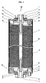
- the lead pieces of the positive electrode member and the lead pieces of the negative electrode member are positioned at both end faces opposed to each other with respect to a winding group 6 (See Fig. 1).
- the lengths of the positive electrode member, the negative electrode member and the separators are adjusted and thus the diameter of the winding group is set to 65 ⁇ 0.1 mm.
- lead pieces 9 extending from the positive electrode member are deformed and all the lead pieces 9 are gathered around a peripheral face of a flange portion 7 spreading from a periphery of a pole strut (a positive electrode external terminal 1) which positions almost on an extending line from a hollow and cylindrical core 15 of the winding group 6.
- a pole strut a positive electrode external terminal 1
- Connecting operation between a negative electrode external terminal 1' and lead pieces 9' extending from the negative electrode member is carried out in the same manner as the connecting operation between the positive electrode external terminal 1 and the lead pieces 9 extending from the positive electrode member.
- an insulating covering 8 is applied on to the entire peripheral face of the flange portions 7 of the positive electrode external terminal 1 and the negative electrode external terminal 1'.
- the insulating covering 8 is also applied on to the entire peripheral face of the winding group 6.
- An adhesive tape comprises a base member formed of polyimide and adhesive agent applied to one surface thereof is used as the insulating covering 8. This adhesive tape is wound several times from the peripheral face of the flange portion 7 to the outer peripheral surface of the winding group 6, thereby forming the insulating covering 8.
- the number of windings of the insulating covering 8 is adjusted such that the insulating covering 8 may exist within the maximum diameter portion of the winding group 6, and the maximum diameter portion is made slightly smaller than the inner diameter of a battery container 5 so that the winding group 6 is inserted into the battery container 5.
- the outer and inner diameters of the battery container 5 are respectively 67 mm and 66 mm.
- second ceramic washers 3' are respectively fitted on the pole strut whose distal end configures the positive electrode external terminal 1 and the pole strut whose distal end configures the negative electrode external terminal 1'.
- Each second washer 3' is made of alumina and has a portion abutting a back face of a disc-shaped battery lid plate 4, whose thickness of the abutting portion, inner diameter and outer diameter are respectively 2mm, 16mm and 25 mm.
- alumina-made first planer ceramic washers 3 having the thickness of 2 mm, the inner diameter of 16 mm and the outer diameter of 28 mm are respectively disposed on the battery lid plates 4, and the positive electrode external terminal 1 and the negative electrode external terminal 1' are respectively inserted in the ceramic washers 3.
- a cleavage valve 10 that cleaves in response to an increase in battery inner pressure is equipped with one side of battery lid plates 4.
- the cleavage valve 10 is set to cleaving pressure of 1.27 to 1.77 ⁇ 10 6 Pa (13 to 18 kg/cm 2 ).
- the nut 2 is screwed to each of the positive electrode external terminal 1 and the negative electrode external terminal 1' to fasten and fix the battery lid plate 4 with the flange portion 7 through the second ceramic washer 3', the first ceramic washer 3 and the metal washer 11.
- the value of the fastening torque was 6.86 N ⁇ m(70 kgf ⁇ cm).
- the metal washer 11 was not rotated until the fastening work was completed.
- a generating element accommodated in the battery container 5 is shut off from the atmosphere by each O-ring 12 made of rubber (EPDM) interposed between the back face of the battery lid plate 4 and the flange portion 7.
- electrolytic solution is poured in a predetermined amount into the battery container 5 through a liquid-pouring opening 13 provided at another side of battery lid plates 4, and then the liquid-pouring opening 13 is sealed so that assembly of a cylindrical lithium-ion battery 20 is completed.
- the electrolytic solution is prepared previously in the following manner: 6-lithium phosphate fluoride (LiPF 6 ) is dissolved at 1 mole/liter into a mixed solution where the volume ratio of ethylene carbonate, dimethyl carbonate and diethyl carbonate is 1:1:1.
- a current cutting-off mechanism which cuts off current in response to an increase in inner pressure inside the battery container 5, is not equipped with the cylindrical lithium-ion battery 20.
- the battery was manufactured in the following manner.
- the compounding ratio of the lithium manganate (LiMn 2 O 4 ) powder, the scale-shaped graphite, and the PVDF was 87 : 8.7 : 4.3 in weight percent (wt%)
- the thickness of the layer of the composing material for the positive electrode active material (hereinafter called “positive electrode composing material layer”) on the both sides (where the thickness of the positive electrode collector is not included) was 210 ⁇ m and the length thereof was 690 cm
- the amount of the active material for the positive material (hereinafter called “positive electrode active material mass”) per one side of the positive electrode collector was 241 g/m 2
- the thickness of the layer of the composing material for the negative electrode active material (hereinafter called “negative electrode composing material layer”) on the both sides (where the thickness of the negative electrode collector is not included) were 130 ⁇ m and the length thereof was 708 cm.
- batteries of Examples 2 to 5 were manufactured according to the same battery manufacturing method as that of the battery of the Example 1 by changing the compounding ratio of the lithium manganate powder, the scale-shaped graphite, and the PVDF, the thickness and the length of the positive electrode composing material layer, the positive electrode active material mass per one side of the positive electrode collector, and the thickness and the length of the negative electrode composing material layer.
- the Table 1 can be seen in the same manner as the case of the Example 1.
- batteries of Controls (Comparative Examples) 1 to 5 was manufactured so as to see the effects of the above Examples.
- the Table 1 can be seen in the same manner as the case of the Example 1.
- lithium cobaltate (LiCoO 2 ) called "Cellseed C-10" (trade name) manufactured by Nippon Chemical Industry Co., Ltd. was used instead of the lithium manganate used in the battery of the Example 1.
- chargeable capacity up to a final voltage of 4.5 V (Li/Li+ reference) of the positive electrode was set to the same as chargeable capacity up to a final voltage of 0 V (Li/Li+ reference) of the negative electrode.
- the chargeable capacity of the active material per unit weight of the lithium manganate was 105 mAh/g
- the chargeable capacity of the active material per unit weight of the lithium cobaltate was 155 mAh/g
- the chargeable capacity of the negative electrode active material was 450 mAh/g.
- the negative electrode member was set to be longer than the positive electrode member by 18 cm such that in a winding direction the positive electrode member neither extends beyond the negative electrode member at the innermost periphery nor even at the outermost periphery of the winding group when winding thereof.
- the width of the negative electrode composing material was set to be longer than that of the positive electrode composing material by 5 mm so as the applied portion of the positive electrode composing material not to extend beyond that of the negative electrode composing material.
- Test 1 Test 2 Discharging Capacity (Ah) Battery Behavior at Continuous Charging Container Deformation Battery Weight (%)
- Example 1 82.40
- Gentle gas discharge from valve Non 81 Example 2 80.34
- Example 3 86.93
- Gentle gas discharge from valve Non 85 Example 4
- 86.11 Gentle gas discharge from valve Non 83
- Example 5 77.04 Gentle gas discharge from valve Non 84
- Control 1 81.41
- Violent gas discharge from valve Non 71 Control 2 84.05
- Violent gas discharge from valve Non 71 Control 3 78.53
- Control 4 109.00
- Violent gas discharge from valve Distended 61 Control 5 82.46 Violent discharge from valve Distended 63
- the lithium manganate serving as the lithium-manganese complex oxide is used for the positive electrode active material
- the thickness of the positive electrode composing material layer on the both surfaces of the positive electrode collector was at least 210 ⁇ m
- the positive electrode active material mass per one side of the positive electrode collector was at least 240 g/m 2
- the lithium-ion batteries' behavior was very gentle even when they fall into the abnormal state, and accordingly, the batteries enabled to realize excellent safety.
- the compounding ratio of the positive electrode active material in the positive electrode composing material is at least 80 wt%. Furthermore, in this case, as shown in the batteries of the Examples 1 to 5, it is preferable that the thickness of the negative electrode composing material layer employing the carbon material as the negative electrode active material is at least 130 ⁇ m.
- the battery as shown in the Control 4, whose positive electrode active material was used other than the lithium manganate, a sufficient safety could not be secured.
- the compounding ratio of the positive electrode active material was reduced so that the capacity was set to the level of the each battery of the Examples.
- the large magnitude of the gas discharge was retained the same.
- the cylindrical lithium-ion battery 20 of the present embodiment behaved very gently even when it was put in the abnormal state and it could be recognized as an excellent battery with high safety.
- the battery with such high capacity, high power and extremely high safety is suitable especially for the power supply source of the EV or HEV.
- the lithium manganate powder, the scale-shaped graphite and the PVDF are mixed at ratio of 80 : 15 : 5 by weight, and the mixture thus obtained is added and mixed with NMP, thereby producing slurry.
- the aluminum foil used is one with 50 mm x 450 mm size in plan, and the apparent density of the positive electrode composing material layer is 2.8 g/cm 3 .
- the "Carbotron P" which is the amorphous carbon, electroconductive material comprising carbon fiber powder or conductive ceramic fiber powder as described later, the PVDF are mixed at a ratio of 85 : 5 : 10 by weight, and the mixture thus obtained is added and mixed with NMP, thereby producing slurry.
- the rolled copper foil used is one with 52 mm x 490 mm size in plan, and the apparent density of the negative electrode composing material layer is 1.0 g/cm 3 .
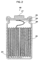
- the positive electrode member and the negative electrode member are wound with a polyethylene separator(s) having the thickness of 25 ⁇ m interposed therebetween to manufacture a winding group 25.
- the winding group 25 is inserted into the battery container 26, and a conductive negative electrode tab terminal 24 welded in advance to the rolled copper foil (a negative electrode collector) serving as a second collector is welded to a bottom face of a battery container 26 having a bottom.
- a conductive positive electrode tab terminal 28 welded in advance to the aluminum foil (a positive electrode collector) is welded to a bottom face of a positive electrode cap 27 having a hat-shaped section.
- a current cutoff mechanism (a pressure switch) operated in accordance with an increase in inner pressure inside the battery such as a PTC (Positive Temperature Coefficient) element or the like, and an inner pressure reducing mechanism such as a safety valve operated at higher pressure than the current cutoff mechanism, are assembled or incorporated.
- the current cutoff mechanism (a pressure switch) with operation pressure of 8.83 x 10⁵ Pa (9 kgf/cm 2 ) and the safety valve with operation pressure of 1.96 x 10⁶ Pa (20 kgf/cm 2 ) were used.
- electrolytic solution used is prepared in the following manner. LiPF 6 was dissolved at 1 mole/liter into a solution where ethylene carbonate and dimethyl carbonate are mixed at a ratio of 1 : 2 by volume.
- the positive electrode cap 27 is disposed on an upper portion of the battery container 26, and the upper portion of the battery container 26 is caulked through an insulating gasket 29 to be sealed so that assembly of a cylindrical lithium-ion battery 30 of 18650 type having a diameter of 18 mm and a height of 65 mm is completed.
- a battery was completed by employing carbon fibers manufactured by a vapor phase method as the conductive material for the negative electrode.
- an average fiber diameter of the carbon fibers was 0.2 ⁇ m and an average fiber length thereof was 15 ⁇ m.
- Example 6 Vapor-phase Carbon Fibers 0.2 15
- Example 7 Acetylene Black Ave.
- Example 8 Potassium Titanate Wiskers Coated with Carbon 05 15
- Example 9 Potassium Titanate Wiskers Coated with Silver 0.6 15
- Example 1 0 Vapor-phase Carbon Fibers 5 15
- Example 1 1 Vapor-phase Carbon Fibers 10 15
- Example 1 2 Vapor-phase Carbon Fibers 0.2 5
- Example 1 3 Vapor-phase Carbon Fibers 5 5
- Example 1 4 Vapor-phase Carbon Fibers 0.2 1 Control 6 - - -
- a battery was completed by employing acetylene black as the conductive material for the negative electrode.
- An average value of primary particle sizes in the acetylene black used was 40 nm.
- a battery was completed by employing potassium titanate whiskers coated with carbon as the conductive material for the negative electrode.
- An average fiber diameter of the carbon-coated potassium titanate whiskers was 0.5 ⁇ m and an average fiber length thereof was 15 ⁇ m.
- a battery was completed by employing potassium titanate whiskers coated with silver as the conductive material for the negative electrode.
- An average fiber diameter of the silver-coated potassium titanate whiskers was 0.6 ⁇ m and an average fiber length thereof was 15 ⁇ m.
- batteries were completed by employing carbon fibers manufactured by a vapor-phase method as the conductive material for the negative electrode, in the same manner as the Example 6.
- manufacturing conditions for carbon fibers were adjusted so that average fiber diameters and average fiber lengths of the carbon fibers were alternated variously in the following manner.
- the average fiber diameter was 5 ⁇ m and the average fiber length was 15 ⁇ m; in the Example 11, the average fiber diameter was 10 ⁇ m and the average fiber length was 15 ⁇ m; in the Example 12, the average fiber diameter was 0.2 ⁇ m and the average fiber length was 5 ⁇ m; in the Example 13, the average fiber diameter was 5 ⁇ m and the average fiber length was 5 ⁇ m; and in the Example 14, the average fiber diameter was 0.2 ⁇ m and the average fiber length was 1 ⁇ m.
- a battery of this Control was completed by employing a negative electrode composing material in which no conductive material was included.
- the negative electrode composing material of this battery was prepared by mixing the amorphous carbon of 90 wt% and the PVDF of 10 wt% at a compounding ratio, and the mixture thus obtained was added and mixed with NMP, thereby producing the slurry.
- charging/discharging cycle test was performed.
- initial discharging capacity of each battery was measured after initial stabilizing operation, and discharging capacity of the 200th cycle was measured after the charging/discharging cycle was repeated under conditions as shown in the following Table 4.
- percentage of the discharging capacity of the 200th cycle to the initial discharging capacity was calculated.
- Discharging Constant Current Discharging 1400mA, 24 min., and 50°C atmosphere Halt time 10 min.
- the batteries of the Examples 6 to 14 containing the conductive material had larger capacity retaining percentage of the 200th cycle than that of the battery of the Control 6. Further, as shown in Table 3 and Table 5, it become obvious that, when the fibers with the average fiber diameter of at most 5 ⁇ m and the average fiber length of at least 5 ⁇ m were contained, a preferable cycle characteristic could be obtained. Incidentally, the same effect as using the potassium titanate whiskers could be obtained when glass fibers were used instead of the potassium titanate whiskers.
- the cylindrical lithium-ion battery 30 with high safety and long cycle life is also suitable for the power supply source for the HEV, as stated above.
- the first embodiment did not refer to the improvement in the cycle characteristic, but it goes without saying that the cycle characteristic in the first embodiment can be improved by using the conductive material shown in the second embodiment.
- the lithium manganate was used for the positive electrode
- the amorphous carbon was used for the negative electrode
- the electrolytic solution was prepared by dissolving the 6-lithium phosphate fluoride at 1 mole/liter into the mixed solution of ethylene carbonate, dimethyl carbonate and the like.
- the binder the negative electrode active material and the non-aqueous electrolytic solution
- the PVDF was used as the binder.
- binders other than the above-mentioned binder, polymers such as Teflon, polyethylene, polystyrene, polybutadiene, butyl rubber (IIR), nitrile rubber, styrene/butadiene rubber, polysulfide rubber, cellulose nitrate, cyanoethyl cellulose, various latex, acrylonitrile, vinyl fluoride, vinylidene fluoride, propyle fluoride chloroprene fluoride and the like, and a mixture thereof can be used.
- lithium-manganese complex oxide into/from which lithium ions can be inserted (occluded) and/or departed (released), and in which lithium ions have been inserted (occluded) in a sufficient amount in advance is preferable.
- Lithium manganate having the spinel structure or each/both site(s) of manganese or lithium in a crystal thereof is(are) replaced or doped with elements other than these elements may be used.
- negative electrode active material for the lithium-ion battery other than ones shown in the above embodiments can be used, which does not limit the present invention.
- natural graphite various artificial graphite materials and cokes may be used.
- the particle shapes of these materials may include scale shape, sphere shape, fiber shape, massive shape and the like, but the active material is not limited to particular shapes.
- an electrolytic solution where an ordinary lithium salt is dissolved as electrolyte into an organic solvent
- the lithium salt and the organic solvent are not limited to these particular ones.
- the electrolyte LiClO 4 , LiAsF 6 , LiPF 6 , LiBF 4 , LiB(C 6 H 5 ) 4 , CH 3 SO 3 Li, CF 3 SO 3 Li and the like, and a mixture thereof may be used.
- organic solvent for the non-aqueous electrolytic solution other than ones shown in the above embodiments, polypropylene carbonate, ethylene carbonate, 1,2-diethxy ethane, 1,2-dimethxy ethane, ⁇ -butyrolactone, tetrahydrofuran, 1,3-dioxolane, 4-methyl-1,3-dioxolane, diethyl ether, sulfolane, methyl sulfolane, acetonitrile, propionitrile or the like, or mixtures of two kinds thereof can be used. Further, the mixture-compounding ratio is not limited to particular ratios.
- the adhesive tape comprising the base material of polyimide and the adhesive agent of hexametha-acrylate applied to one side face thereof was used.
- This invention is not limited to this adhesive tape.
- an adhesive tape comprising a base material of polyolefin such as polypropylene or polyethylene and the like and acrylylic system adhesive agent such as hexametha-acrylate, butyl-acrylate or the like applied to one side surface or both side surfaces of the base material, or a tape without applying adhesive agent thereon and comprising polyolefin or polyimide or the like can also be used preferably.
- the cylindrical lithium-ion batteries were used as the examples, but the present invention is not limited to the cylindrical winding group or the cylindrical battery container. Even when the positive electrode member and the negative electrode member are wound through the separator(s) in a triangle shape, rectangular shape, polygonal shape or the like to be inserted into a battery container, the safety and life characteristics of the battery do not decline.
Landscapes
- Chemical & Material Sciences (AREA)
- Chemical Kinetics & Catalysis (AREA)
- Electrochemistry (AREA)
- General Chemical & Material Sciences (AREA)
- Engineering & Computer Science (AREA)
- Materials Engineering (AREA)
- Manufacturing & Machinery (AREA)
- Inorganic Chemistry (AREA)
- Secondary Cells (AREA)
- Battery Electrode And Active Subsutance (AREA)
- Gas Exhaust Devices For Batteries (AREA)
Applications Claiming Priority (2)
| Application Number | Priority Date | Filing Date | Title |
|---|---|---|---|
| JP12185799 | 1999-04-28 | ||
| JP12185799A JP3541723B2 (ja) | 1999-04-28 | 1999-04-28 | 円筒形リチウムイオン電池 |
Publications (2)
| Publication Number | Publication Date |
|---|---|
| EP1049189A1 true EP1049189A1 (fr) | 2000-11-02 |
| EP1049189B1 EP1049189B1 (fr) | 2002-02-06 |
Family
ID=14821662
Family Applications (1)
| Application Number | Title | Priority Date | Filing Date |
|---|---|---|---|
| EP00301723A Expired - Lifetime EP1049189B1 (fr) | 1999-04-28 | 2000-03-03 | Accumulateur aux ions lithium |
Country Status (5)
| Country | Link |
|---|---|
| US (1) | US6447946B1 (fr) |
| EP (1) | EP1049189B1 (fr) |
| JP (1) | JP3541723B2 (fr) |
| DE (1) | DE60000071T2 (fr) |
| TW (1) | TW452991B (fr) |
Cited By (5)
| Publication number | Priority date | Publication date | Assignee | Title |
|---|---|---|---|---|
| EP1220343A3 (fr) * | 2000-12-26 | 2002-07-17 | Shin-Kobe Electric Machinery Co. Ltd | Pile secondaire à électrolyte non-aqueux |
| FR2855327A1 (fr) * | 2002-10-10 | 2004-11-26 | Sanyo Electric Co | Accumulateur secondaire a electrolyte non acqueux |
| US20100086835A1 (en) * | 2008-10-02 | 2010-04-08 | Jin-Hee Kim | Rechargeable battery |
| KR101049331B1 (ko) * | 2006-07-19 | 2011-07-13 | 도요타지도샤가부시키가이샤 | 리튬 이차 전지 |
| WO2015132193A1 (fr) | 2014-03-04 | 2015-09-11 | Commissariat à l'énergie atomique et aux énergies alternatives | Procédé de fabrication d'une cellule électrochimique élémentaire à électrode à gaz du type métal-gaz et cellule associée |
Families Citing this family (27)
| Publication number | Priority date | Publication date | Assignee | Title |
|---|---|---|---|---|
| JP3511489B2 (ja) * | 1999-10-14 | 2004-03-29 | 日本碍子株式会社 | リチウム二次電池用捲回型電極体の作製方法 |
| JP4027561B2 (ja) * | 2000-03-15 | 2007-12-26 | 新神戸電機株式会社 | 電池 |
| FR2810796B1 (fr) * | 2000-06-26 | 2003-03-21 | Cit Alcatel | Batterie de generateurs electrochimiques comprenant un dispositif de securite |
| JP2002100409A (ja) * | 2000-09-22 | 2002-04-05 | Yuasa Corp | 非水二次電池 |
| JP5052712B2 (ja) * | 2000-12-28 | 2012-10-17 | ソニー株式会社 | 非水電解質二次電池 |
| EP1246277A3 (fr) * | 2001-03-27 | 2004-01-14 | Wilson Greatbatch Ltd. | Trace fusible |
| TW583153B (en) * | 2001-09-25 | 2004-04-11 | Showa Denko Kk | Carbon material, production method and use thereof |
| KR100751772B1 (ko) * | 2003-06-05 | 2007-08-23 | 쇼와 덴코 가부시키가이샤 | 배터리 전극용 탄소재료와 그 제조방법 및 용도 |
| JP5153055B2 (ja) * | 2003-10-31 | 2013-02-27 | 昭和電工株式会社 | リチウム二次電池電極用炭素材料、その製造方法、電極ペースト、リチウム二次電池用電極及びリチウム二次電池 |
| US8617745B2 (en) * | 2004-02-06 | 2013-12-31 | A123 Systems Llc | Lithium secondary cell with high charge and discharge rate capability and low impedance growth |
| EP1716610B1 (fr) * | 2004-02-06 | 2011-08-24 | A 123 Systems, Inc. | Pile secondaire au lithium de haute capacite et a vitesse de charge et de decharge elevee |
| KR100583672B1 (ko) * | 2004-06-07 | 2006-05-26 | 한국전기연구원 | 리튬이차전지용 고출력 극판의 제조방법 |
| JP4688527B2 (ja) * | 2005-03-09 | 2011-05-25 | 日立ビークルエナジー株式会社 | リチウム二次電池 |
| WO2006113924A2 (fr) * | 2005-04-20 | 2006-10-26 | A123 Systems, Inc. | Batterie grande capacite plus sure |
| CN100557859C (zh) * | 2006-07-06 | 2009-11-04 | 伍必翔 | 一种二次锂电池的极卷导电结构 |
| CN100557858C (zh) * | 2006-07-06 | 2009-11-04 | 伍必翔 | 二次锂电池的极卷导电结构 |
| DE102006031857B4 (de) * | 2006-07-10 | 2013-06-06 | Donald P. H. Wu | Sekundäre Lithium-Batterie mit einem leitfähigen, spiral gewickelten Elektrodenaufbau |
| KR101113557B1 (ko) * | 2009-12-16 | 2012-02-24 | 삼성에스디아이 주식회사 | 이차전지 |
| JP5656069B2 (ja) * | 2010-12-13 | 2015-01-21 | ソニー株式会社 | 二次電池、電池パック、電子機器、電動工具、電動車両および電力貯蔵システム |
| CN103636048B (zh) | 2012-02-29 | 2016-12-14 | 新神户电机株式会社 | 锂离子电池 |
| US9306214B2 (en) | 2012-02-29 | 2016-04-05 | Hitachi Chemical Company, Ltd. | Lithium ion battery |
| CN103403945B (zh) | 2012-02-29 | 2016-12-14 | 新神户电机株式会社 | 锂离子电池 |
| WO2013128674A1 (fr) * | 2012-02-29 | 2013-09-06 | 新神戸電機株式会社 | Batterie lithium-ion |
| JP5621933B2 (ja) | 2012-02-29 | 2014-11-12 | 新神戸電機株式会社 | リチウムイオン電池 |
| JP6315230B2 (ja) * | 2013-08-28 | 2018-04-25 | 日立化成株式会社 | リチウムイオン電池 |
| US10121997B1 (en) * | 2014-07-30 | 2018-11-06 | Google Llc | Battery module |
| US20160093842A1 (en) * | 2014-09-30 | 2016-03-31 | Google Inc. | Battery module |
Citations (5)
| Publication number | Priority date | Publication date | Assignee | Title |
|---|---|---|---|---|
| JPH0256871A (ja) * | 1988-08-23 | 1990-02-26 | Sony Corp | 非水電解液二次電池 |
| EP0746047A1 (fr) * | 1995-06-01 | 1996-12-04 | Toray Industries, Inc. | Matériau de carbone amorphe, électrode et accumulateur |
| EP0762521A2 (fr) * | 1995-09-06 | 1997-03-12 | Fuji Photo Film Co., Ltd. | Pile secondaire au Lithium |
| JPH11204107A (ja) * | 1998-01-13 | 1999-07-30 | Shin Kobe Electric Mach Co Ltd | 非水電解液二次電池 |
| EP0973221A1 (fr) * | 1998-07-14 | 2000-01-19 | Ngk Insulators, Ltd. | Pile secondaire au lithium |
Family Cites Families (11)
| Publication number | Priority date | Publication date | Assignee | Title |
|---|---|---|---|---|
| JPS54140941A (en) * | 1978-04-26 | 1979-11-01 | Mitsui Petrochemical Ind | Method of producing battery separator |
| JP2917317B2 (ja) | 1989-10-13 | 1999-07-12 | ソニー株式会社 | 非水電解液二次電池 |
| US5879836A (en) * | 1993-09-10 | 1999-03-09 | Hyperion Catalysis International Inc. | Lithium battery with electrodes containing carbon fibrils |
| US6019802A (en) * | 1994-10-27 | 2000-02-01 | Fuji Photo Film Co., Ltd. | Nonaqueous secondary battery and process for producing the same using a dispersion aid |
| US5686203A (en) * | 1994-12-01 | 1997-11-11 | Fuji Photo Film Co., Ltd. | Non-aqueous secondary battery |
| JPH1040921A (ja) * | 1996-07-26 | 1998-02-13 | Fuji Photo Film Co Ltd | 非水二次電池 |
| JPH10182157A (ja) | 1996-12-24 | 1998-07-07 | Murata Mfg Co Ltd | リチウムマンガン複合酸化物の製造方法 |
| JPH10182160A (ja) | 1996-12-24 | 1998-07-07 | Murata Mfg Co Ltd | リチウムマンガン複合酸化物の製造方法 |
| JPH11111280A (ja) * | 1997-03-14 | 1999-04-23 | Hitachi Maxell Ltd | 水素化物二次電池 |
| JP4000646B2 (ja) * | 1997-12-17 | 2007-10-31 | 宇部興産株式会社 | 二次電池用非水電解液 |
| US6194099B1 (en) * | 1997-12-19 | 2001-02-27 | Moltech Corporation | Electrochemical cells with carbon nanofibers and electroactive sulfur compounds |
-
1999
- 1999-04-28 JP JP12185799A patent/JP3541723B2/ja not_active Expired - Fee Related
-
2000
- 2000-03-03 EP EP00301723A patent/EP1049189B1/fr not_active Expired - Lifetime
- 2000-03-03 DE DE60000071T patent/DE60000071T2/de not_active Expired - Lifetime
- 2000-03-06 US US09/519,464 patent/US6447946B1/en not_active Expired - Lifetime
- 2000-03-28 TW TW089105732A patent/TW452991B/zh not_active IP Right Cessation
Patent Citations (5)
| Publication number | Priority date | Publication date | Assignee | Title |
|---|---|---|---|---|
| JPH0256871A (ja) * | 1988-08-23 | 1990-02-26 | Sony Corp | 非水電解液二次電池 |
| EP0746047A1 (fr) * | 1995-06-01 | 1996-12-04 | Toray Industries, Inc. | Matériau de carbone amorphe, électrode et accumulateur |
| EP0762521A2 (fr) * | 1995-09-06 | 1997-03-12 | Fuji Photo Film Co., Ltd. | Pile secondaire au Lithium |
| JPH11204107A (ja) * | 1998-01-13 | 1999-07-30 | Shin Kobe Electric Mach Co Ltd | 非水電解液二次電池 |
| EP0973221A1 (fr) * | 1998-07-14 | 2000-01-19 | Ngk Insulators, Ltd. | Pile secondaire au lithium |
Non-Patent Citations (2)
| Title |
|---|
| PATENT ABSTRACTS OF JAPAN vol. 014, no. 222 (E - 0926) 10 May 1990 (1990-05-10) * |
| PATENT ABSTRACTS OF JAPAN vol. 1999, no. 12 29 October 1999 (1999-10-29) * |
Cited By (11)
| Publication number | Priority date | Publication date | Assignee | Title |
|---|---|---|---|---|
| EP1220343A3 (fr) * | 2000-12-26 | 2002-07-17 | Shin-Kobe Electric Machinery Co. Ltd | Pile secondaire à électrolyte non-aqueux |
| US6706446B2 (en) | 2000-12-26 | 2004-03-16 | Shin-Kobe Electric Machinery Co., Ltd. | Non-aqueous electrolytic solution secondary battery |
| FR2855327A1 (fr) * | 2002-10-10 | 2004-11-26 | Sanyo Electric Co | Accumulateur secondaire a electrolyte non acqueux |
| US7217475B2 (en) | 2002-10-10 | 2007-05-15 | Sanyo Electric Co., Ltd. | Non-aqueous electrolyte secondary battery |
| KR101049331B1 (ko) * | 2006-07-19 | 2011-07-13 | 도요타지도샤가부시키가이샤 | 리튬 이차 전지 |
| US8257847B2 (en) | 2006-07-19 | 2012-09-04 | Toyota Jidosha Kabushiki Kaisha | Lithium secondary battery |
| US20100086835A1 (en) * | 2008-10-02 | 2010-04-08 | Jin-Hee Kim | Rechargeable battery |
| EP2175507A1 (fr) | 2008-10-02 | 2010-04-14 | Samsung SDI Co., Ltd. | Batterie rechargeable |
| US8993138B2 (en) | 2008-10-02 | 2015-03-31 | Samsung Sdi Co., Ltd. | Rechargeable battery |
| WO2015132193A1 (fr) | 2014-03-04 | 2015-09-11 | Commissariat à l'énergie atomique et aux énergies alternatives | Procédé de fabrication d'une cellule électrochimique élémentaire à électrode à gaz du type métal-gaz et cellule associée |
| US10541455B2 (en) | 2014-03-04 | 2020-01-21 | Commissariat A L'energie Atomique Et Aux Energies Alternatives | Process for manufacturing an elementary gas-electrode electrochemical cell of the metal-gas type and associated cell |
Also Published As
| Publication number | Publication date |
|---|---|
| US6447946B1 (en) | 2002-09-10 |
| DE60000071T2 (de) | 2002-10-02 |
| DE60000071D1 (de) | 2002-03-21 |
| TW452991B (en) | 2001-09-01 |
| JP2000311676A (ja) | 2000-11-07 |
| EP1049189B1 (fr) | 2002-02-06 |
| JP3541723B2 (ja) | 2004-07-14 |
Similar Documents
| Publication | Publication Date | Title |
|---|---|---|
| EP1049189B1 (fr) | Accumulateur aux ions lithium | |
| EP1102342B1 (fr) | Batterie cylindrique aux ions lithium | |
| EP1126538B1 (fr) | Batterie secondaire à électrolyte nonaqueux | |
| EP1220343B1 (fr) | Pile secondaire à électrolyte non-aqueux | |
| EP1542307B1 (fr) | Bloc de batteries et véhicule éléctrique | |
| JP4305035B2 (ja) | 捲回式円筒型リチウムイオン電池 | |
| JP3283805B2 (ja) | リチウム二次電池 | |
| US6803149B2 (en) | Non-aqueous electrolytic solution secondary battery | |
| JP4055307B2 (ja) | 円筒形リチウムイオン電池 | |
| JP4752154B2 (ja) | リチウム二次電池の製造方法 | |
| JP2002015774A (ja) | 非水電解液リチウム二次電池 | |
| JP2000311677A (ja) | 捲回式円筒型リチウム二次電池 | |
| JP3511966B2 (ja) | 円筒形リチウムイオン電池 | |
| JP3988384B2 (ja) | 非水電解液二次電池 | |
| JP4352654B2 (ja) | 非水電解液二次電池 | |
| JP3783503B2 (ja) | リチウム二次電池 | |
| JP4026587B2 (ja) | リチウムイオン電池 | |
| JP3752930B2 (ja) | 円筒形リチウムイオン電池 | |
| JP2004319308A (ja) | リチウム二次電池 | |
| JP3719139B2 (ja) | 非水電解液二次電池 | |
| JP4839517B2 (ja) | 非水電解質二次電池 | |
| JP2000311706A (ja) | 円筒形リチウムイオン電池 | |
| JP3671775B2 (ja) | 円筒形リチウムイオン電池 | |
| JP2002170597A (ja) | 非水電解液二次電池 | |
| JP2001155776A (ja) | 円筒形リチウムイオン電池 |
Legal Events
| Date | Code | Title | Description |
|---|---|---|---|
| PUAI | Public reference made under article 153(3) epc to a published international application that has entered the european phase |
Free format text: ORIGINAL CODE: 0009012 |
|
| AK | Designated contracting states |
Kind code of ref document: A1 Designated state(s): DE FR GB |
|
| AX | Request for extension of the european patent |
Free format text: AL;LT;LV;MK;RO;SI |
|
| 17P | Request for examination filed |
Effective date: 20001128 |
|
| 17Q | First examination report despatched |
Effective date: 20010125 |
|
| GRAG | Despatch of communication of intention to grant |
Free format text: ORIGINAL CODE: EPIDOS AGRA |
|
| AKX | Designation fees paid |
Free format text: DE FR GB |
|
| GRAG | Despatch of communication of intention to grant |
Free format text: ORIGINAL CODE: EPIDOS AGRA |
|
| GRAH | Despatch of communication of intention to grant a patent |
Free format text: ORIGINAL CODE: EPIDOS IGRA |
|
| GRAH | Despatch of communication of intention to grant a patent |
Free format text: ORIGINAL CODE: EPIDOS IGRA |
|
| GRAA | (expected) grant |
Free format text: ORIGINAL CODE: 0009210 |
|
| REG | Reference to a national code |
Ref country code: GB Ref legal event code: IF02 |
|
| AK | Designated contracting states |
Kind code of ref document: B1 Designated state(s): DE FR GB |
|
| REF | Corresponds to: |
Ref document number: 60000071 Country of ref document: DE Date of ref document: 20020321 |
|
| ET | Fr: translation filed | ||
| PLBE | No opposition filed within time limit |
Free format text: ORIGINAL CODE: 0009261 |
|
| STAA | Information on the status of an ep patent application or granted ep patent |
Free format text: STATUS: NO OPPOSITION FILED WITHIN TIME LIMIT |
|
| 26N | No opposition filed |
Effective date: 20021107 |
|
| REG | Reference to a national code |
Ref country code: FR Ref legal event code: PLFP Year of fee payment: 17 |
|
| REG | Reference to a national code |
Ref country code: FR Ref legal event code: PLFP Year of fee payment: 18 |
|
| REG | Reference to a national code |
Ref country code: FR Ref legal event code: PLFP Year of fee payment: 19 |
|
| PGFP | Annual fee paid to national office [announced via postgrant information from national office to epo] |
Ref country code: DE Payment date: 20180220 Year of fee payment: 19 Ref country code: GB Payment date: 20180228 Year of fee payment: 19 |
|
| PGFP | Annual fee paid to national office [announced via postgrant information from national office to epo] |
Ref country code: FR Payment date: 20180223 Year of fee payment: 19 |
|
| REG | Reference to a national code |
Ref country code: DE Ref legal event code: R119 Ref document number: 60000071 Country of ref document: DE |
|
| GBPC | Gb: european patent ceased through non-payment of renewal fee |
Effective date: 20190303 |
|
| PG25 | Lapsed in a contracting state [announced via postgrant information from national office to epo] |
Ref country code: DE Free format text: LAPSE BECAUSE OF NON-PAYMENT OF DUE FEES Effective date: 20191001 Ref country code: GB Free format text: LAPSE BECAUSE OF NON-PAYMENT OF DUE FEES Effective date: 20190303 |
|
| PG25 | Lapsed in a contracting state [announced via postgrant information from national office to epo] |
Ref country code: FR Free format text: LAPSE BECAUSE OF NON-PAYMENT OF DUE FEES Effective date: 20190331 |