EP0973341B1 - Procédé et circuit de traitement de signal vidéo - Google Patents
Procédé et circuit de traitement de signal vidéo Download PDFInfo
- Publication number
- EP0973341B1 EP0973341B1 EP99305610A EP99305610A EP0973341B1 EP 0973341 B1 EP0973341 B1 EP 0973341B1 EP 99305610 A EP99305610 A EP 99305610A EP 99305610 A EP99305610 A EP 99305610A EP 0973341 B1 EP0973341 B1 EP 0973341B1
- Authority
- EP
- European Patent Office
- Prior art keywords
- motion
- image
- signal
- circuit
- frame operation
- Prior art date
- Legal status (The legal status is an assumption and is not a legal conclusion. Google has not performed a legal analysis and makes no representation as to the accuracy of the status listed.)
- Expired - Lifetime
Links
- 238000003672 processing method Methods 0.000 title description 6
- 238000001514 detection method Methods 0.000 claims description 159
- 239000002131 composite material Substances 0.000 claims description 108
- 238000000926 separation method Methods 0.000 claims description 100
- 230000009467 reduction Effects 0.000 claims description 89
- 230000002194 synthesizing effect Effects 0.000 claims description 24
- 238000000034 method Methods 0.000 claims description 6
- 230000003111 delayed effect Effects 0.000 description 8
- 230000001934 delay Effects 0.000 description 7
- 230000000052 comparative effect Effects 0.000 description 4
- 238000010586 diagram Methods 0.000 description 4
- 230000004044 response Effects 0.000 description 4
- 230000015572 biosynthetic process Effects 0.000 description 2
- 230000010354 integration Effects 0.000 description 2
- 238000003786 synthesis reaction Methods 0.000 description 2
- 230000006870 function Effects 0.000 description 1
- 230000006872 improvement Effects 0.000 description 1
Images


Classifications
-
- H—ELECTRICITY
- H04—ELECTRIC COMMUNICATION TECHNIQUE
- H04N—PICTORIAL COMMUNICATION, e.g. TELEVISION
- H04N5/00—Details of television systems
- H04N5/14—Picture signal circuitry for video frequency region
- H04N5/21—Circuitry for suppressing or minimising disturbance, e.g. moiré or halo
-
- H—ELECTRICITY
- H04—ELECTRIC COMMUNICATION TECHNIQUE
- H04N—PICTORIAL COMMUNICATION, e.g. TELEVISION
- H04N9/00—Details of colour television systems
- H04N9/77—Circuits for processing the brightness signal and the chrominance signal relative to each other, e.g. adjusting the phase of the brightness signal relative to the colour signal, correcting differential gain or differential phase
- H04N9/78—Circuits for processing the brightness signal and the chrominance signal relative to each other, e.g. adjusting the phase of the brightness signal relative to the colour signal, correcting differential gain or differential phase for separating the brightness signal or the chrominance signal from the colour television signal, e.g. using comb filter
-
- H—ELECTRICITY
- H04—ELECTRIC COMMUNICATION TECHNIQUE
- H04N—PICTORIAL COMMUNICATION, e.g. TELEVISION
- H04N5/00—Details of television systems
- H04N5/14—Picture signal circuitry for video frequency region
- H04N5/144—Movement detection
Definitions
- the present invention relates to a video signal processing circuit and a video signal processing method having a function of reducing noise of a video signal on the basis of a result of motion detection for an image.
- Japanese Laid-Open Patent No. 2-184176 (1990) and JP 08046992 propose a noise reduction circuit.
- This noise reduction circuit reduces noise by an inter-frame operation or an inter-line operation of a video signal in response to presence/absence of motion in an image.
- the S/N of the video signal can be improved in response to the type of the image.
- An object of the present invention is to provide a video signal processing circuit capable of further improving picture quality with a relatively simple structure.
- Another object of the present invention is to provide a video signal processing method capable of further improving picture quality with a relatively simple structure.
- a video signal processing circuit comprises a detection circuit detecting presence/absence of motion in an image, a separation circuit separating a luminance signal and a chrominance signal from a composite video signal by an inter-frame operation or an intra-frame operation on the basis of the result of detection by the detection circuit, and a noise reduction circuit reducing noise of at least the luminance signal output from the separation circuit by an inter-frame operation or an intra-frame operation on the basis of the result of detection by the detection circuit.
- the video signal processing circuit presence/absence of motion in the image is detected so that the luminance signal and the chrominance signal are separated from the composite video signal by an inter-frame operation or an intra-frame operation on the basis of the result of detection.
- noise of the composite video signal is reduced by an inter-frame operation.
- noise of at least the luminance signal is reduced by an inter-frame operation or an intra-frame operation on the basis of the result of detection of motion in the image.
- noise of the composite video signal is reduced and noise of at least the luminance signal is reduced in the separated luminance and chrominance signals, whereby the S/N of the video signal is further improved.
- the detection circuit may include a motion detection circuit detecting presence/absence of motion in the image on the basis of the composite video signal, the separation circuit may separate the luminance signal and the chrominance signal from the composite video signal by an inter-frame operation or an intra-frame operation on the basis of an output signal of the motion detection circuit, and the noise reduction circuit may reduce noise of at least the luminance signal output from the separation circuit by an inter-frame operation or an intra-frame operation on the basis of the output signal of the motion detection circuit.
- presence/absence of motion in the image is detected on the basis of the composite video signal, and the luminance signal and the chrominance signal are separated from the composite video signal by an inter-frame operation or an intra-frame operation on the basis of the result of detection.
- noise of the composite video signal is reduced by an inter-frame operation.
- noise of at least the luminance signal is reduced by an inter-frame operation or an intra-frame operation on the basis of the result of detection of motion in the image.
- noise of the composite video signal is reduced and noise of at least the luminance signal is reduced in the separated luminance and chrominance signals, whereby the S/N of the video signal is further improved.
- the motion detection circuit is provided in common for the separation circuit and the noise reduction circuit, whereby the circuit scale is not increased but the cost can be reduced.
- the picture quality can be further improved with a simple structure.
- the separation circuit may perform an intra-frame operation when the output signal of the motion detection circuit indicates presence of motion in the image and perform an inter-frame operation when the output signal of the motion detection circuit indicates absence of motion in the image
- the noise reduction circuit may perform an intra-frame operation or no operation when the output signal of the motion detection circuit indicates presence of motion in the image and may perform an inter-frame operation when the output signal of the motion detection circuit indicates absence of motion in the image
- the luminance signal and the chrominance signal are separated by an intra-frame operation when the image has motion, while the luminance signal and the chrominance signal are separated by an inter-frame operation when the image has no motion.
- high picture quality is obtained by an inter-frame operation as to a still picture.
- At least the luminance signal is subjected to an intra-frame operation or directly output with no operation in the separated luminance and chrominance signals when the image has motion, while at least the luminance signal is subjected to an inter-frame operation when the image has no motion.
- noise is reduced by an inter-frame operation as to a still picture.
- the picture quality can be further improved in response to a motion picture and a still picture.
- the video signal processing circuit may further comprise a first delay circuit delaying the composite video signal by one or more vertical scanning periods and a second delay circuit delaying at least the luminance signal output from the separation circuit by one or more vertical scanning periods, the motion detection circuit may detect presence/absence of motion in the image by operating the composite video signal and an output signal of the first delay circuit, the separation circuit may separate the luminance signal and the chrominance signal from the composite video signal by operating the composite video signal and the output signal of the first delay circuit, and the noise reduction circuit may reduce noise of at least the luminance signal output from the separation circuit by operating at least the luminance signal output from the separation circuit and an output signal of the second delay circuit.
- the composite video signal is delayed by one or more vertical scanning periods and presence/absence of motion in the image is detected through the video signal and the delayed signal while the luminance signal and the chrominance signal are separated from the composite video signal by an inter-frame operation.
- At least the luminance signal is delayed by one or more vertical scanning periods, and noise of at least the luminance signal is reduced through at least the luminance signal and the delayed signal.
- the motion detection circuit may calculate a differential value between the composite video signal and the output signal of the first delay circuit, for detecting presence/absence of motion in the image on the basis of the calculated differential value.
- the motion detection circuit may determine that the image has motion when the calculated differential value is greater than a prescribed value, and determine that the image has no motion when the calculated differential value is not greater than the prescribed value.
- the motion detection circuit may determine that the image has motion when the calculated differential value is greater than a first value, determine that the image has no motion when the calculated differential value is less than a second value, and determine that motion of the image is in an intermediate state when the calculated differential value is within the range from the first value to the second value.
- the separation circuit may perform an operation employing a result of an intra-frame operation and a result of an inter-frame operation when the motion detection circuit determines that motion of the image is in the intermediate state
- the noise reduction circuit may perform an operation employing a result of an intra-frame operation and a result of an inter-frame operation when the motion detection circuit determines that motion of the image is in the intermediate state.
- the detection circuit may include a first motion detection circuit detecting presence/absence of motion in the image on the basis of the composite video signal, a second motion detection circuit detecting presence/absence of motion in the image on the basis of at least the luminance signal output from the separation circuit and a synthesizing circuit synthesizing output signals of the first motion detection circuit and the second motion detection circuit, the separation circuit may separate the luminance signal and the chrominance signal from the composite video signal by an inter-frame operation or an intra-frame operation on the basis of the output signal of the first motion detection circuit, and the noise reduction circuit may reduce noise of at least the luminance signal output from the separation circuit by an inter-frame operation or an intra-frame operation on the basis of an output signal of the synthesizing circuit.
- presence/absence of motion in the image is detected on the basis of at least the separated luminance signal, and the result of motion detection through the composite video signal and the result of motion detection through at least the luminance signal are synthesized.
- noise of at least the luminance signal is reduced by an inter-frame operation or an intra-frame operation.
- noise of the composite video signal is reduced and noise of at least the luminance signal is reduced in the separated luminance and chrominance signals, whereby the S/N of the video signal is further improved.
- noise of at least the luminance signal is reduced on the basis of the result of motion detection through the composite video signal and the result of motion detection through at least the luminance signal after separation, whereby motion detection is more correctly performed.
- the first motion detection circuit is provided in common for the separation circuit and the noise reduction circuit, whereby the circuit scale is not increased but the cost can be reduced.
- the picture quality can be further improved with a simple structure.
- the separation circuit performs an intra-frame operation when the output signal of the first motion detection circuit indicates presence of motion in the image and performs an inter-frame operation when the output signal of the first motion detection circuit indicates absence of motion in the image
- the noise reduction circuit performs an intra-frame operation or no operation when the output signal of the synthesizing circuit indicates presence of motion in the image and performs an inter-frame operation when the output signal of the synthesizing circuit indicates absence of motion in the image.
- the luminance signal and the chrominance signal are separated by an intra-frame operation when the image has motion while the luminance signal and the chrominance signal are separated by an inter-frame operation when the image has no motion.
- higher picture quality can be obtained by an inter-frame operation as to a still picture.
- At least the luminance signal is subjected to an intra-frame operation or directly output with no operation in the separated luminance and chrominance signals when the image has motion, while at least the luminance signal is subjected to an inter-frame operation when the image has no motion.
- noise is reduced by an inter-frame operation as to a still picture.
- the picture quality can be further improved in response to a motion picture and a still picture.
- the video signal processing circuit further comprises a first delay circuit delaying the composite video signal by one or more vertical scanning periods and a second delay circuit delaying at least the luminance signal output from the separation circuit by one or more vertical scanning periods, the first motion detection circuit detects presence/absence of motion in the image by operating the composite video signal and an output signal of the first delay circuit, the separation circuit separates the luminance signal and the chrominance signal from the composite video signal by operating the composite video signal and the output signal of the first delay circuit, the second motion detection circuit detects presence/absence of motion in the image by operating at least the luminance signal output from the separation circuit and an output signal of the second delay circuit, and the noise reduction circuit reduces noise of at least the luminance signal output from the separation circuit by operating at least the luminance signal output from the separation circuit and the output signal of the second delay circuit.
- the composite video signal is delayed by one or more vertical scanning periods, presence/absence of motion in the image is detected through the video signal and the delayed signal, and the luminance signal and the chrominance signal are separated from the composite video signal by an inter-frame operation.
- At least the luminance signal is delayed by one or more vertical scanning periods, presence/absence of motion in the image is detected through at least the luminance signal and the delayed signal, and noise of at least the luminance signal is reduced on the basis of a synthesized result of motion detection.
- the first motion detection circuit may calculate a differential value between the composite video signal and the output signal of the first delay circuit and detect presence/absence of motion in the image on the basis of the calculated differential value
- the second motion detection circuit may calculate a differential value between at least the luminance signal output from the separation circuit and the output signal of the second delay signal and detect presence/absence of motion in the image on the basis of the calculated differential value
- the first motion detection circuit may determine that the image has motion when the calculated differential value is greater than a prescribed value and determine that the image has no motion when the calculated differential value is not greater than the prescribed value
- the second motion detection circuit may determine that the image has motion when the calculated differential value is greater than a prescribed value and determine that the image has no motion when the calculated value is not greater than the prescribed value
- the first motion detection circuit may determine that the image has motion when the calculated differential value is greater than a first value, determine that the image has no motion when the calculated differential value is less than a second value, and determine that motion of the image is in an intermediate state when the calculated differential value is within the range from the first value to the second value, and the second motion detection circuit may determine that the image has motion when the differential value is greater than a third value, determine that the image has no motion when the differential value is less than a fourth value, and determine that motion of the image is in an intermediate state when the differential value is within the range from the third value to the fourth value.
- the separation circuit may perform an operation employing a result of an intra-frame operation and a result of an inter-frame operation when the first motion detection circuit determines that motion of the image is in the intermediate state
- the noise reduction circuit may perform an operation employing a result of an intra-frame operation and a result of an inter-frame operation when the second motion detection circuit determines that motion of the image is in the intermediate state.
- the synthesizing circuit may perform synthesis by an operation employing output signals of the first motion detection circuit and the second motion detection circuit.
- the separation circuit may separate the luminance signal and the chrominance signal from the composite video signal by an operation using composite video signals of adjacent two lines as an intra-frame operation when the detection circuit detects presence of motion in the image, and separate the luminance signal and the chrominance signal from the composite video signal by an operation using composite video signals of the same lines in continuous two frames as an inter-frame operation when the detection circuit detects absence of motion in the image.
- the noise reduction circuit may perform an operation using at least luminance signals of adjacent two lines as an intra-frame operation or perform no operation when the detection circuit detects presence of motion in the image and perform an operation using at least luminance signals of the same lines in continuous two frames as an inter-frame operation when the detection circuit detects absence of motion in the image.
- the separation circuit may include a three-dimensional Y/C separation circuit
- the noise reduction circuit may include a three-dimensional noise reduction circuit
- the three-dimensional Y/C separation circuit separates the luminance signal and the chrominance signal from the composite video signal by an intra-frame operation as to a motion picture, and separates the luminance signal and the chrominance signal from the composite video signal by an inter-frame operation and reduces noise of the composite video signal as to a still picture.
- the three-dimensional noise reduction circuit reduces noise of at least the luminance signal by an intra-frame operation or directly outputs the luminance signal as to a motion picture, and reduces at least noise of the luminance signal as to a still picture.
- a video signal processing circuit comprises a three-dimensional Y/C separation circuit, a three-dimensional noise reduction circuit and a motion detection circuit for an image provided in common for the three-dimensional Y/C separation circuit and the three-dimensional noise reduction circuit.
- the three-dimensional Y/C separation circuit separates a luminance signal and a chrominance signal from a composite video signal by three-dimensional Y/C separation and reduces noise of the composite video signal as to a still picture, and separates the luminance signal and the chrominance signal from the composite video signal by two-dimensional Y/C separation as to a motion picture.
- the three-dimensional noise reduction circuit reduces noise of at least the luminance signal by three-dimensional noise reduction as to a still picture, and reduces noise of at least the luminance signal by two-dimensional noise reduction or directly outputs the luminance signal as to a motion picture.
- noise of the composite video signal is reduced and noise of at least the luminance signal is reduced in the separated luminance and chrominance signals, whereby the S/N of the video signal is further improved.
- the motion detection circuit is provided in common for the three-dimensional Y/C separation circuit and the three-dimensional noise reduction circuit, whereby the circuit scale is not increased but the cost can be reduced.
- the picture quality can be further improved with a simple structure.
- a video signal processing method includes steps of detecting presence/absence of motion in an image, separating a luminance signal and a chrominance signal from a composite video signal by an inter-frame operation or an intra-frame operation on the basis of the result of detection of presence/absence of motion in the image, and reducing noise of at least the luminance signal by an inter-frame operation or an intra-frame operation on the basis of the result of detection of presence/absence of motion in the image.
- noise of the composite video signal is reduced and noise of at least the luminance signal is reduced in the separated luminance and chrominance signals, whereby the S/N of the video signal is further improved.
- the detecting step may include a step of detecting presence/absence of motion in the image on the basis of the composite video signal
- the separating step may include a step of separating the luminance signal and the chrominance signal from the composite video signal by an inter-frame operation or an intra-frame operation on the basis of the result of detection of presence/absence of motion through the composite video signal
- the reducing step may include a step of reducing noise of at least the luminance signal by an inter-frame operation or an intra-frame operation on the basis of the result of detection of presence/absence of motion through the composite video signal.
- noise of the composite video signal is reduced and noise of at least the luminance signal is reduced in the separated luminance and chrominance signals, whereby the S/N of the video signal is further improved.
- a common result of motion detection is employed for separating the luminance signal and the chrominance signal and reducing noise of at least the separated luminance signal, whereby the circuit scale is not increased but the cost can be reduced.
- the picture quality can be further improved with a simple structure.
- the detecting step may include steps of detecting presence/absence of motion in the image on the basis of the composite video signal and detecting presence/absence of motion in the image on the basis of at least the separated luminance signal
- the separating step may include a step of separating the luminance signal and the chrominance signal from the composite video signal by an inter-frame operation or an intra-frame operation on the basis of the result of detection of presence/absence of motion through the composite video signal
- the reducing step may include a step of reducing noise of at least the luminance signal by an inter-frame operation or an intra-frame operation on the basis of the result of detection of presence/absence of motion through at least the luminance signal.
- noise of the composite video signal is reduced and noise of at least the luminance signal is reduced in the separated luminance and chrominance signals, whereby the S/N of the video signal is further improved.
- noise of at least the luminance signal is reduced on the basis of the result of motion detection through the composite video signal and the result of motion detection through at least the luminance signal after separation, whereby motion detection is more correctly performed.
- a common result of motion detection is employed for separating the luminance signal and the chrominance signal and reducing noise of at least the separated luminance signal, whereby the circuit scale is not increased but the cost can be reduced.
- the picture quality can be further improved with a simple structure.
- noise is reduced when the luminance signal and the chrominance signal are separated from the composite video signal and noise of at least the luminance signal after separation is reduced, whereby the S/N of the video signal is further improved.
- the picture quality can be further improved with a simple structure.
- Fig. 1 is a block diagram showing a video signal processing circuit according to a first embodiment of the present invention.
- the video signal processing circuit shown in Fig. 1 includes a frame memory 101, a motion detection circuit 102, a three-dimensional Y/C separation circuit 103, another frame memory 105 and a three-dimensional noise reduction circuit 106.
- a composite video signal VD is supplied to the frame memory 101, the motion detection circuit 102 and the three-dimensional Y/C separation circuit 103.
- the frame memory 101 delays the composite video signal VD by one frame period.
- An output signal of the frame memory 101 is supplied to the motion detection circuit 102 and the three-dimensional Y/C separation circuit 103.
- the motion detection circuit 102 detects presence/absence of motion in an image on the basis of the composite video signal VD and the output signal of the frame memory 101, and outputs a motion signal MS indicating the result of detection.
- the motion signal MS output from the motion detection circuit 102 is supplied to the three-dimensional Y/C separation circuit 103 and the three-dimensional noise reduction circuit 106.
- the three-dimensional Y/C separation circuit 103 performs three-dimensional Y/C separation or two-dimensional Y/C separation on the composite video signal VC on the basis of the output signal of the frame memory 101 and the motion signal MS output from the motion detection circuit 102, and outputs a luminance signal Y1 and a chrominance signal C1.
- the luminance signal Y1 and the chrominance signal C1 output from the three-dimensional Y/C separation circuit 103 is supplied to the three-dimensional noise reduction circuit 106, and the luminance signal Y1 is also supplied to the frame memory 105.
- the frame memory 105 delays the luminance signal Y1 by one frame period. An output signal of the frame memory 105 is supplied to the three-dimensional noise reduction circuit 106.
- the three-dimensional noise reduction circuit 106 performs three-dimensional noise reduction or two-dimensional noise reduction on the luminance signal Y1 output from the three-dimensional Y/C separation circuit 103 on the basis of the output signal of the frame memory 105 and the motion signal MS output from the motion detection circuit 102.
- the three-dimensional Y/C separation circuit 103 corresponds to the separation circuit
- the three-dimensional noise reduction circuit 106 corresponds to the noise reduction circuit
- the motion detection circuit 102 corresponds to the motion detection circuit.
- the frame memory 101 corresponds to the first delay circuit
- the frame memory 105 corresponds to the second delay circuit.
- the frame memory 101 delays the input composite video signal VD by one frame period.
- the motion detection circuit 102 calculates a frame-to-frame differential value of the composite video signal VD on the basis of the composite video signal VD and the output signal of the frame memory 101, and outputs the motion signal MS responsive to the differential value.
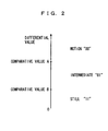
- Fig. 2 illustrates the relation between the frame-to-frame differential value of the composite video signal and motion and still states of the image.
- the image is determined as “still” if the differential value is less than a comparative value B, or determined as “motion” if the differential value is greater than a comparative value A. If the differential value is within the range from the comparative value A to the comparative value B, the image is determined as "intermediate” between "motion" and "still".
- the motion signal MS is "00” if the result of the determination is "motion”, while the motion signal MS is "11” if the result of the determination is “still”. If the result of the determination is "intermediate”, the motion signal MS is "01".
- the three-dimensional Y/C separation circuit 103 performs three-dimensional Y/C separation or two-dimensional Y/C separation on the composite video signal VD on the basis of the motion signal MS output from the motion detection circuit 102.
- video signals of adjacent two lines (scanning lines) or video signals of the same lines in continuous two frames have correlation, and chrominance signals superposed on the two video signals are of opposite phase with each other, or of 180 degrees out-of-phase. Therefore, a chrominance signal is extracted and a luminance signal is cancelled by performing subtraction on a composite video signal between adjacent lines, for example. Further, a chrominance signal is extracted and a luminance signal is cancelled by performing subtraction on a composite video signal between continuous frames, for example.
- the former method of separating a chrominance signal is referred to as two-dimensional Y/C separation
- the latter method of separating a chrominance signal is referred to as three-dimensional Y/C separation.
- the composite video signal VD is subjected to three-dimensional Y/C separation using an inter-frame operation.
- the chrominance signal is extracted by performing subtraction on the composite video signal VD and the output signal of the frame memory 101, and the luminance signal is extracted by subtracting the chrominance signal from the composite video signal VD.
- the composite video signal VD is subjected to two-dimensional Y/C separation using an inter-line operation.
- the chrominance signal is extracted by performing subtraction on a composite video signal VD of an adjacent line, and the luminance signal is extracted by subtracting the chrominance signal from the composite video signal VD.
- the motion signal MS output from the motion detection circuit 102 indicates "intermediate"
- the weighted mean of a luminance signal obtained by three-dimensional Y/C separation using an inter-frame operation and a luminance signal obtained by two-dimensional Y/C separation using an inter-line operation is found, and the weighted mean of a chrominance signal obtained by three-dimensional Y/C separation using an inter-frame operation and a chrominance signal obtained by two-dimensional Y/C separation using an inter-line operation is found.
- the luminance signal Y1 and the chrominance signal C1 are separated from the composite video signal VD.
- three-dimensional Y/C separation is performed using an inter-frame operation thereby improving the S/N.
- two-dimensional Y/C separation is performed using an intra-frame operation.
- the frame memory 105 delays the luminance signal Y1 output from the three-dimensional Y/C separation circuit 103 by one frame period. Further, the three-dimensional noise reduction circuit 105 performs three-dimensional noise reduction or two-dimensional noise reduction on the luminance signal Y1 output from the three-dimensional Y/C separation circuit 103 on the basis of the motion signal MS.
- the luminance signal Y1 is subjected to three-dimensional noise reduction using an inter-frame operation.
- the weighted mean of the luminance signal Y1 and the output signal of the frame memory 105 is found by the three-dimensional noise reduction, and the result is output as a luminance signal Y2.
- the luminance signal Y1 is subjected to two-dimensional noise reduction using an intra-frame operation.
- the luminance signal Y1 is directly output as the luminance signal Y2, by the two-dimensional noise reduction.
- the motion signal MS output from the motion detection circuit 102 indicates "intermediate"
- the weighted mean of a luminance signal obtained by three-dimensional noise reduction using an inter-frame operation and a luminance signal obtained by two-dimensional noise reduction using an intra-frame operation is found and the result is output as the luminance signal Y2.
- the three-dimensional noise reduction circuit 106 directly outputs the chrominance signal C1 as a chrominance signal C2.
- noise is reduced by three-dimensional noise reduction using an inter-frame operation.
- noise is reduced by two-dimensional noise reduction using an intra-frame operation.
- the video signal processing circuit employs the motion detection circuit 102 in common for the three-dimensional Y/C separation circuit 103 and the three-dimensional noise reduction circuit 106, whereby motion of the image is smoothed, the degree of integration can be improved and the cost can be reduced.
- noise is reduced in the three-dimensional Y/C separation circuit 103 and the three-dimensional noise reduction circuit 106, whereby the S/N is further improved and higher picture quality is attained.
- An inter-line operation or coring may be performed as the two-dimensional reduction.
- Frame-cyclic noise reduction may be performed as the three-dimensional noise reduction.
- three-dimensional noise reduction or two-dimensional noise reduction is performed as to the separated luminance signal Y1 in this embodiment, three-dimensional noise reduction or two-dimensional noise reduction may be performed also as to the chrominance signal C1.
- Fig. 3 is a block diagram showing a video signal processing circuit according to a second embodiment of the present invention.
- the video signal processing circuit shown in Fig. 3 is different from that shown in Fig. 1 in a point that a motion detection circuit 107 and a synthesizing circuit 108 are additionally provided.
- a motion detection circuit 102 outputs a motion signal MS1.
- the motion signal MS1 is supplied to a three-dimensional Y/C separation circuit 103 and the synthesizing circuit 108.
- a luminance signal Y1 output from the three-dimensional Y/C separation circuit 103 is supplied to a frame memory 105 and the motion detection circuit 107.
- the frame memory 105 delays the luminance signal Y1 by one frame period.
- An output signal of the frame memory 105 is supplied to a three-dimensional noise reduction circuit 106 and the motion detection circuit 107.
- the motion detection circuit 107 detects presence/absence of motion in an image on the basis of the luminance signal Y1 output from the three-dimensional Y/C separation circuit 103 and the output signal of the frame memory 105, and outputs a motion signal MS2 indicating the result of the detection.
- the motion signal MS output from the motion detection circuit 107 is supplied to the synthesizing circuit 108.
- the synthesizing circuit 108 synthesizes the motion signal MS1 output from the motion detection circuit 102 and the motion signal MS2 output from the motion detection circuit 107.
- a synthetic signal MS3 output from the synthesizing circuit 108 is supplied to the three-dimensional noise reduction circuit 106.
- the remaining structure of the video signal processing circuit shown in Fig. 3 is similar to that of the video signal processing circuit shown in Fig. 1 .
- the three-dimensional Y/C separation circuit 103 corresponds to the separation circuit
- the three-dimensional noise reduction circuit 106 corresponds to the noise reduction circuit
- the motion detection circuit 102 corresponds to the first motion detection circuit
- the motion detection circuit 107 corresponds to the second motion detection circuit.
- the frame memory 101 corresponds to the first delay circuit
- the frame memory 105 corresponds to the second delay circuit
- the synthesizing circuit 108 corresponds to the synthesizing circuit.
- the frame memory 101 delays an input composite video signal VD by one frame period.
- the motion detection circuit 102 calculates the differential value between the composite video signal VD and the output signal of the frame memory 101, and outputs the motion signal MS1 responsive to the differential value.
- presence/absence of motion in the image is detected by the frame-to-frame difference of the composite video signal VD.
- the three-dimensional Y/C separation circuit 103 performs three-dimensional Y/C separation or two-dimensional Y/C separation on the composite video signal VD on the basis of the motion signal MS1 output from the motion detection circuit 102.
- the composite video signal VD is subjected to three-dimensional Y/C separation using an inter-frame operation.
- the chrominance signal is extracted by performing subtraction on the composite video signal VD and the output signal of the frame memory 101, and the luminance signal is extracted by subtracting the chrominance signal from the composite video signal VD.
- the composite video signal VD is subjected to two-dimensional Y/C separation using an inter-line operation.
- the chrominance signal is extracted by performing subtraction on a composite video signal VD of an adjacent line, and the luminance signal is extracted by subtracting the chrominance signal from the composite video signal VD.
- the motion signal MS1 output from the motion detection circuit 102 indicates "intermediate"
- the weighted mean of a luminance signal obtained by three-dimensional Y/C separation using an inter-frame operation and a luminance signal obtained by two-dimensional Y/C separation using an inter-line operation is found and the weighted mean of a chrominance signal obtained by three-dimensional Y/C separation using an inter-frame operation and a chrominance signal obtained by two-dimensional Y/C separation using an inter-line operation is found.
- the luminance signal Y1 and the chrominance signal C1 are separated from the composite video signal VD.
- three-dimensional Y/C separation is performed using an inter-frame operation, thereby improving the S/N.
- two-dimensional Y/C separation is performed using an intra-frame operation.
- the frame memory 105 delays the luminance signal Y1 output from the three-dimensional Y/C separation circuit 103 by one frame period.
- the motion detection circuit 107 calculates the differential value between the luminance signal Y1 output from the three-dimensional Y/C separation circuit 103 and the output signal of the frame memory 105, and outputs a motion signal MS2 responsive to the differential value.
- presence/absence of motion in the image is detected on the basis of frame-to-frame difference of the luminance signal Y1.
- the motion detection circuit 107 performs motion detection on the basis of the luminance signal Y1 separated from the composite video signal VD by the three-dimensional Y/C separation circuit 103 and improved in S/N, whereby a detection result of high precision can be obtained.
- the synthesizing circuit 108 synthesizes the motion signal MS1 output from the motion detection circuit 102 and the motion signal MS2 output from the motion detection circuit 107.
- the motion signals MS1 and MS2 can be synthesized by any logical operation such as a weighted mean operation, an OR operation or an AND operation.
- the synthetic signal MS3 output from the synthesizing circuit 108 indicates "motion" when at least one of the motion signals MS1 and MS2 indicates “motion", while otherwise indicating "still".
- the synthesizing circuit 108 is set in a motion priority mode.
- the three-dimensional noise reduction circuit 106 performs three-dimensional noise reduction or two-dimensional noise reduction on the luminance signal Y1 output from the three-dimensional Y/C separation circuit 103 on the basis of the synthetic signal MS3.
- the luminance signal Y1 is subjected to three-dimensional noise reduction using an inter-frame operation.
- the weighted mean of the luminance signal Y1 and the output signal of the frame memory 105 is found by the three-dimensional noise reduction, and the result is output as a luminance signal Y2.
- the luminance signal Y1 is subjected to two-dimensional noise reduction using an intra-frame operation.
- the luminance signal Y1 is directly output as the luminance signal Y2, by the two-dimensional noise reduction.
- the weighted mean of a luminance signal obtained by three-dimensional noise reduction using an inter-frame operation and a luminance signal obtained by two-dimensional noise reduction using an intra-frame operation is found and the result is output as the luminance signal Y2.
- the three-dimensional noise reduction circuit 106 directly outputs the chrominance signal C1 as the chrominance signal C2.
- noise is reduced by three-dimensional noise reduction using an inter-frame operation.
- noise is reduced by two-dimensional noise reduction using an intra-frame operation.
- the video signal processing circuit employs the motion detection circuit 102 in common for the three-dimensional Y/C separation circuit 103 and the three-dimensional noise reduction circuit 106, whereby motion of the image is smoothed, the degree of integration can be improved and the cost can be reduced.
- noise is reduced in the three-dimensional Y/C separation circuit 103 and the three-dimensional noise reduction circuit 106, whereby the S/N is further improved and higher picture quality is attained.
- the motion detection circuit 107 performs motion detection on the basis of the separated luminance signal Y1 and the three-dimensional noise reduction circuit 106 performs three-dimensional noise reduction or two-dimensional noise reduction on the basis of the synthetic signal MS3 of the motion signal MS1 and the motion signal MS2, whereby the precision of motion detection is improved and false detection is reduced. Consequently, the S/N is further improved, to attain higher picture quality.
- An inter-line operation or coring may be performed as the two-dimensional reduction.
- Frame-cyclic noise reduction may be performed as the three-dimensional noise reduction.
- three-dimensional noise reduction or two-dimensional noise reduction is performed as to the separated luminance signal Y1 in this embodiment, three-dimensional noise reduction or two-dimensional noise reduction may be performed also as to the chrominance signal C1.
- the synthesizing circuit 108 may be set in a still priority mode outputting a synthetic signal MS3 indicating "still” when at least one of the motion signals MS1 and MS2 indicates “still".
Landscapes
- Engineering & Computer Science (AREA)
- Multimedia (AREA)
- Signal Processing (AREA)
- Processing Of Color Television Signals (AREA)
- Picture Signal Circuits (AREA)
Claims (9)
- Circuit de traitement de signal vidéo comprenant:un circuit de détection agencé pour détecter la présence/absence de mouvement dans une image;un circuit de séparation agencé pour séparer un signal de luminance et un signal de chrominance d'un signal vidéo composite par une opération inter-trame ou une opération intra-trame sur la base du résultat de détection par ledit circuit de détection; etun premier circuit à retard agencé pour retarder ledit signal vidéo composite d'une ou de plusieurs périodes de balayage vertical, etun deuxième circuit à retard agencé pour retarder au moins ladite sortie de signal de luminance dudit circuit de séparation d'une ou de plusieurs périodes de balayage vertical, etun circuit de réduction de bruit agencé pour réduire le bruit d'au moins ledit signal de luminance émis par ledit circuit de séparation par une opération inter-trameou une opération intra-trame sur la base du résultat de détection par ledit circuit de détection;
où ledit circuit de détection comprend:un premier circuit de détection de mouvement agencé pour détecter la présence/absence de mouvement dans ladite image en opérant sur ledit signal vidéo composite et un signal de sortie dudit premier circuit à retard,un deuxième circuit de détection de mouvement agencé pour détecter la présence/absence de mouvement dans ladite image sur la base d'au moins ledit signal de luminance émis par ledit circuit de séparation et un signal de sortie dudit deuxième circuit à retard;un circuit de synthétisation agencé pour synthétiser des signaux de sortie dudit premier circuit de détection de mouvement et dudit deuxième circuit de détection de mouvement,et où:ledit circuit de séparation est agencé pour séparer ledit signal de luminance et ledit signal de chrominance dudit signal vidéo composite par une opération inter-trame
ou une opération intra-trame sur la base dudit signal de sortie dudit premier circuit de détection de mouvement et un signal de sortie dudit premier circuit à retard,ledit circuit de réduction de bruit est agencé pour réduire le bruit d'au moins ledit signal de luminance émis par ledit circuit de séparation par une opération inter-trame ou une opération intra-trame sur la base d'un signal de sortie dudit circuit de synthétisation et dudit signal de sortie dudit deuxième circuit à retard,ledit circuit de séparation est agencé pour exécuter une opération intra-trame lorsque ledit signal de sortie dudit premier circuit de détection de mouvement indique la présence d'un mouvement dans ladite image, et pour exécuter une opération inter-trame lorsque ledit signal de sortie dudit premier circuit de détection de mouvement indique l'absence de mouvement dans ladite image, etledit circuit de réduction de bruit est agencé pour exécuter une opération intra-trame ou pas d'opération lorsque ledit signal de sortie dudit circuit de synthétisation indique la présence de mouvement dans ladite image, et pour exécuter une opération inter-trame lorsque ledit signal de sortie dudit circuit de synthétisation indique l'absence de mouvement dans ladite image,ledit premier circuit de détection de mouvement est agencé pour calculer une valeur différentielle entre ledit signal vidéo composite et ledit signal de sortie dudit premier circuit à retard et pour détecter la présence/absence de mouvement dans ladite image sur la base de ladite valeur différentielle calculée,ledit deuxième circuit de détection de mouvement est agencé pour calculer une valeur différentielle entre au moins ledit signal de luminance émis par ledit circuit de séparation et ledit signal de sortie dudit deuxième circuit à retard et pour détecter la présence/absence de mouvement dans ladite image sur la base de ladite valeur différentielle calculée,ledit premier circuit de détection de mouvement est agencé pour déterminer que ladite image a du mouvement lorsque ladite valeur différentielle calculée est supérieure à une valeur prescrite, et pour déterminer que ladite image n'a pas de mouvement lorsque ladite valeur différentielle calculée n'est pas plus grande que ladite valeur prescrite, etledit deuxième circuit de détection de mouvement est agencé pour déterminer que ladite image a du mouvement lorsque ladite valeur différentielle calculée est supérieure à une valeur prescrite, et pour déterminer que ladite image n'a pas de mouvement lorsque ladite valeur différentielle calculée n'est pas supérieure à ladite valeur prescrite,ledit premier circuit de détection de mouvement est agencé pour déterminer que ladite image n'a pas de mouvement lorsque ladite valeur différentielle calculée est plus grande qu'une première valeur calculée, pour déterminer que ladite image n'a pas de mouvement lorsque ladite valeur différentielle calculée est plus petite qu'une deuxième valeur, et pour déterminer que le mouvement dans ladite image est dans un état intermédiaire lorsque ladite valeur différentielle calculée se situe dans la plage de ladite première valeur à ladite deuxième valeur, etledit deuxième circuit de détection de mouvement est agencé pour déterminer que ladite image a du mouvement lorsque ladite valeur différentielle est plus grande qu'une troisième valeur, pour déterminer que ladite image n'a pas de mouvement lorsque ladite valeur différentielle est plus petite qu'une quatrième valeur, et pour déterminer que le mouvement dans ladite image est dans un état intermédiaire lorsque ladite valeur différentielle est dans la plage de ladite troisième valeur à ladite quatrième valeur. - Circuit de traitement de signal vidéo selon la revendication 1, où
ledit circuit de séparation exécute une opération employant un résultat d'une opération intra-trame et un résultat d'une opération inter-trame lorsque ledit premier circuit de détection de mouvement détermine que le mouvement dans ladite image est dans ledit état intermédiaire, et
ledit circuit de réduction de bruit exécute une opération employant un résultat d'une opération intra-trame et un résultat d'une opération inter-trame lorsque ledit deuxième circuit de détection de mouvement détermine que le mouvement dans ladite image est dans ledit état intermédiaire. - Circuit de traitement de signal vidéo selon la revendication 1, où
ledit circuit de séparation sépare ledit signal de luminance et ledit signal de chrominance dudit signal vidéo composite par une opération utilisant des signaux vidéo composites de deux lignes adjacentes comme ladite opération intra-trame lorsque ledit circuit de détection détecte la présence de mouvement dans ladite image, et sépare ledit signal de luminance et ledit signal de chrominance dudit signal vidéo composite par une opération utilisant des signaux vidéo composites des mêmes lignes dans deux trames continues comme opération inter-trame précitée lorsque ledit circuit de détection détecte l'absence de mouvement dans ladite image. - Circuit de traitement de signal vidéo selon la revendication 1, où
ledit circuit de réduction de bruit exécute une opération utilisant au moins des signaux de luminance de deux lignes adjacentes comme ladite opération intra-trame ou n'exécute pas d'opération lorsque ledit circuit de détection détecte la présence de mouvement dans ladite image, et exécute une opération utilisant au moins des signaux de luminance des mêmes lignes dans deux trames continues comme ladite opération inter-trame lorsque ledit circuit de détection détecte l'absence de mouvement dans ladite image. - Circuit de traitement de signal vidéo selon la revendication 1, où
ledit circuit de séparation comprend un circuit de séparation tridimensionnel Y/C, et ledit circuit de réduction de bruit comprend un circuit de réduction de bruit tridimensionnel. - Procédé de traitement d'un signal vidéo comprenant les étapes de:détecter une présence/absence de mouvement dans une image;séparer un signal de luminance et un signal de chrominance d'un signal vidéo composite par une opération inter-trame ou une opération intra-trame sur la base du résultat de ladite étape de détection; etretarder ledit signal vidéo composite d'une ou de plusieurs périodes de balayage vertical, et retarder au moins ledit signal de luminance émis par ledit circuit de séparation d'une ou de plusieurs périodes de balayage vertical, etréduire le bruit d'au moins ledit signal de luminance émis par ledit circuit de séparation par une opération inter-trame ou une opération intra-trame sur la base du résultat de détection par ledit circuit de détection;où ladite étape de détection comprend:une première étape de détection détectant la présence/absence de mouvement dans ladite image en opérant sur ledit signal vidéo composite et un signal de sortie produit pour ledit retardement dudit signal vidéo composite,une deuxième étape de détection détectant la présence/absence de mouvement dans ladite image sur la base d'au moins ledit signal de luminance et un signal de sortie produit par ledit retardement dudit signal de luminance,l'étape de synthétisation des signaux de sortie desdites première et deuxième étapes de détection, et où:ledit signal de luminance et ledit signal de chrominance sont séparés dudit signal vidéo composite par une opération inter-trame ou une opération intra-trame sur la base desdits signaux de sortie desdites premières étapes de détection et le signal de sortie produit par le retardement du signal vidéo composite réduit le bruit d'au moins ledit signal de luminance émis par une opération inter-trame ou une opération intra-trame sur la base d'un signal de sortie de ladite étape de synthétisation et dudit signal de sortie produit par ledit retardement du signal de luminance,une opération intra-trame est exécutée lorsque ledit signal de sortie de ladite première étape de détection indique la présence de mouvement dans ladite image, et une opération inter-trame est exécutée lorsque ledit signal de sortie de ladite première étape de détection indique l'absence de mouvement dans ladite image, etune opération intra-trame ou pas d'opération est exécutée lorsque ledit signal de sortie de ladite étape de synthétisation indique la présence de mouvement dans ladite image, et une opération inter-trame est exécutée lorsque ledit signal de sortie de ladite étape de synthétisation indique l'absence de mouvement dans ladite image,ladite première étape de détection implique le calcul d'une valeur différentielle entre ledit signal vidéo composite et ledit signal de sortie produit par ledit retardement dudit signal vidéo composite et la détection de la présence/absence de mouvement dans ladite image sur la base de ladite valeur différentielle calculée,ladite deuxième étape de détection impliquée est agencée pour calculer une valeur différentielle entre au moins ledit signal de luminance émis par ladite étape de séparation et ledit signal de sortie produit par ledit retardement dudit signal de luminance et la détection de la présence/absence de mouvement dans ladite image sur la base de ladite valeur différentielle calculée,ladite première étape de détection détermine que ladite image a du mouvement lorsque ladite valeur différentielle calculée est supérieure à une valeur prescrite et détermine que ladite image n'a pas de mouvement lorsque ladite valeur différentielle calculée n'est pas supérieure à ladite valeur prescrite, etladite deuxième étape de détection détermine que ladite image a du mouvement lorsque ladite valeur différentielle calculée est supérieure à une valeur prescrite, et détermine que ladite image n'a pas de mouvement lorsque ladite valeur différentielle calculée n'est pas supérieure à ladite valeur prescrite,ladite première étape de détection détermine que ladite image n'a pas de mouvement lorsque ladite valeur différentielle calculée est supérieure à une première valeur, détermine que ladite image n'a pas de mouvement lorsque ladite valeur différentielle calculée est inférieure à une deuxième valeur et détermine que le mouvement dans ladite image est dans un état intermédiaire lorsque ladite valeur différentielle calculée est dans la plage de ladite première valeur à ladite deuxième valeur, etladite deuxième étape de détection détermine que ladite image a du mouvement lorsque ladite valeur différentielle est supérieure à une troisième valeur, détermine que ladite image n'a pas de mouvement lorsque ladite valeur différentielle est inférieure à une quatrième valeur et détermine que le mouvement dans ladite image est dans un état intermédiaire lorsque ladite valeur différentielle est dans la plage de ladite troisième valeur à ladite quatrième valeur.
- Procédé selon la revendication 6, incluant l'exécution d'une opération employant un résultat d'une opération intra-trame et un résultat d'une opération inter-trame lorsque ladite première étape de détection détermine que le mouvement dans ladite image est dans ledit état intermédiaire, et
exécuter une opération employant un résultat d'une opération intra-trame et un résultat d'une opération inter-trame lorsque ladite deuxième étape de détection détermine que le mouvement dans ladite image est dans ledit état intermédiaire. - Procédé selon la revendication 6, incluant la séparation dudit signal de luminance et dudit signal de chrominance dudit signal vidéo composite par une opération utilisant des signaux vidéo composites de deux lignes adjacentes comme ladite opération intra-trame lorsque la présence de mouvement est détectée dans ladite image, et la séparation dudit signal de luminance et dudit signal de chrominance dudit signal vidéo composite par une opération utilisant des signaux vidéo composites des mêmes lignes dans deux trames continues comme ladite opération inter-trame lorsqu'une absence de mouvement dans ladite image est détectée.
- Procédé selon la revendication 6, incluant l'exécution d'une opération utilisant au moins des signaux de luminance de deux lignes adjacentes comme ladite opération intra-trame ou pas d'exécution d'opération lorsqu'une présence de mouvement dans ladite image est détectée, et l'exécution d'une opération utilisant au moins les signaux de luminance des mêmes lignes dans deux trames continues comme ladite opération inter-trame lorsqu'une absence de mouvement dans ladite image est détectée.
Applications Claiming Priority (2)
| Application Number | Priority Date | Filing Date | Title |
|---|---|---|---|
| JP20159098A JP4061721B2 (ja) | 1998-07-16 | 1998-07-16 | 映像信号処理回路および映像信号処理方法 |
| JP20159098 | 1998-07-16 |
Publications (3)
| Publication Number | Publication Date |
|---|---|
| EP0973341A2 EP0973341A2 (fr) | 2000-01-19 |
| EP0973341A3 EP0973341A3 (fr) | 2001-10-10 |
| EP0973341B1 true EP0973341B1 (fr) | 2009-09-16 |
Family
ID=16443587
Family Applications (1)
| Application Number | Title | Priority Date | Filing Date |
|---|---|---|---|
| EP99305610A Expired - Lifetime EP0973341B1 (fr) | 1998-07-16 | 1999-07-15 | Procédé et circuit de traitement de signal vidéo |
Country Status (6)
| Country | Link |
|---|---|
| US (1) | US6400762B2 (fr) |
| EP (1) | EP0973341B1 (fr) |
| JP (1) | JP4061721B2 (fr) |
| DE (1) | DE69941417D1 (fr) |
| MY (1) | MY126470A (fr) |
| TW (1) | TW437238B (fr) |
Families Citing this family (20)
| Publication number | Priority date | Publication date | Assignee | Title |
|---|---|---|---|---|
| KR100407952B1 (ko) * | 2001-05-09 | 2003-12-03 | 엘지전자 주식회사 | 색/휘도 신호 분리회로 및 분리방법 |
| TWI232060B (en) * | 2003-12-22 | 2005-05-01 | Sunplus Technology Co Ltd | A method of inter-frame Y/C separation |
| TWI227630B (en) * | 2003-12-22 | 2005-02-01 | Sunplus Technology Co Ltd | A method of inter-frame Y/C separation |
| TWI229556B (en) * | 2003-12-22 | 2005-03-11 | Sunplus Technology Co Ltd | Method of motion detection for 3D comb filter video decoder |
| TWI228935B (en) * | 2003-12-22 | 2005-03-01 | Sunplus Technology Co Ltd | Method of motion detection for 3D comb filter video decoder |
| JP3801179B2 (ja) * | 2004-01-30 | 2006-07-26 | 松下電器産業株式会社 | フレーム巡回型ノイズ低減方法 |
| JP4417780B2 (ja) * | 2004-05-31 | 2010-02-17 | 株式会社東芝 | ノイズ除去装置及び画像表示装置 |
| JP2006033739A (ja) * | 2004-07-21 | 2006-02-02 | Toshiba Corp | 電子機器、映像データ受信方法および映像データ受信装置 |
| JP4861636B2 (ja) * | 2005-04-19 | 2012-01-25 | パナソニック株式会社 | 画像処理装置及び画像処理プログラム |
| US7522214B1 (en) | 2005-06-27 | 2009-04-21 | Magnum Semiconductor, Inc. | Circuits and methods for deinterlacing video display data and systems using the same |
| US7450184B1 (en) | 2005-06-27 | 2008-11-11 | Magnum Semiconductor, Inc. | Circuits and methods for detecting 2:2 encoded video and systems utilizing the same |
| US7414671B1 (en) | 2005-06-30 | 2008-08-19 | Magnum Semiconductor, Inc. | Systems and methods for display object edge detection and pixel data interpolation in video processing systems |
| TWI311436B (en) * | 2005-07-05 | 2009-06-21 | Realtek Semiconductor Corp | Motion detection method |
| US7538824B1 (en) | 2005-08-18 | 2009-05-26 | Magnum Semiconductor, Inc. | Systems and methods for reducing noise during video deinterlacing |
| TWI401944B (zh) * | 2007-06-13 | 2013-07-11 | Novatek Microelectronics Corp | 用於視訊處理系統之雜訊消除裝置 |
| JP2009044450A (ja) * | 2007-08-08 | 2009-02-26 | Toshiba Microelectronics Corp | 3次元y/c分離回路 |
| JP2009100373A (ja) * | 2007-10-18 | 2009-05-07 | Sanyo Electric Co Ltd | ノイズ低減処理装置、ノイズ低減処理方法、及び電子機器 |
| JP5645699B2 (ja) * | 2011-02-16 | 2014-12-24 | 三菱電機株式会社 | 動き検出装置及び方法、映像信号処理装置及び方法、並びに映像表示装置 |
| WO2013147756A1 (fr) * | 2012-03-28 | 2013-10-03 | Intel Corporation | Ajustement sélectif en fonction du contenu d'une estimation du mouvement |
| US9269158B2 (en) | 2012-09-25 | 2016-02-23 | Nokia Technologies Oy | Method, apparatus and computer program product for periodic motion detection in multimedia content |
Family Cites Families (13)
| Publication number | Priority date | Publication date | Assignee | Title |
|---|---|---|---|---|
| JPS5510228A (en) * | 1978-07-05 | 1980-01-24 | Nec Corp | S/n improving unit for television video signal |
| US4658285A (en) * | 1985-09-30 | 1987-04-14 | Rca Corporation | Video signal noise reduction apparatus |
| JPH0213088A (ja) * | 1988-06-30 | 1990-01-17 | Nec Home Electron Ltd | 複合映像信号のy/c分離装置 |
| JPH0229178A (ja) * | 1988-07-19 | 1990-01-31 | Sony Corp | 映像信号処理回路 |
| JPH07110049B2 (ja) | 1989-01-10 | 1995-11-22 | 日本電気株式会社 | ノイズリダクション回路 |
| US5475445A (en) * | 1990-04-03 | 1995-12-12 | Mitsubishi Denki Kabushiki Kaisha | Motion adaptive luminance signal and color signal separation filter |
| JP2950632B2 (ja) * | 1991-03-26 | 1999-09-20 | 株式会社東芝 | 超音波診断装置 |
| JPH04328988A (ja) * | 1991-04-30 | 1992-11-17 | Toshiba Corp | 映像信号処理装置 |
| JP3144860B2 (ja) * | 1991-12-10 | 2001-03-12 | 株式会社東芝 | 映像信号処理装置 |
| JPH07110049A (ja) | 1993-03-29 | 1995-04-25 | Aichi Pref Gov | 機械の支持方法及びそのための架台 |
| JPH0787519A (ja) * | 1993-09-16 | 1995-03-31 | Toshiba Corp | 輝度信号・色信号分離回路 |
| JPH0846992A (ja) * | 1994-08-02 | 1996-02-16 | Toshiba Corp | 動き適応3次元信号処理装置 |
| KR100202565B1 (ko) * | 1996-03-23 | 1999-06-15 | 구자홍 | 복합영상신호의 3차원 휘도/색신호 분리 장치 |
-
1998
- 1998-07-16 JP JP20159098A patent/JP4061721B2/ja not_active Expired - Fee Related
-
1999
- 1999-07-12 TW TW088111799A patent/TW437238B/zh not_active IP Right Cessation
- 1999-07-14 MY MYPI99002981A patent/MY126470A/en unknown
- 1999-07-15 US US09/353,924 patent/US6400762B2/en not_active Expired - Fee Related
- 1999-07-15 DE DE69941417T patent/DE69941417D1/de not_active Expired - Fee Related
- 1999-07-15 EP EP99305610A patent/EP0973341B1/fr not_active Expired - Lifetime
Also Published As
| Publication number | Publication date |
|---|---|
| EP0973341A3 (fr) | 2001-10-10 |
| JP4061721B2 (ja) | 2008-03-19 |
| TW437238B (en) | 2001-05-28 |
| JP2000032494A (ja) | 2000-01-28 |
| US6400762B2 (en) | 2002-06-04 |
| US20010050956A1 (en) | 2001-12-13 |
| EP0973341A2 (fr) | 2000-01-19 |
| DE69941417D1 (de) | 2009-10-29 |
| MY126470A (en) | 2006-10-31 |
Similar Documents
| Publication | Publication Date | Title |
|---|---|---|
| EP0973341A2 (fr) | Procédé et circuit de traitement de signal vidéo | |
| US4891701A (en) | Television signal frame number converter capable of determining an optimum interpolation coefficient | |
| US8559517B2 (en) | Image processing apparatus and image display apparatus provided with the same | |
| US4768092A (en) | Image signal conversion device | |
| JP2005051460A (ja) | ビデオ信号処理装置及びビデオ信号の処理方法 | |
| US7961961B2 (en) | Image processing apparatus and image processing program using motion information | |
| JPH03190473A (ja) | ビデオ信号処理装置 | |
| JP3359439B2 (ja) | ノイズ低減回路 | |
| US4984070A (en) | Picture quality improving apparatus capable of reducing deterioration of interpolated signal | |
| JP3149677B2 (ja) | Y/c分離装置 | |
| US8199256B2 (en) | Three-dimensional Y/C separating circuit | |
| JP3350322B2 (ja) | 映像信号処理装置 | |
| JP2602213B2 (ja) | テレビジヨン受像機 | |
| JP3365127B2 (ja) | 動き検出装置 | |
| JPH05336497A (ja) | 動き検出回路 | |
| JPH0123995B2 (fr) | ||
| JPS6225588A (ja) | 動きベクトル検出装置 | |
| JP4681288B2 (ja) | Y/c分離回路 | |
| JP2947132B2 (ja) | ベクトル検出装置 | |
| JPH05219531A (ja) | 動き信号発生回路 | |
| JP2558087B2 (ja) | 動き部分検出方法 | |
| JPH0389790A (ja) | 動き情報検出回路 | |
| JP2776122B2 (ja) | 動き検出方式 | |
| JPH0715745A (ja) | 動き検出回路 | |
| JP2733175B2 (ja) | 複合映像信号の相関検出装置 |
Legal Events
| Date | Code | Title | Description |
|---|---|---|---|
| PUAI | Public reference made under article 153(3) epc to a published international application that has entered the european phase |
Free format text: ORIGINAL CODE: 0009012 |
|
| AK | Designated contracting states |
Kind code of ref document: A2 Designated state(s): AT BE CH CY DE DK ES FI FR GB GR IE IT LI LU MC NL PT SE Kind code of ref document: A2 Designated state(s): DE FR GB |
|
| AX | Request for extension of the european patent |
Free format text: AL;LT;LV;MK;RO;SI |
|
| PUAL | Search report despatched |
Free format text: ORIGINAL CODE: 0009013 |
|
| AK | Designated contracting states |
Kind code of ref document: A3 Designated state(s): AT BE CH CY DE DK ES FI FR GB GR IE IT LI LU MC NL PT SE |
|
| AX | Request for extension of the european patent |
Free format text: AL;LT;LV;MK;RO;SI |
|
| RIC1 | Information provided on ipc code assigned before grant |
Free format text: 7H 04N 9/64 A, 7H 04N 5/21 B, 7H 04N 9/78 B |
|
| 17P | Request for examination filed |
Effective date: 20020313 |
|
| AKX | Designation fees paid |
Free format text: DE FR GB |
|
| 17Q | First examination report despatched |
Effective date: 20061117 |
|
| RAP1 | Party data changed (applicant data changed or rights of an application transferred) |
Owner name: PANASONIC CORPORATION |
|
| GRAP | Despatch of communication of intention to grant a patent |
Free format text: ORIGINAL CODE: EPIDOSNIGR1 |
|
| GRAS | Grant fee paid |
Free format text: ORIGINAL CODE: EPIDOSNIGR3 |
|
| GRAA | (expected) grant |
Free format text: ORIGINAL CODE: 0009210 |
|
| AK | Designated contracting states |
Kind code of ref document: B1 Designated state(s): DE FR GB |
|
| REG | Reference to a national code |
Ref country code: GB Ref legal event code: FG4D |
|
| REF | Corresponds to: |
Ref document number: 69941417 Country of ref document: DE Date of ref document: 20091029 Kind code of ref document: P |
|
| PLBE | No opposition filed within time limit |
Free format text: ORIGINAL CODE: 0009261 |
|
| STAA | Information on the status of an ep patent application or granted ep patent |
Free format text: STATUS: NO OPPOSITION FILED WITHIN TIME LIMIT |
|
| 26N | No opposition filed |
Effective date: 20100617 |
|
| PGFP | Annual fee paid to national office [announced via postgrant information from national office to epo] |
Ref country code: GB Payment date: 20100714 Year of fee payment: 12 |
|
| REG | Reference to a national code |
Ref country code: FR Ref legal event code: ST Effective date: 20110331 |
|
| PG25 | Lapsed in a contracting state [announced via postgrant information from national office to epo] |
Ref country code: DE Free format text: LAPSE BECAUSE OF NON-PAYMENT OF DUE FEES Effective date: 20110201 |
|
| REG | Reference to a national code |
Ref country code: DE Ref legal event code: R119 Ref document number: 69941417 Country of ref document: DE Effective date: 20110201 |
|
| PG25 | Lapsed in a contracting state [announced via postgrant information from national office to epo] |
Ref country code: FR Free format text: LAPSE BECAUSE OF NON-PAYMENT OF DUE FEES Effective date: 20100802 |
|
| GBPC | Gb: european patent ceased through non-payment of renewal fee |
Effective date: 20110715 |
|
| PG25 | Lapsed in a contracting state [announced via postgrant information from national office to epo] |
Ref country code: GB Free format text: LAPSE BECAUSE OF NON-PAYMENT OF DUE FEES Effective date: 20110715 |