EP0973673B1 - Substructure de châssis à écartement variable pour pose de voies ferrées - Google Patents
Substructure de châssis à écartement variable pour pose de voies ferrées Download PDFInfo
- Publication number
- EP0973673B1 EP0973673B1 EP97919333A EP97919333A EP0973673B1 EP 0973673 B1 EP0973673 B1 EP 0973673B1 EP 97919333 A EP97919333 A EP 97919333A EP 97919333 A EP97919333 A EP 97919333A EP 0973673 B1 EP0973673 B1 EP 0973673B1
- Authority
- EP
- European Patent Office
- Prior art keywords
- frames
- central frame
- sub
- undercarriage
- control
- Prior art date
- Legal status (The legal status is an assumption and is not a legal conclusion. Google has not performed a legal analysis and makes no representation as to the accuracy of the status listed.)
- Expired - Lifetime
Links
- 230000008878 coupling Effects 0.000 claims description 4
- 238000010168 coupling process Methods 0.000 claims description 4
- 238000005859 coupling reaction Methods 0.000 claims description 4
- 230000000295 complement effect Effects 0.000 claims description 2
- 230000008901 benefit Effects 0.000 description 3
- 230000002452 interceptive effect Effects 0.000 description 2
- 230000004913 activation Effects 0.000 description 1
- 230000015572 biosynthetic process Effects 0.000 description 1
- 230000015556 catabolic process Effects 0.000 description 1
- 238000012423 maintenance Methods 0.000 description 1
- 230000004048 modification Effects 0.000 description 1
- 238000012986 modification Methods 0.000 description 1
- 230000009467 reduction Effects 0.000 description 1
Images
Classifications
-
- B—PERFORMING OPERATIONS; TRANSPORTING
- B62—LAND VEHICLES FOR TRAVELLING OTHERWISE THAN ON RAILS
- B62D—MOTOR VEHICLES; TRAILERS
- B62D55/00—Endless track vehicles
- B62D55/08—Endless track units; Parts thereof
- B62D55/084—Endless-track units or carriages mounted separably, adjustably or extensibly on vehicles, e.g. portable track units
Definitions
- the invention relates to a variable-gauge undercarriage according to the preamble of claim 1.
- Such track-laying undercarriages are present on the market.
- Document FR-A-2 249 545 discloses an undercarriage with hydraulic variation of the gauge.
- This known undercarriage which is devised for application to a tracked hydraulic shovel, has an H-shaped central frame and two lateral sub-frames.
- the central frame has tubular ends, and the sub-frames have tubular side arms in which the ends of the central frame are telescopically slidable.
- the object of the present invention is to eliminate the disadvantages of the known prior art.
- the invention as characterised by the claims solves the problem of use of a very stable structure with large telescopic movements while being localised solely on the track-laying structures.
- An integrated structural solution is thus provided in which all the components for varying the gauge of the undercarriage are within the supporting structure and distributed symmetrically so as not to destabilise the machine in use.
- safe, simple, remote guide systems are used, with the introduction of negative-type controls which operate in the case of damage to or breakdown of parts of the plant.
- the appendages have outer portions which are longer than their inner portions, they can house respective longer portions of the ends of the central frame while simultaneously avoiding these projecting and interfering with the central body of the frame when the gauge is reduced.
- the appendages of the slide frames are shaped internally with prismatic guides for providing constant support for the ends of the frame.
- the central frame of the undercarriage contains hydraulic telescopic cylinders within its ends for adjusting the width of the gauge.
- An advantage achieved by the invention lies essentially in the fact that, during the operation needed to vary the gauge, the attitude of the machine is not varied.
- the manner in which the invention is achieved also allows extremely rapid dismantling of the parts.
- the telescopic cylinders are rapidly releasable and removable, as are also the lateral structures, without any need to act on the structural parts, which is particularly advantageous during transport or maintenance.
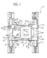
- a variable-gauge undercarriage suitable for a track-laying machine comprises a central H-frame 3 and two lateral sub-frames 2.
- the central frame 3 and the sub-frames 2 are irreleasably fixed together in correspondence with ends 5a, 5b of the central frame 3 and slide frames 7a, 7b of the sub-frames 2.
- the central frame 3 contains fluid-dynamic telescopic cylinders 4 for determining the width of the gauge.
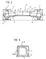
- the slide frames 7a, 7b of the sub-frames 2 have hollow coupling appendages 19 which are shaped externally so as to augment the movement between the maximum and minimum gauge widths and are shaped internally with prismatic guides having a bottom face 6 and a lateral face 9 ( Figures 3 to 5) for providing constant support for the ends 5a, 5b of the central frame 3.
- the appendages 19 have outer portions which are longer than their inner portions so that they can house respective longer portions of the ends 5a, 5b of the central frame 3 while simultaneously avoiding these projecting and interfering with the central body of the frame 3 when the gauge is reduced.
- each prismatic guide is formed with a bottom face 6 of the respective slide frames 7a, 7b, which provides vertical support for the respective end 5a, 5b of the central frame 3, and a lateral face 9 of the slide frames 7a, 7b complementary to a face 8 of the central frame 3 and adapted to provide lateral support for the latter.
- fluid-dynamic valves 32 are generally provided for controlling the operation of the telescopic cylinders 4. For maximum safety, only when a control which pressurises the cylinders 4 is given can these be actuated to vary the gauge. Often, however, a second safety system is provided; at each of the four points at which the central frame 3 is connected to the sub-frames 2, there may in fact be a second type of mechanical locking device 17 or 18 for locking the central frame 3 and the sub-frames 2 against relative movement in a position of use so as to provide further control of the geometric stability in use.
- This second system is again of the negative type, that is automatically engaged in the absence of a command which may be effected either by a remote control or manually.
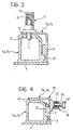
- Figures 3 and 4 illustrate these two solutions, respectively.
- the mechanical locking device 17, 18 includes a movable geometric-interference element 11, 20 which can move from a first, extended position, in which it interferes geometrically with the surfaces 12, 13, 21, 22 of the central frame 3 and the sub-frames 2, which are relatively movable therebetween, to a second, retracted position in which it does not interfere with these surfaces.
- a spring 15, 23 for controlling the position of the movable, geometric-interference element 11, 20 biases it towards the extended position in the absence of external inputs and a control 39, 24, able to overcome the force of the spring 15, 23, allows the retraction of the movable, geometric-interference element 11, 20.
- Figure 3 which shows the remote-control locking device 17, the movable, geometric-interference element 11 forms part of a fluid-dynamic cylinder 14 which also contains the spring 15 and, in the absence of pressure, maintains the movable, interference element 11 engaged with the relatively movable surfaces 12, 13, preventing their movement.
- the relative remote control 39 is shown in Figure 1 on the central frame 3 in a position accessible to the operator.
- the positioning of the movable interference element 20 effected by the manual control 24 causes the locking or unlocking of the facing surfaces 21, 22.
- the movable geometric-interference element 20 could be threaded and operated by a rotary control rather than a pull control, which shall in any case overcome the resistance of the spring 23.
Landscapes
- Engineering & Computer Science (AREA)
- Chemical & Material Sciences (AREA)
- Combustion & Propulsion (AREA)
- Transportation (AREA)
- Mechanical Engineering (AREA)
- Body Structure For Vehicles (AREA)
- Automatic Assembly (AREA)
- Component Parts Of Construction Machinery (AREA)
Claims (7)
- Substructure de châssis à écartement variable pour pose de voie ferrée, caractérisée par le fait de comprendre un cadre central (3) en forme de H et deux sous-cadres (2) latéraux, le cadre central (3) et les sous-cadres (2) étant fixés ensemble de façon indésolidarisable en correspondance avec des extrémités (5a, 5b) du cadre central (3) et avec des cadres de coulissement (7a, 7b) des sous-cadres (2), dans laquelle les cadres de coulissement (7a, 7b) des sous-cadres (2) ont des appendices d'accouplement (19) creux, dans laquelle les appendices d'accouplement (19) ont, par rapport à la direction de l'extension des sous-cadres (2), des parties extérieures qui sont plus longues que leurs parties intérieures opposées, et lesdits appendices d'accouplement (19) sont conformés intérieurement avec des guides prismatiques dont chacun est formé avec une face inférieure (6) du cadre de coulissement (7a, 7b) respectif, qui produit un support vertical pour l'extrémité (5a, 5b) respective du cadre central (3), et dans laquelle une face latérale (9) du cadre de coulissement (7a, 7b), à l'intérieur de la partie extérieure respective de chaque appendice, est complémentaire à une face (8) du cadre central (3) et adaptée pour fournir un support latéral pour ce dernier.
- Substructure selon la revendication 1, caractérisée en ce que le cadre central (3) contient des vérins hydrauliques (4) télescopiques à l'intérieur de ses extrémités (5a, 5b), afin d'ajuster la largeur de l'écartement.
- Substructure selon la revendication 1 ou 2, caractérisée en ce que, dans les cadres de coulissement (7a, 7b), elle comprend un dispositif de désolidarisation rapide et de fixation rapide (29) pour les vérins (4) télescopiques.
- Substructure selon la revendication 1 ou 2, caractérisée en ce qu'elle comprend un dispositif de verrouillage mécanique (17, 18) pour verrouiller le cadre central (3) par rapport aux sous-cadres (2) en une position d'utilisation, de manière à fournir une commande supplémentaire pour la stabilité géométrique, en utilisation.
- Substructure selon la revendication 4, caractérisée en ce que le dispositif de verrouillage mécanique (17, 18) comprend :un élément à interférence géométrique (11, 20) mobile, adapté pour se déplacer d'une première position, étendue, dans laquelle il interfère géométriquement avec les surfaces (12, 13, 21, 22), mobiles les unes par rapport aux autres, du cadre central (3) et des sous-cadres (2), en une deuxième position, rétractée, dans laquelle il n'interfère pas avec ces faces ;un ressort (15, 23) pour commander la position de l'élément à interférence géométrique (11, 20) mobile, afin de le maintenir dans sa position étendue ; etune commande (39, 24) pour surmonter la poussée du ressort (15, 23) et permettre la rétraction de l'élément à interférence géométrique (11, 20) mobile.
- Substructure selon la revendication 5, caractérisée en ce que la commande est une télécommande (39).
- Substructure selon la revendication 5, caractérisée en ce que la commande est une commande manuelle (24).
Applications Claiming Priority (1)
| Application Number | Priority Date | Filing Date | Title |
|---|---|---|---|
| PCT/EP1997/001805 WO1998046473A1 (fr) | 1997-04-11 | 1997-04-11 | Chassis de roulement a chenilles a ecartement variable |
Publications (2)
| Publication Number | Publication Date |
|---|---|
| EP0973673A1 EP0973673A1 (fr) | 2000-01-26 |
| EP0973673B1 true EP0973673B1 (fr) | 2003-03-19 |
Family
ID=8166583
Family Applications (1)
| Application Number | Title | Priority Date | Filing Date |
|---|---|---|---|
| EP97919333A Expired - Lifetime EP0973673B1 (fr) | 1997-04-11 | 1997-04-11 | Substructure de châssis à écartement variable pour pose de voies ferrées |
Country Status (4)
| Country | Link |
|---|---|
| EP (1) | EP0973673B1 (fr) |
| JP (1) | JP3954113B2 (fr) |
| DE (1) | DE69720067T2 (fr) |
| WO (1) | WO1998046473A1 (fr) |
Cited By (1)
| Publication number | Priority date | Publication date | Assignee | Title |
|---|---|---|---|---|
| EP1580101A3 (fr) * | 2004-03-26 | 2007-04-18 | B. Teupen Maschinenbau GmbH | Châssis d'un véhicule, le châssis étant adaptable à l'inclinaison du terrain |
Families Citing this family (8)
| Publication number | Priority date | Publication date | Assignee | Title |
|---|---|---|---|---|
| DE102006042771B4 (de) * | 2006-09-12 | 2014-01-16 | Kögel Trailer GmbH & Co. KG | Fahrzeugrahmen und Verfahren zur Herstellung eines derartigen Fahrzeugrahmens |
| DE102006053683A1 (de) | 2006-11-13 | 2008-05-15 | Horsch Maschinen Gmbh | Fahrgestell mit Rädern oder Raupenlaufwerk |
| RU2488509C2 (ru) | 2008-12-19 | 2013-07-27 | Катерпиллар Коммёршл С.А.Р.Л. | Аппарат фиксирующий для ходовой тележки с переменной колеей |
| CN202193135U (zh) * | 2011-08-23 | 2012-04-18 | 三一重机有限公司 | 履带式底盘伸缩机构及履带式桩工机械 |
| CN102874334A (zh) * | 2012-09-24 | 2013-01-16 | 玉柴桩工(常州)有限公司 | 履带底盘轨距调节机构 |
| DE202020101133U1 (de) * | 2020-03-02 | 2021-06-04 | Liebherr-Werk Nenzing Gmbh | Unterwagen für eine Arbeitsmaschine |
| CN111874115B (zh) * | 2020-07-22 | 2022-09-16 | 柳州柳工挖掘机有限公司 | 变轨行走架及工程机械 |
| CN116135772A (zh) * | 2023-04-20 | 2023-05-19 | 杭州尚研机械制造有限公司 | 一种大型履带式可伸缩式起重机底盘及其加工方法 |
Family Cites Families (4)
| Publication number | Priority date | Publication date | Assignee | Title |
|---|---|---|---|---|
| US3712398A (en) * | 1970-03-19 | 1973-01-23 | Orenstein & Koppel Ag | Hydraulically operable device for changing the track width of track-laying vehicles |
| US3820616A (en) * | 1972-02-03 | 1974-06-28 | American Hoist & Derrick Co | Crawler vehicle with dual extensible side frames |
| FR2249545A5 (fr) * | 1973-10-25 | 1975-05-23 | Poclain Sa | |
| FR2416825A1 (fr) * | 1978-02-09 | 1979-09-07 | Yumbo | Chassis de vehicule a chenilles a voie variable |
-
1997
- 1997-04-11 WO PCT/EP1997/001805 patent/WO1998046473A1/fr not_active Ceased
- 1997-04-11 DE DE69720067T patent/DE69720067T2/de not_active Expired - Fee Related
- 1997-04-11 JP JP54338898A patent/JP3954113B2/ja not_active Expired - Lifetime
- 1997-04-11 EP EP97919333A patent/EP0973673B1/fr not_active Expired - Lifetime
Cited By (1)
| Publication number | Priority date | Publication date | Assignee | Title |
|---|---|---|---|---|
| EP1580101A3 (fr) * | 2004-03-26 | 2007-04-18 | B. Teupen Maschinenbau GmbH | Châssis d'un véhicule, le châssis étant adaptable à l'inclinaison du terrain |
Also Published As
| Publication number | Publication date |
|---|---|
| EP0973673A1 (fr) | 2000-01-26 |
| JP3954113B2 (ja) | 2007-08-08 |
| WO1998046473A1 (fr) | 1998-10-22 |
| DE69720067T2 (de) | 2004-01-29 |
| DE69720067D1 (de) | 2003-04-24 |
| JP2001518859A (ja) | 2001-10-16 |
Similar Documents
| Publication | Publication Date | Title |
|---|---|---|
| EP0883543B1 (fr) | Appareil de verrouillage des parties mobiles d'un ecartement variable | |
| DE69428036T2 (de) | Rad blockierung | |
| DE69713877T2 (de) | Anti-kriech vorrichtung für anhänger mit luftfedern | |
| US5598896A (en) | Variable gage undercarriage arrangement | |
| DE68906235T2 (de) | Kran zum Heben und Aussetzen von Booten auf einem Kai bzw. von einem Kai. | |
| EP0973673B1 (fr) | Substructure de châssis à écartement variable pour pose de voies ferrées | |
| DE60020447T2 (de) | Fahrzeughebevorrichtung | |
| DE60215537T2 (de) | Unterfahrschutzvorrichtung | |
| US3945666A (en) | Powered outrigger beams having stabilizing spacer pad means | |
| DE2625632C3 (de) | Vorrichtung für die Übernahme, Ausrichtung und Montage einer Schiffsschraube und eines Steuerruders | |
| EP0309706B1 (fr) | Tracteur de piste pour avion avec un dispositif serre-flanc | |
| US3958813A (en) | Positive safety locking system for powered outrigger beams | |
| US4418625A (en) | Bidirectionally operative tie exchanging apparatus | |
| EP3440004B1 (fr) | Grue mobile munie d'un logement de lest et procédé de lestage d'une grue mobile | |
| DE3027518C2 (fr) | ||
| WO2020030521A1 (fr) | Système de grue automotrice pour le transport d'une pièce de montage, en particulier d'une flèche principale d'une grue automotrice | |
| DE19610374A1 (de) | Automatische Sicherung von Containern auf Ladeflächen | |
| US4421034A (en) | Compact bidirectionally operative tie exchanging apparatus | |
| DE69001396T2 (de) | Schlepparm mit selbstpositionierendem Gelenkhaken und damit ausgerüstetes Fahrzeug. | |
| DE102020108472A1 (de) | Anbaudrehpflug | |
| EP0333066B1 (fr) | Engin de terrassement, notamment un chargeur | |
| EP0806133A1 (fr) | Dispositif pour pivoter les roues râteleuses d'une machine de fenaison | |
| DE2154631B2 (de) | Ueberlastungsschutzvorrichtung fuer einen ladekran | |
| US4229019A (en) | Transport lock for lift bed trailer jackbox | |
| US4155428A (en) | Deflection constraint device for telescopic uprights |
Legal Events
| Date | Code | Title | Description |
|---|---|---|---|
| PUAI | Public reference made under article 153(3) epc to a published international application that has entered the european phase |
Free format text: ORIGINAL CODE: 0009012 |
|
| 17P | Request for examination filed |
Effective date: 19991108 |
|
| AK | Designated contracting states |
Kind code of ref document: A1 Designated state(s): DE |
|
| RIC1 | Information provided on ipc code assigned before grant |
Free format text: 7E 01B 29/00 A, 7B 62D 55/084 B |
|
| RTI1 | Title (correction) |
Free format text: VARIABLE GAUGE TRACK-LAYING UNDERCARRIAGE |
|
| GRAG | Despatch of communication of intention to grant |
Free format text: ORIGINAL CODE: EPIDOS AGRA |
|
| 17Q | First examination report despatched |
Effective date: 20020206 |
|
| GRAG | Despatch of communication of intention to grant |
Free format text: ORIGINAL CODE: EPIDOS AGRA |
|
| GRAH | Despatch of communication of intention to grant a patent |
Free format text: ORIGINAL CODE: EPIDOS IGRA |
|
| GRAH | Despatch of communication of intention to grant a patent |
Free format text: ORIGINAL CODE: EPIDOS IGRA |
|
| GRAA | (expected) grant |
Free format text: ORIGINAL CODE: 0009210 |
|
| RAP1 | Party data changed (applicant data changed or rights of an application transferred) |
Owner name: CATERPILLAR INC. |
|
| RIN1 | Information on inventor provided before grant (corrected) |
Inventor name: GALLIGNANI, LUIGI |
|
| AK | Designated contracting states |
Designated state(s): DE |
|
| REF | Corresponds to: |
Ref document number: 69720067 Country of ref document: DE Date of ref document: 20030424 Kind code of ref document: P |
|
| PLBE | No opposition filed within time limit |
Free format text: ORIGINAL CODE: 0009261 |
|
| STAA | Information on the status of an ep patent application or granted ep patent |
Free format text: STATUS: NO OPPOSITION FILED WITHIN TIME LIMIT |
|
| 26N | No opposition filed |
Effective date: 20031222 |
|
| PGFP | Annual fee paid to national office [announced via postgrant information from national office to epo] |
Ref country code: DE Payment date: 20090430 Year of fee payment: 13 |
|
| PG25 | Lapsed in a contracting state [announced via postgrant information from national office to epo] |
Ref country code: DE Free format text: LAPSE BECAUSE OF NON-PAYMENT OF DUE FEES Effective date: 20101103 |