EP0974294A2 - Elément de ressort en forme de bande - Google Patents
Elément de ressort en forme de bande Download PDFInfo
- Publication number
- EP0974294A2 EP0974294A2 EP99114349A EP99114349A EP0974294A2 EP 0974294 A2 EP0974294 A2 EP 0974294A2 EP 99114349 A EP99114349 A EP 99114349A EP 99114349 A EP99114349 A EP 99114349A EP 0974294 A2 EP0974294 A2 EP 0974294A2
- Authority
- EP
- European Patent Office
- Prior art keywords
- spring element
- elements
- spring
- chain elements
- element according
- Prior art date
- Legal status (The legal status is an assumption and is not a legal conclusion. Google has not performed a legal analysis and makes no representation as to the accuracy of the status listed.)
- Granted
Links
Images


Classifications
-
- A—HUMAN NECESSITIES
- A47—FURNITURE; DOMESTIC ARTICLES OR APPLIANCES; COFFEE MILLS; SPICE MILLS; SUCTION CLEANERS IN GENERAL
- A47C—CHAIRS; SOFAS; BEDS
- A47C23/00—Spring mattresses with rigid frame or forming part of the bedstead, e.g. box springs; Divan bases; Slatted bed bases
- A47C23/06—Spring mattresses with rigid frame or forming part of the bedstead, e.g. box springs; Divan bases; Slatted bed bases using wooden springs, e.g. of slat type
- A47C23/061—Slat structures
Definitions
- the invention relates to a new spring element, the z. B. in so-called Slatted frames are used, mainly in seating or reclining furniture is used.
- the slatted frame takes on the support function in most cases for mattresses or upholstery as well as the basic hardness setting for the Comfortable sleeping or sitting.
- the hardness due to rubber elements is between two Female connectors are slidably mounted, adjustable.
- the hardness of the female connectors is by one or more shorter spring elements attached to the female connector are slidably attached, the hardness of the female connector is adjusted.
- the object is achieved in that between the support points in the longitudinal direction of the spring element, a clamping element, which in at least a first transverse direction is deflectable, with adjustable Preload is tensioned on train and along the tensioning element on the Chain elements connected to one another between the load points are arranged so that the chain elements in the longitudinal direction support each other and about swivel axes that are transverse to the longitudinal direction and extend transversely to the first transverse direction, are pivotable relative to one another.
- the advantages achieved by the invention are in particular that the in its hardness easily and precisely adjustable spring element especially for Nursing beds, at home or in hospitals, clinics, sanatoriums, old people's and Nursing homes, is suitable, since here special variable setting values regarding the Pressure distribution and sinking depth in the support area are required. Also are most nursing beds adjustable in the head and foot section and the mattress can this is because their height is less than one due to the bending requirements normal sleeping mattress, not the function of an optimal anatomical Support the spine and lumbar spine. Due to this the slatted frame is of particular importance with regard to the sinking depth and Pressure distribution too.
- Another advantageous embodiment of the invention is in addition to the simple manual adjustment of the hardness of the spring elements, e.g. B. by a simple Torque wrench, the programmed control of hardness by individual Spring elements using software and electric stepper motors.
- This application is advantageous for nursing and hospital beds with one constantly changing bed occupancy and different clinical pictures of the Patient. Long-term and long-term care patients can be out of medical Intermittent control over a defined period of time the hardness of different hardness zones or of individual spring elements can be realized via the electronic control.
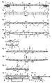
- the spring element according to the invention consists of FIGS. 1 and 2 at least one clamping element 4, which between the ends 5 and 6 in Longitudinal direction 7 runs and which is in at least a first transverse direction 32 is deflectable, is tensioned with tension and adjustable along and along the tensioning element 4 on the load side between the ends 5 and 6 interconnected chain elements 1 are arranged so that the Support chain elements 1 in the longitudinal direction 7 and around swivel axes 8, which is transverse to the longitudinal direction 7 and transverse to the first transverse direction 32 run, are pivotable relative to each other.
- the chain elements 1 are thereby articulated to each other that they with their from the tensioning element facing backs are firmly connected to an upper chord 14, which over the entire length of the spring element from one end 5 to extends other end 6 and is also firmly connected to the ends 5 and 6 and Resiliently deflectable in the transverse direction, but is pressure-resistant in the longitudinal direction 7.
- the chain elements 1 form in FIG Unloaded transverse direction with their front of the clamping element 4th averted back in its entirety a mirror-symmetrical crowned overall convex contour. Because of these different heights of the chain elements 1 is except for the ends 5 and 6, which are also the support points for the spring element form, one between the ends 5 and 6, at every point, the same sinking depth realizable.
- Fig. 5 shows in detail that the chain elements 1 only over the top chord 14th are interconnected, and on the end faces 9 only against each other be pressed, and these end faces when deflected in the first transverse direction roll on each other and the roll-off point has a transverse pivot axis represents.
- the chain elements 1 are on a lower flange 15 attached to a central 16 or lateral 17 support the Realize spring element while the clamping element 4 on the top runs.
- a spring element with an upper chord 14 is over a connecting element 18 connected to a female connector 19 to a approximately the same sinking depth of the ends 5 and 6 as between the ends 5 and 6 can be achieved.
- two female connectors are different Deflection and support in the longitudinal direction one behind the other connected. This combination can be advantageous in the seating area, especially in the Chair area can be used.
- FIG. 12 there are two spring elements, one with a long one Upper chord 14 and a short one with lower chord 15, via a connecting element 18, that runs in the deflection direction 32, arranged.
- This combination of two Spring elements allow an exact sinking depth of the upper chain element at all points in the longitudinal direction 7 and is particularly suitable for use in Nursing beds in connection with a central electromechanical control for different hardness requirements that exist from a medical point of view.
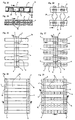
- exemplary embodiments are Spring element shown with central belt 21, which is advantageous in the seating area, especially used in the backrests of office chairs or car seats can, and with the tensioning elements 4 on both sides of this central belt run.
- FIG. 18 there is a spring element with an upper chord 14 shown, which replaces the chain elements 1 and by a continuous flexible hollow body 22 is formed, and instead of a clamping element 21, a Cross fabric 23, the tension task of the clamping element 4 takes over.
- damping and compensating elements 26 are located at an excessively strong and different load of the Spring elements such as B. in benches in public areas, the Clamping element 4 or the clamping device relieved.
- the upper chord of the spring element by means of individual elements 29, which are connected by continuous chain elements which form the Form pivot axes and fix the individual elements 29, formed and thereby offering the constructive possibility of larger contiguous areas for different relaxation areas with different requirements realize.
- the wide top chord 14 is for a controlled deflection has openings 30, chain elements 1 '' with four End faces 9 and a centering center 31 attached, the clamping elements 4 run lengthways and crossways and are in the center of the centering center cross and thereby a homogeneous deflection with a tapering Pressure distribution curve of the surface in both the longitudinal and transverse directions is realized.
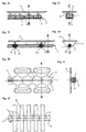
- Figures 36 and 37 show in longitudinal and cross section a variant in which the upper flange 14 protrudes at intervals against the tensioning element 4, has in particular integrally formed extensions 14 '.
- the chain elements 1 are plugged onto the free ends of the extensions 14 'and take them in appropriately shaped pockets that are slightly larger than that Extensions 14 '. Deformed transversely to the tensioning element when loaded on the top flange the upper chord 14, so that under certain circumstances also the extensions 14 'no longer are exactly parallel to each other, and the adjacent chain elements 1 roll something against each other with their mutually facing end faces 9 according to the effect of a joint.
- the clamping element 4 can be a Be tension belt, which lies on a lower groove of the chain elements 1.
- FIG. 38 shows a variant in which the chain elements 1 Pieces of pipe are in the direction of the clamping element 4, in this case one Clamping element with a round cross-section, such as a steel cable, which extends through the tube.
- the intermediate upper chord 14 and the tensioning element act primarily as tensioning element 1 4 located part of the cross section of the pipe sections, so that the hinge point the point of contact of these pipe sections on the end faces 9 opposite the extensions 14 '.
- FIG. 40 shows a variant similar to FIG. 36, but with the clamping element 4 again an element with a round cross-section, such as a steel cable, is used, whose primary difference is the shape of the top chord 14:
- the upper flange extends on both sides a multiple of the width of the extensions 14 'beyond these laterally is in Cut in the longitudinal direction from the sides at intervals apart from about Depth of the extensions 14 'and has large areas in these lateral projections Breakthroughs.
- Such a spring element provides support over a large area, without ventilation through the upper chord 14 within this area completely hindering it.
- FIG. 42 shows an embodiment similar to FIG. 26, with the difference that that on the side of the chain elements 1 facing away from the tensioning element 4 each chain element a laterally wide to the direction of the tensioning element 4 projecting cross-arm 28 is arranged to also by a single Spring element to offer a wide support surface.
- the chain elements 1 can be connected to each other via individual joints or via a Upper chord 14.
Landscapes
- Springs (AREA)
- Impact Printers (AREA)
- Finger-Pressure Massage (AREA)
- Devices For Conveying Motion By Means Of Endless Flexible Members (AREA)
Priority Applications (1)
| Application Number | Priority Date | Filing Date | Title |
|---|---|---|---|
| DK99114349T DK0974294T3 (da) | 1998-07-21 | 1999-07-21 | Strimmelformet fjederelement |
Applications Claiming Priority (2)
| Application Number | Priority Date | Filing Date | Title |
|---|---|---|---|
| DE19832689A DE19832689B4 (de) | 1998-07-21 | 1998-07-21 | Streifenförmiges Federelement |
| DE19832689 | 1998-07-21 |
Publications (3)
| Publication Number | Publication Date |
|---|---|
| EP0974294A2 true EP0974294A2 (fr) | 2000-01-26 |
| EP0974294A3 EP0974294A3 (fr) | 2001-06-20 |
| EP0974294B1 EP0974294B1 (fr) | 2004-11-24 |
Family
ID=7874755
Family Applications (1)
| Application Number | Title | Priority Date | Filing Date |
|---|---|---|---|
| EP99114349A Expired - Lifetime EP0974294B1 (fr) | 1998-07-21 | 1999-07-21 | Elément de ressort en forme de bande |
Country Status (5)
| Country | Link |
|---|---|
| EP (1) | EP0974294B1 (fr) |
| AT (1) | ATE282978T1 (fr) |
| DE (2) | DE19832689B4 (fr) |
| DK (1) | DK0974294T3 (fr) |
| ES (1) | ES2234186T3 (fr) |
Cited By (2)
| Publication number | Priority date | Publication date | Assignee | Title |
|---|---|---|---|---|
| WO2011103852A3 (fr) * | 2010-02-24 | 2011-10-20 | Dieter Mankau | Elément support |
| CN106163337A (zh) * | 2013-12-30 | 2016-11-23 | 爱克塞斯直接公司 | 单向刚性件和方法 |
Family Cites Families (3)
| Publication number | Priority date | Publication date | Assignee | Title |
|---|---|---|---|---|
| CH667001A5 (de) * | 1985-09-03 | 1988-09-15 | Hugo Degen | Untermatratze. |
| JPH0737613Y2 (ja) * | 1992-12-25 | 1995-08-30 | パラマウントベッド株式会社 | ベッドにおけるボトム構造 |
| DE9409812U1 (de) * | 1994-06-17 | 1995-10-19 | Hartmann, Siegbert, 32584 Löhne | Vorrichtung zur Härteeinstellung von in einem Bettlattenrost gelagerten Federleisten |
-
1998
- 1998-07-21 DE DE19832689A patent/DE19832689B4/de not_active Expired - Fee Related
-
1999
- 1999-07-21 DE DE59911125T patent/DE59911125D1/de not_active Expired - Lifetime
- 1999-07-21 ES ES99114349T patent/ES2234186T3/es not_active Expired - Lifetime
- 1999-07-21 DK DK99114349T patent/DK0974294T3/da active
- 1999-07-21 AT AT99114349T patent/ATE282978T1/de not_active IP Right Cessation
- 1999-07-21 EP EP99114349A patent/EP0974294B1/fr not_active Expired - Lifetime
Cited By (2)
| Publication number | Priority date | Publication date | Assignee | Title |
|---|---|---|---|---|
| WO2011103852A3 (fr) * | 2010-02-24 | 2011-10-20 | Dieter Mankau | Elément support |
| CN106163337A (zh) * | 2013-12-30 | 2016-11-23 | 爱克塞斯直接公司 | 单向刚性件和方法 |
Also Published As
| Publication number | Publication date |
|---|---|
| EP0974294B1 (fr) | 2004-11-24 |
| DK0974294T3 (da) | 2005-04-04 |
| DE19832689A1 (de) | 2000-01-27 |
| EP0974294A3 (fr) | 2001-06-20 |
| DE59911125D1 (de) | 2004-12-30 |
| ATE282978T1 (de) | 2004-12-15 |
| DE19832689B4 (de) | 2008-11-27 |
| ES2234186T3 (es) | 2005-06-16 |
Similar Documents
| Publication | Publication Date | Title |
|---|---|---|
| EP0996349B1 (fr) | Element d'appui pour la base de coussin de surfaces de siege ou de lit | |
| EP1056371B1 (fr) | Chassis de lit | |
| EP0270582B1 (fr) | Element pour etre assis ou couche | |
| EP2637526B1 (fr) | Élément ressort | |
| EP2622991B1 (fr) | Soutien de lordose, inclinaison de dossier, chaise et procédé de réglage d'un soutien de lordose | |
| DE1554084B2 (de) | Sitz, insbesondere Kraftfahrzeugsitz | |
| DE102012009646A1 (de) | Unterfederung für insbesondere eine Matratze | |
| EP0050293B1 (fr) | Dispositif pour renforcer de manière variable et en différents endroits les sommiers à lattes des meubles de couchage | |
| DE102015100703A1 (de) | Lattenrost | |
| CH540690A (de) | Vorrichtung zum Erleichtern oder Ermöglichen des Sitzens für behinderte Personen | |
| EP0974294B1 (fr) | Elément de ressort en forme de bande | |
| EP0539644B1 (fr) | Sommier à lattes | |
| EP0181591B1 (fr) | Support pour une personne couchée ou assise | |
| DE202017100229U1 (de) | Bettunterbau | |
| EP1902649A1 (fr) | Elément de support pour le soutien de lattes sur les longerons d'un sommier | |
| EP4277498B1 (fr) | Système d?appui | |
| DE202007008867U1 (de) | Anordnung mit einem Bettgestell und einer Kombinationsmatratze | |
| WO2024012812A1 (fr) | Élément de ressort de support pour matelas, agencement de ressort de support et système de ressort de support | |
| DE8809806U1 (de) | Federndes Bauelement zur Ausbildung einer Liegefläche eines Liegemöbels | |
| DE69717731T2 (de) | Sitz- oder Liege-element | |
| AT18076U1 (de) | Liegerahmen für Bett- und Sitzgestelle | |
| EP4516164A1 (fr) | Support de couchage et/ou d'assise en matériau élastique permanent | |
| DE19726793C1 (de) | Bettlattenrost mit Härtezoneneinstellung | |
| EP2409604A1 (fr) | Support à ressort des lattes d'un sommier à lattes | |
| DE2244592A1 (de) | Befederung fuer sitze oder liegen |
Legal Events
| Date | Code | Title | Description |
|---|---|---|---|
| PUAI | Public reference made under article 153(3) epc to a published international application that has entered the european phase |
Free format text: ORIGINAL CODE: 0009012 |
|
| AK | Designated contracting states |
Kind code of ref document: A2 Designated state(s): AT BE CH CY DE DK ES FI FR GB GR IE IT LI LU MC NL PT SE |
|
| AX | Request for extension of the european patent |
Free format text: AL;LT;LV;MK;RO;SI |
|
| PUAL | Search report despatched |
Free format text: ORIGINAL CODE: 0009013 |
|
| AK | Designated contracting states |
Kind code of ref document: A3 Designated state(s): AT BE CH CY DE DK ES FI FR GB GR IE IT LI LU MC NL PT SE |
|
| AX | Request for extension of the european patent |
Free format text: AL;LT;LV;MK;RO;SI |
|
| 17P | Request for examination filed |
Effective date: 20010619 |
|
| AKX | Designation fees paid |
Free format text: AT BE CH CY DE DK ES FI FR GB GR IE IT LI LU MC NL PT SE |
|
| 17Q | First examination report despatched |
Effective date: 20030224 |
|
| GRAP | Despatch of communication of intention to grant a patent |
Free format text: ORIGINAL CODE: EPIDOSNIGR1 |
|
| GRAS | Grant fee paid |
Free format text: ORIGINAL CODE: EPIDOSNIGR3 |
|
| GRAA | (expected) grant |
Free format text: ORIGINAL CODE: 0009210 |
|
| AK | Designated contracting states |
Kind code of ref document: B1 Designated state(s): AT BE CH CY DE DK ES FI FR GB GR IE IT LI LU MC NL PT SE |
|
| PG25 | Lapsed in a contracting state [announced via postgrant information from national office to epo] |
Ref country code: NL Free format text: LAPSE BECAUSE OF FAILURE TO SUBMIT A TRANSLATION OF THE DESCRIPTION OR TO PAY THE FEE WITHIN THE PRESCRIBED TIME-LIMIT Effective date: 20041124 Ref country code: IE Free format text: LAPSE BECAUSE OF FAILURE TO SUBMIT A TRANSLATION OF THE DESCRIPTION OR TO PAY THE FEE WITHIN THE PRESCRIBED TIME-LIMIT Effective date: 20041124 Ref country code: FI Free format text: LAPSE BECAUSE OF FAILURE TO SUBMIT A TRANSLATION OF THE DESCRIPTION OR TO PAY THE FEE WITHIN THE PRESCRIBED TIME-LIMIT Effective date: 20041124 |
|
| REG | Reference to a national code |
Ref country code: GB Ref legal event code: FG4D Free format text: NOT ENGLISH |
|
| REG | Reference to a national code |
Ref country code: CH Ref legal event code: EP |
|
| REF | Corresponds to: |
Ref document number: 59911125 Country of ref document: DE Date of ref document: 20041230 Kind code of ref document: P |
|
| REG | Reference to a national code |
Ref country code: IE Ref legal event code: FG4D Free format text: GERMAN |
|
| PG25 | Lapsed in a contracting state [announced via postgrant information from national office to epo] |
Ref country code: SE Free format text: LAPSE BECAUSE OF FAILURE TO SUBMIT A TRANSLATION OF THE DESCRIPTION OR TO PAY THE FEE WITHIN THE PRESCRIBED TIME-LIMIT Effective date: 20050224 Ref country code: GR Free format text: LAPSE BECAUSE OF FAILURE TO SUBMIT A TRANSLATION OF THE DESCRIPTION OR TO PAY THE FEE WITHIN THE PRESCRIBED TIME-LIMIT Effective date: 20050224 |
|
| REG | Reference to a national code |
Ref country code: CH Ref legal event code: NV Representative=s name: SCHMAUDER & PARTNER AG PATENTANWALTSBUERO |
|
| REG | Reference to a national code |
Ref country code: DK Ref legal event code: T3 |
|
| GBT | Gb: translation of ep patent filed (gb section 77(6)(a)/1977) |
Effective date: 20050324 |
|
| NLV1 | Nl: lapsed or annulled due to failure to fulfill the requirements of art. 29p and 29m of the patents act | ||
| REG | Reference to a national code |
Ref country code: ES Ref legal event code: FG2A Ref document number: 2234186 Country of ref document: ES Kind code of ref document: T3 |
|
| REG | Reference to a national code |
Ref country code: IE Ref legal event code: FD4D |
|
| PG25 | Lapsed in a contracting state [announced via postgrant information from national office to epo] |
Ref country code: IT Free format text: LAPSE BECAUSE OF NON-PAYMENT OF DUE FEES Effective date: 20050721 Ref country code: CY Free format text: LAPSE BECAUSE OF FAILURE TO SUBMIT A TRANSLATION OF THE DESCRIPTION OR TO PAY THE FEE WITHIN THE PRESCRIBED TIME-LIMIT Effective date: 20050721 Ref country code: AT Free format text: LAPSE BECAUSE OF NON-PAYMENT OF DUE FEES Effective date: 20050721 |
|
| PG25 | Lapsed in a contracting state [announced via postgrant information from national office to epo] |
Ref country code: MC Free format text: LAPSE BECAUSE OF NON-PAYMENT OF DUE FEES Effective date: 20050731 Ref country code: BE Free format text: LAPSE BECAUSE OF NON-PAYMENT OF DUE FEES Effective date: 20050731 |
|
| PLBE | No opposition filed within time limit |
Free format text: ORIGINAL CODE: 0009261 |
|
| STAA | Information on the status of an ep patent application or granted ep patent |
Free format text: STATUS: NO OPPOSITION FILED WITHIN TIME LIMIT |
|
| 26N | No opposition filed |
Effective date: 20050825 |
|
| ET | Fr: translation filed | ||
| PGFP | Annual fee paid to national office [announced via postgrant information from national office to epo] |
Ref country code: GB Payment date: 20060719 Year of fee payment: 8 Ref country code: CH Payment date: 20060719 Year of fee payment: 8 |
|
| BERE | Be: lapsed |
Owner name: *MANKAU DIETER Effective date: 20050731 |
|
| PG25 | Lapsed in a contracting state [announced via postgrant information from national office to epo] |
Ref country code: PT Free format text: LAPSE BECAUSE OF NON-PAYMENT OF DUE FEES Effective date: 20050424 |
|
| REG | Reference to a national code |
Ref country code: CH Ref legal event code: PL |
|
| REG | Reference to a national code |
Ref country code: DK Ref legal event code: EBP |
|
| GBPC | Gb: european patent ceased through non-payment of renewal fee |
Effective date: 20070721 |
|
| PG25 | Lapsed in a contracting state [announced via postgrant information from national office to epo] |
Ref country code: LI Free format text: LAPSE BECAUSE OF NON-PAYMENT OF DUE FEES Effective date: 20070731 Ref country code: CH Free format text: LAPSE BECAUSE OF NON-PAYMENT OF DUE FEES Effective date: 20070731 |
|
| PGFP | Annual fee paid to national office [announced via postgrant information from national office to epo] |
Ref country code: FR Payment date: 20070723 Year of fee payment: 9 Ref country code: DK Payment date: 20060721 Year of fee payment: 8 |
|
| PG25 | Lapsed in a contracting state [announced via postgrant information from national office to epo] |
Ref country code: GB Free format text: LAPSE BECAUSE OF NON-PAYMENT OF DUE FEES Effective date: 20070721 |
|
| REG | Reference to a national code |
Ref country code: FR Ref legal event code: ST Effective date: 20080331 |
|
| PG25 | Lapsed in a contracting state [announced via postgrant information from national office to epo] |
Ref country code: DK Free format text: LAPSE BECAUSE OF NON-PAYMENT OF DUE FEES Effective date: 20070731 |
|
| PG25 | Lapsed in a contracting state [announced via postgrant information from national office to epo] |
Ref country code: FR Free format text: LAPSE BECAUSE OF NON-PAYMENT OF DUE FEES Effective date: 20070731 |
|
| PGFP | Annual fee paid to national office [announced via postgrant information from national office to epo] |
Ref country code: ES Payment date: 20090714 Year of fee payment: 11 |
|
| REG | Reference to a national code |
Ref country code: ES Ref legal event code: FD2A Effective date: 20110818 |
|
| REG | Reference to a national code |
Ref country code: DE Ref legal event code: R082 Ref document number: 59911125 Country of ref document: DE Representative=s name: PATENTANWAELTE OLBRICHT, BUCHHOLD, KEULERTZ PA, DE Ref country code: DE Ref legal event code: R082 Ref document number: 59911125 Country of ref document: DE Representative=s name: HEINRICH ERB PARTNER RECHTSANWAELTE PATENTANWA, DE Ref country code: DE Ref legal event code: R082 Ref document number: 59911125 Country of ref document: DE Representative=s name: HEINRICH ERB PARTNER, DE |
|
| REG | Reference to a national code |
Ref country code: DE Ref legal event code: R083 Ref document number: 59911125 Country of ref document: DE |
|
| PG25 | Lapsed in a contracting state [announced via postgrant information from national office to epo] |
Ref country code: ES Free format text: LAPSE BECAUSE OF NON-PAYMENT OF DUE FEES Effective date: 20100722 |
|
| PGFP | Annual fee paid to national office [announced via postgrant information from national office to epo] |
Ref country code: DE Payment date: 20140714 Year of fee payment: 16 |
|
| REG | Reference to a national code |
Ref country code: DE Ref legal event code: R082 Ref document number: 59911125 Country of ref document: DE Representative=s name: PATENTANWAELTE OLBRICHT, BUCHHOLD, KEULERTZ PA, DE |
|
| REG | Reference to a national code |
Ref country code: DE Ref legal event code: R119 Ref document number: 59911125 Country of ref document: DE |
|
| PG25 | Lapsed in a contracting state [announced via postgrant information from national office to epo] |
Ref country code: DE Free format text: LAPSE BECAUSE OF NON-PAYMENT OF DUE FEES Effective date: 20160202 |