EP0974302A2 - Dispositif de rincage pour lave-vaisselle - Google Patents
Dispositif de rincage pour lave-vaisselle Download PDFInfo
- Publication number
- EP0974302A2 EP0974302A2 EP99113672A EP99113672A EP0974302A2 EP 0974302 A2 EP0974302 A2 EP 0974302A2 EP 99113672 A EP99113672 A EP 99113672A EP 99113672 A EP99113672 A EP 99113672A EP 0974302 A2 EP0974302 A2 EP 0974302A2
- Authority
- EP
- European Patent Office
- Prior art keywords
- washing
- chamber
- arm
- rinsing
- axis
- Prior art date
- Legal status (The legal status is an assumption and is not a legal conclusion. Google has not performed a legal analysis and makes no representation as to the accuracy of the status listed.)
- Granted
Links
- 239000007921 spray Substances 0.000 title claims abstract description 22
- 239000007788 liquid Substances 0.000 claims abstract description 44
- 238000005406 washing Methods 0.000 claims abstract description 31
- 238000011010 flushing procedure Methods 0.000 description 10
- XLYOFNOQVPJJNP-UHFFFAOYSA-N water Substances O XLYOFNOQVPJJNP-UHFFFAOYSA-N 0.000 description 8
- 239000002184 metal Substances 0.000 description 4
- 238000004140 cleaning Methods 0.000 description 3
- 238000010586 diagram Methods 0.000 description 1
- 238000004851 dishwashing Methods 0.000 description 1
- 230000000694 effects Effects 0.000 description 1
- 239000012530 fluid Substances 0.000 description 1
- 230000003993 interaction Effects 0.000 description 1
- 230000002262 irrigation Effects 0.000 description 1
- 238000003973 irrigation Methods 0.000 description 1
- 238000009420 retrofitting Methods 0.000 description 1
Images

Classifications
-
- A—HUMAN NECESSITIES
- A47—FURNITURE; DOMESTIC ARTICLES OR APPLIANCES; COFFEE MILLS; SPICE MILLS; SUCTION CLEANERS IN GENERAL
- A47L—DOMESTIC WASHING OR CLEANING; SUCTION CLEANERS IN GENERAL
- A47L15/00—Washing or rinsing machines for crockery or tableware
- A47L15/14—Washing or rinsing machines for crockery or tableware with stationary crockery baskets and spraying devices within the cleaning chamber
- A47L15/18—Washing or rinsing machines for crockery or tableware with stationary crockery baskets and spraying devices within the cleaning chamber with movably-mounted spraying devices
- A47L15/22—Rotary spraying devices
- A47L15/23—Rotary spraying devices moved by means of the sprays
Definitions
- the invention relates to a washing or rinsing device for a dishwasher according to the preamble of Claim 1.
- Dishwashers have especially for the A rectangular wash container, the front of which is provided with a loading door in order to Access to the in the dishwasher on rails to arrange arranged baskets.
- Within the Dishwasher is arranged at least one arm, which is rotatable about an axis.
- the wash arm can rotate in the dishwasher, it must be designed so that it moves in on a horizontal plane sweeps a circular area that itself within the rectangular or horizontal section square housing of the dishwasher.
- European patent application 0 559 466 A1 relates to this Problem of insufficient loading on the corner areas a dishwasher with rinsing liquid. This Problem is solved by four special rinse arms that like this are arranged that special corner areas of the Dishwasher will be subjected to more. These four Auxiliary wash arms each have only one inner one Hollow chamber and increase the total water consumption as a The majority of those emerging from these auxiliary rinse arms Liquid directly against the inner walls of the Dishwasher is directed.
- the German utility model 297 18 777 U1 also applies the problem of insufficient loading on the corners a dishwasher with rinsing liquid.
- the total water consumption very much high because the auxiliary rinse arm, depending on the geometry of the Dishwasher, brushes closely against the inner wall and therefore a large amount of flushing liquid in one Area in which they are not used can.
- the invention has for its object a washing or Propose a washing device for a dishwasher, in which the loading of the corner areas is improved and yet the total water consumption was kept low can be.
- the invention is based on the idea that the rotatable washing or rinsing arm carried on one axis two separate Has chambers, each chamber at least one Inlet opening and at least one outlet opening for Has washing or rinsing liquid.
- the at least one outlet opening as a corner spray nozzle is trained and only in defined rotational positions of the Washing or rinsing arm with washing or rinsing liquid can be acted upon, the corner area of the Dishwasher with an extra jet of washing or flush liquid without the Water consumption increased significantly. If too The common usage in the following is always based on The terms “wash arm” and "wash liquid” are used, should be clear that both rinse arms and Wash arms are referred to, from which rinsing or Washing liquid escapes.
- corner spray nozzle is understood to mean a nozzle whose geometry is designed so that in the corner area a crockery basket arranged with Flush liquid can be applied.
- the axis points a single flow space for rinsing liquid. This has the advantage that the axis is simple and inexpensive can be executed; above all, however, can be a simple way an existing flushing device for a Dishwasher using the herein Convert described rinse arm.
- the rinse arm includes a hub that is on the axle can be attached and carries and still has the flush arm the axis has four holes with the flow space in Connect.
- the hub also has four holes, those defined with the second chamber of the rinse arm and in Rotation positions with the four holes in the axis in Flow connection.
- This possibility of targeted Actuation of the corner spray nozzles is characterized by a very simple design of the axis. Also this allows retrofitting of existing ones Realize dishwashers. Beyond that by arranging the four holes in the axis the pressure build-up of the flushing liquid in the second chamber of the Low rinsing and the flow through the corner spray nozzles defined angular ranges of the circulation of the wash arm realize.
- this measure which is characterized, for example, by training an annular groove on the outer circumference of the axis, or one Technically implement the annular groove on the inner circumference of the hub ensured that the outlet openings of the rinse arm, the communicate with the first chamber during the Rotary movement of the wash arm evenly with wash liquid are applied, while the corner spray nozzles only in those areas during the circulation of the wash arm are flowed through, in which a targeted application of the Corner areas is needed.
- the farthest outlet openings of the first chamber removed from the hub of the rinse arm designed so that they in the rinsing liquid give an angle radially inwards. This measure represents sure that the rinsing liquid dispensed is not against the Walls of the dishwasher is directed and thus remains unused.
- the special Corner spray nozzles can be used using the Rinsing liquid on the dishwashing function of the dishwasher optimize it.
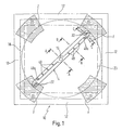
- Fig. 1 is a horizontal section through a schematic Dishwasher shown, generally with Reference number 10 is called.
- the dishwasher usually has one around a horizontal axis pivoting door, but not in the present case is shown. When closed, the interior the dishwasher is delimited by four side walls 12, which have the same dimensions in the present case, so that the interior of the dishwasher 10 in horizontal Cut has a square cross section.
- Dish rack 23 which is indicated by broken lines and usually along rails that follow the Side walls are located, is held displaceably.
- the Dish rack 23 has the cross section of the interior of the Dishwasher adapted one essentially square shape in the viewing direction according to FIG. 1.
- a rinsing device which consists of a Flush arm 14 and an axis 16, on which the Rinse arm is rotatably held.
- the rinse arm 14 is regarding its length designed so that during its Rotating movement in the interior of the dishwasher to the Can sweep along side walls 12 without this touch.
- Fig. 1 shows the corresponding circumferential circle 18.
- the rinse arm 14 has corner spray nozzles 22 which are special are designed to act upon the To achieve flush areas not reached corner areas 20. For this are near the radially outer end of the flush arm Nozzles 22 arranged depending on the geometry of the Dishwasher rinsing liquid essentially after given up or down. In addition, they are Corner spray nozzles 22 shaped so that when the Flushing liquid up or down also one Directional component is generated radially outwards.
- the corner spray nozzles are not during the entire circulation of the Flush arm 14 in operation, but only when the Arm is located in an area where it is in one of the Diagonals to the rectangular cross section of the Dishwasher is aligned. Because of the targeted Operation of the corner spray nozzles 22 in this area forms one schematically in Fig. 1 in each of the corner areas shown area F, which the delivery of the from Corner spray nozzles 22 leaking rinsing liquid in the case represents in which the escaping liquid is not by the Presence of the side walls 12 would be limited.
- the diagram in Fig. 1 is also schematic shown example each a part of the ejected Liquid collected from the side walls 12.
- Fig. 2 shows a sectional view along the line A-A in Fig. 1 shows and gives a possible configuration of the rinse arm 14 and the flow connection to the axis 16 to the targeted application of the corner spray nozzle only in the Technically implement corner area.
- the flush arm 14 consists of shaped elements, each on the Hub 24 are attached.
- the lower element 28 engages a first paragraph 30 in the hub 24 while the upper element 26 is fitted in a paragraph 32.
- the upper element is crimped around lower element 28, around the upper member 26 and the lower member 28 with each other connect to.
- Through the two elements 26 and 28 in Interaction with the hub 24 creates a cavity that is divided into two chambers by a cutting disc 34.
- the cutting disc only over part of the radial extent of the flush arm and the elements 26 and 28 so be shaped to delimit two separate chambers.
- the hub 24 has an inner diameter which is dimensioned in this way is that it is pushed onto the axis 16 with little play can be.
- the axial fixation between axis 16 and hub 24 to each other is not shown in Fig. 2, because here any solution known to the person skilled in the art can be used can. Axial fixation must be within narrow tolerances be ensured, as will be described later the flow channels for the passage of the rinsing liquid from the interior of the axis 16 designed as a hollow cylinder ensured in the first or second chamber of the wash arm can be.
- first bores 40 which connect between a annular groove 42 on the outer circumference of the axis 16 with the Create the first chamber 36.
- the annular groove 42 is through Bores 44 with the inner flow space 46 of the axis 16 connected so that during the operation of the feed pump for Always flush the annular groove with liquid is filled under pressure, which during the rotation of the Flush arm 14 can penetrate into the first chamber 36.
- Outlet nozzles through which are not shown in FIG the rinsing liquid from the first chamber 36 towards the baskets are pushed out. How to get out of the 1, these outlet nozzles 48 radially spaced from each other on the wash arm 14 be and to the needs of each Dishwasher regarding their position as well as theirs Design, the influence on the geometry and the strength of the ejected liquid. It there is also the possibility that on the rinse arm 14th arranged outlet nozzles 48 to arrange or their Adjust the ejection direction so that when operating the Liquid pump (not shown) by the Recoil effect of those emerging from the outlet nozzles Liquid the rinse arm 14 about the axis 16 in rotation is transferred.
- second bores 50 are in the hub 24 shown in FIG Sectional view with corresponding holes 52 in the Align axis 16.
- the Flow connection between the inner flow space 46 of the Axis 16 and the second chamber 38 designed so that the Only then do the rinsing liquid flow into the second chamber 38 can when the flush arm 14 is in a diagonal position is as shown in Fig. 1.
- four holes 52 are in the stationary in the Dishwasher arranged axis 16 provided that the four second bores 50 only at a rotational position of the Flush arm corresponding to the position shown in Fig. 1 as well are rotated by 90 °.
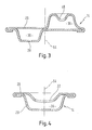
- FIG. 3 and 4 each show those shown in Fig. 1 Cuts along lines B-B and C-C. As from the figures can be seen is in the area of the cuts B-B and C-C no more cutting disc between the top, made of sheet metal or Plastic-made element 26 and the corresponding lower element made of sheet metal or plastic 28 intended. While in the range shown in Fig. 3 Sectional view B-B, the first chamber 36 and the second Chamber 38 offset from the longitudinal axis 54 of the flush arm 14 are arranged and the upper element 26 and lower element 28 lie close together in the area of the axis 54 in order to Flow connection between the first chamber 36 and the Preventing second chamber 38 is in the area of Sectional view C-C only the second chamber 38 formed which the flow connection to the corner spray nozzle 22 manufactures.
- the corner spray nozzles 22 are shaped so that the jet on Flushing liquid not only in the vertical direction, but also is also delivered at an angle radially outwards to reach the corner areas 20 (see FIG. 1).
- the outlet nozzles 48 which are independent of the Rotational position of the rinse arm to be operated Requirements for good cleaning in the Dishwasher, but also a small one Be adapted to water consumption. It could be useful here be the radially outermost outlet nozzles 48a so that the rinsing liquid is not only in vertical direction, but also at an angle radially is delivered inside. This makes it unnecessary Avoid water loss caused by hitting the Flushing liquid on the side walls 12 and the unused Running down the side walls is generated.
Landscapes
- Washing And Drying Of Tableware (AREA)
- Cleaning By Liquid Or Steam (AREA)
Applications Claiming Priority (2)
| Application Number | Priority Date | Filing Date | Title |
|---|---|---|---|
| DE19832982 | 1998-07-22 | ||
| DE19832982A DE19832982C2 (de) | 1998-07-22 | 1998-07-22 | Spülvorrichtung für eine Geschirrspülmaschine |
Publications (3)
| Publication Number | Publication Date |
|---|---|
| EP0974302A2 true EP0974302A2 (fr) | 2000-01-26 |
| EP0974302A3 EP0974302A3 (fr) | 2000-03-29 |
| EP0974302B1 EP0974302B1 (fr) | 2003-10-29 |
Family
ID=7874926
Family Applications (1)
| Application Number | Title | Priority Date | Filing Date |
|---|---|---|---|
| EP99113672A Expired - Lifetime EP0974302B1 (fr) | 1998-07-22 | 1999-07-15 | Dispositif de rincage pour lave-vaisselle |
Country Status (4)
| Country | Link |
|---|---|
| US (1) | US6325083B1 (fr) |
| EP (1) | EP0974302B1 (fr) |
| AT (1) | ATE252865T1 (fr) |
| DE (2) | DE19832982C2 (fr) |
Cited By (5)
| Publication number | Priority date | Publication date | Assignee | Title |
|---|---|---|---|---|
| EP1238622A3 (fr) * | 2001-03-10 | 2003-03-19 | AEG Hausgeräte GmbH | Lave-vaiselle avec dispositif d'arrosage monté tournant et procédé de commande pour celui-ci |
| DE102004018878A1 (de) * | 2004-04-15 | 2005-11-10 | Miele & Cie. Kg | Geschirrspülmaschine mit einem Spülbehälter in dem wenigstens ein Sprüharm angeordnet ist |
| DE102005026558B3 (de) * | 2005-06-08 | 2006-11-16 | Miele & Cie. Kg | Geschirrspülmaschine mit einem Spülbehälter in dem wenigstens ein Sprüharm angeordnet ist |
| EP1731081B2 (fr) † | 2005-06-08 | 2013-07-10 | Miele & Cie. KG | Lave-vaisselle |
| ITTO20130614A1 (it) * | 2013-07-19 | 2015-01-20 | Premark Feg Llc | Dispositivo di lavaggio e risciacquo combinato e macchina lavastoviglie includente tale dispositivo |
Families Citing this family (28)
| Publication number | Priority date | Publication date | Assignee | Title |
|---|---|---|---|---|
| DE10120894B4 (de) * | 2001-04-27 | 2007-03-01 | Miele & Cie. Kg | Verfahren zum Spülen von Spülgut |
| DE10134917B4 (de) * | 2001-07-18 | 2006-03-16 | AEG Hausgeräte GmbH | Geschirrspülmaschine mit veränderbarer Flüssigkeitsverteilung |
| DE102006012080A1 (de) * | 2006-03-14 | 2007-09-27 | Miele & Cie. Kg | Spülmaschine |
| DE102006007327A1 (de) * | 2006-02-16 | 2007-08-30 | BSH Bosch und Siemens Hausgeräte GmbH | Geschirrspülmaschine mit Sprühvorrichtung |
| KR100706666B1 (ko) * | 2006-05-25 | 2007-04-13 | 세메스 주식회사 | 기판을 처리하는 장치 및 방법, 그리고 이에 사용되는분사헤드 |
| US7896977B2 (en) * | 2007-12-19 | 2011-03-01 | Whirlpool Corporation | Dishwasher with sequencing corner nozzles |
| US8166983B2 (en) * | 2007-12-21 | 2012-05-01 | Wolf Appliance, Inc. | Fluid supply system for appliance |
| US7988791B2 (en) * | 2008-01-14 | 2011-08-02 | Whirlpool Corporation | Dishwasher with multiple wash zones |
| DE102009007297A1 (de) | 2009-02-03 | 2010-08-12 | Miele & Cie. Kg | Spülautomat mit einem quaderförmigen Spülraum |
| EP2512695A1 (fr) | 2009-12-17 | 2012-10-24 | Jackson MSC LLC | Bras de système de lavage de produits |
| US8852351B2 (en) * | 2010-10-20 | 2014-10-07 | Whirlpool Corporation | Dishwasher with wash load detection |
| US8801863B2 (en) * | 2011-05-11 | 2014-08-12 | Whirlpool Corporation | Dishwasher with rack corner spray system |
| US9414736B2 (en) | 2011-09-22 | 2016-08-16 | Whirlpool Corporation | Dishwasher with directional spray |
| US9492055B2 (en) | 2011-09-22 | 2016-11-15 | Whirlpool Corporation | Dishwasher with spray system |
| US9693672B2 (en) | 2011-09-22 | 2017-07-04 | Whirlpool Corporation | Dishwasher with sprayer |
| US9375128B2 (en) | 2011-09-22 | 2016-06-28 | Whirlpool Corporation | Dishwasher with spray system |
| US9763554B2 (en) * | 2012-02-14 | 2017-09-19 | Premark Feg L.L.G. | Warewash machine with removable rotating arm and related method |
| USD675386S1 (en) * | 2012-02-16 | 2013-01-29 | Electrolux Home Products, Inc. | Dishwasher spray arm |
| USD675387S1 (en) * | 2012-02-16 | 2013-01-29 | Electrolux Home Products, Inc. | Dishwasher spray arm with satellite spray arm |
| TWI468144B (zh) * | 2012-05-11 | 2015-01-11 | Univ Nat Central | 用於重建手術之量測與導引裝置 |
| US9295368B2 (en) | 2013-03-01 | 2016-03-29 | Whirlpool Corporation | Dishwasher with hydraulically driven sprayer |
| US9532701B2 (en) | 2013-03-01 | 2017-01-03 | Whirlpool Corporation | Dishwasher with sprayer |
| KR101998571B1 (ko) | 2013-05-21 | 2019-07-10 | 삼성전자주식회사 | 노즐 어셈블리 및 이를 구비하는 식기세척기 |
| US9713413B2 (en) | 2013-07-01 | 2017-07-25 | Whirlpool Corporation | Dishwasher for treating dishes |
| US9532699B2 (en) | 2013-07-15 | 2017-01-03 | Whirlpool Corporation | Dishwasher with sprayer |
| DE202014105113U1 (de) | 2014-10-27 | 2014-11-03 | Illinois Tool Works Inc. | Spülarmsystem für Spülmaschine |
| US10149593B2 (en) * | 2016-10-07 | 2018-12-11 | Haier Us Appliance Solutions, Inc. | Spray arm assembly for dishwasher appliance |
| US11147430B2 (en) | 2019-03-27 | 2021-10-19 | Midea Group Co., Ltd. | Dishwasher including rack corner sprayers |
Family Cites Families (27)
| Publication number | Priority date | Publication date | Assignee | Title |
|---|---|---|---|---|
| US1675192A (en) * | 1926-07-26 | 1928-06-26 | Charles A Murdoch | Washing machine |
| NL56548C (fr) * | 1941-09-22 | |||
| US2748944A (en) * | 1954-05-03 | 1956-06-05 | Infilco Inc | Corner sweeping means for clarification basins |
| US3058479A (en) * | 1957-07-19 | 1962-10-16 | Waste King Corp | Dishwasher |
| US3468486A (en) * | 1967-02-02 | 1969-09-23 | Gen Motors Corp | Dishwasher with multiple spray arm |
| DE1628518A1 (de) * | 1967-09-09 | 1971-04-29 | Bosch Hausgeraete Gmbh | Geschirrspuelmaschine |
| GB1286820A (en) * | 1968-12-12 | 1972-08-23 | Hoover Ltd | Improvements relating to dish washing machines |
| CH519902A (fr) * | 1970-01-29 | 1972-03-15 | Frame Sa | Rotor d'aspersion d'une machine à laver la vaissele et la verrerie industrielle |
| DE7024995U (de) * | 1970-07-03 | 1971-03-11 | Robert Bosch Gmbh | Geschirrspülmaschine |
| JPS4944751B1 (fr) * | 1970-08-28 | 1974-11-29 | ||
| US3771725A (en) * | 1972-05-12 | 1973-11-13 | Gen Electric | Washing appliance having an improved spray arm assembly |
| US3941139A (en) * | 1974-08-15 | 1976-03-02 | Whirlpool Corporation | Dishwasher spray assembly with intermittently operating nozzles |
| US4509687A (en) | 1983-07-20 | 1985-04-09 | General Electric Company | Multiple spray distribution system for a domestic dishwasher |
| US4827563A (en) * | 1986-09-16 | 1989-05-09 | Gordon Len C | Tank cleaning apparatus and method |
| DE3813510A1 (de) * | 1988-04-22 | 1989-11-02 | Licentia Gmbh | Geschirrspuelmaschine mit drehbar gelagerter spruehvorrichtung |
| JPH0299026A (ja) * | 1988-10-07 | 1990-04-11 | Matsushita Electric Ind Co Ltd | 食器洗浄機 |
| JP2743665B2 (ja) * | 1991-11-14 | 1998-04-22 | 松下電器産業株式会社 | 食器洗浄機 |
| US5267582A (en) * | 1992-01-21 | 1993-12-07 | Maytag Corporation | Wash arm construction |
| DE69304740T2 (de) * | 1992-03-06 | 1997-04-03 | Nippon Senjoki Co Ltd | Geschirrspülmaschine |
| JP3415666B2 (ja) * | 1992-12-17 | 2003-06-09 | ホシザキ電機株式会社 | 食器洗浄機における洗浄ノズル |
| US5477874A (en) * | 1993-08-13 | 1995-12-26 | Matsushita Electric Industrial Co., Ltd. | Dishwasher |
| JPH06315450A (ja) * | 1993-05-07 | 1994-11-15 | Hitachi Ltd | 食器洗い乾燥機 |
| IT235027Y1 (it) * | 1994-06-16 | 2000-03-31 | Zanussi Elettrodomestici | Lavastoviglie con mulinello rotante di spruzzatura |
| US5464482A (en) * | 1994-11-07 | 1995-11-07 | Maytag Corporation | Washarm assembly for dishwasher |
| KR0122507Y1 (ko) * | 1996-06-14 | 1998-08-17 | 배순훈 | 식기세척기의 세척수분사장치 |
| US5944037A (en) * | 1996-10-16 | 1999-08-31 | Samsung Electronics Co., Ltd. | Water spray apparatus for tableware washing machine |
| IT1289398B1 (it) * | 1996-11-06 | 1998-10-02 | Electrolux Zanussi Elettrodome | Lavastoviglie con mezzi di spruzzatura perfezionati |
-
1998
- 1998-07-22 DE DE19832982A patent/DE19832982C2/de not_active Expired - Fee Related
-
1999
- 1999-07-15 EP EP99113672A patent/EP0974302B1/fr not_active Expired - Lifetime
- 1999-07-15 DE DE59907510T patent/DE59907510D1/de not_active Expired - Fee Related
- 1999-07-15 US US09/354,212 patent/US6325083B1/en not_active Expired - Fee Related
- 1999-07-15 AT AT99113672T patent/ATE252865T1/de not_active IP Right Cessation
Cited By (7)
| Publication number | Priority date | Publication date | Assignee | Title |
|---|---|---|---|---|
| EP1238622A3 (fr) * | 2001-03-10 | 2003-03-19 | AEG Hausgeräte GmbH | Lave-vaiselle avec dispositif d'arrosage monté tournant et procédé de commande pour celui-ci |
| DE102004018878A1 (de) * | 2004-04-15 | 2005-11-10 | Miele & Cie. Kg | Geschirrspülmaschine mit einem Spülbehälter in dem wenigstens ein Sprüharm angeordnet ist |
| DE102004018878B4 (de) * | 2004-04-15 | 2006-01-05 | Miele & Cie. Kg | Geschirrspülmaschine mit einem Spülbehälter in dem wenigstens ein Sprüharm angeordnet ist |
| DE102005026558B3 (de) * | 2005-06-08 | 2006-11-16 | Miele & Cie. Kg | Geschirrspülmaschine mit einem Spülbehälter in dem wenigstens ein Sprüharm angeordnet ist |
| EP1731081B2 (fr) † | 2005-06-08 | 2013-07-10 | Miele & Cie. KG | Lave-vaisselle |
| ITTO20130614A1 (it) * | 2013-07-19 | 2015-01-20 | Premark Feg Llc | Dispositivo di lavaggio e risciacquo combinato e macchina lavastoviglie includente tale dispositivo |
| WO2015009916A1 (fr) * | 2013-07-19 | 2015-01-22 | Premark Feg L.L.C. | Dispositif combiné de lavage et de rinçage et lave-vaisselle pourvu de celui-ci |
Also Published As
| Publication number | Publication date |
|---|---|
| DE59907510D1 (de) | 2003-12-04 |
| DE19832982C2 (de) | 2000-08-03 |
| EP0974302B1 (fr) | 2003-10-29 |
| US6325083B1 (en) | 2001-12-04 |
| DE19832982A1 (de) | 2000-02-10 |
| ATE252865T1 (de) | 2003-11-15 |
| EP0974302A3 (fr) | 2000-03-29 |
Similar Documents
| Publication | Publication Date | Title |
|---|---|---|
| EP0974302B1 (fr) | Dispositif de rincage pour lave-vaisselle | |
| EP2404539B1 (fr) | Répartiteur d'eau pour un appareil ménager véhiculant de l'eau | |
| EP1731081B1 (fr) | Lave-vaisselle | |
| EP2214546B1 (fr) | Appareil électroménager à circulation d'eau et comportant un dispositif répartiteur d'eau | |
| DE3426004C2 (de) | Geschirrspülmaschine | |
| EP2217125A1 (fr) | Appareil menager a circulation d'eau equipe d'un raccordement d'eau | |
| EP0301367B1 (fr) | Appareil d'arrosage | |
| DE60013345T2 (de) | Geschirrspülmaschine mit pulsierenden Wasserstrahlen | |
| DE202004013786U1 (de) | Geschirrspülmaschine mit Flüssigkeitsverteilungseinrichtung | |
| EP2556781B1 (fr) | Agencement de bras pulvérisateur d'un lave-vaisselle | |
| DE102005026558B3 (de) | Geschirrspülmaschine mit einem Spülbehälter in dem wenigstens ein Sprüharm angeordnet ist | |
| DE3820080A1 (de) | Handbrause mit einem rotierenden buerstensatz | |
| DE102004018878B4 (de) | Geschirrspülmaschine mit einem Spülbehälter in dem wenigstens ein Sprüharm angeordnet ist | |
| EP1634526B1 (fr) | Lave vaisselle avec dispositif d'arrosage | |
| DE102010043021B4 (de) | Geschirrspülmaschine, insbesondere Haushaltsgeschirrspülmaschine | |
| EP4003126B1 (fr) | Lave-vaisselle domestique | |
| DE102007029701B4 (de) | Waschsystem für eine Geschirrspülmaschine sowie Geschirrspülmaschine | |
| EP1005821B1 (fr) | Dispositif-infuseur (mono-infuseur) pour la préparation du café ou du thé | |
| DE102017105589B4 (de) | Sprüheinrichtung für eine Geschirrspülmaschine | |
| DE1191527B (de) | Geschirrspuelmaschine | |
| DE69202829T2 (de) | Geschirrspülmaschine mit horizontaldrehendem Sprüharm mit zwei stabilen Positionen in vertikaler Richtung. | |
| DE202005021574U1 (de) | Behälterreinigungsvorrichtung | |
| DE3813510A1 (de) | Geschirrspuelmaschine mit drehbar gelagerter spruehvorrichtung | |
| DE102025104758B3 (de) | Lager-Sprüharm-Anordnung, Haushalts-Geschirrspülmaschine und Verfahren | |
| DE102018209532B4 (de) | Wasserweiche für eine Haushalts-Geschirrspülmaschine |
Legal Events
| Date | Code | Title | Description |
|---|---|---|---|
| PUAI | Public reference made under article 153(3) epc to a published international application that has entered the european phase |
Free format text: ORIGINAL CODE: 0009012 |
|
| AK | Designated contracting states |
Kind code of ref document: A2 Designated state(s): AT BE CH CY DE DK ES FI FR GB GR IE IT LI LU MC NL PT SE |
|
| AX | Request for extension of the european patent |
Free format text: AL;LT;LV;MK;RO;SI |
|
| PUAL | Search report despatched |
Free format text: ORIGINAL CODE: 0009013 |
|
| AK | Designated contracting states |
Kind code of ref document: A3 Designated state(s): AT BE CH CY DE DK ES FI FR GB GR IE IT LI LU MC NL PT SE |
|
| AX | Request for extension of the european patent |
Free format text: AL;LT;LV;MK;RO;SI |
|
| 17P | Request for examination filed |
Effective date: 20000717 |
|
| AKX | Designation fees paid |
Free format text: AT BE CH CY DE DK ES FI FR GB GR IE IT LI LU MC NL PT SE |
|
| GRAH | Despatch of communication of intention to grant a patent |
Free format text: ORIGINAL CODE: EPIDOS IGRA |
|
| GRAS | Grant fee paid |
Free format text: ORIGINAL CODE: EPIDOSNIGR3 |
|
| GRAA | (expected) grant |
Free format text: ORIGINAL CODE: 0009210 |
|
| AK | Designated contracting states |
Kind code of ref document: B1 Designated state(s): AT BE CH CY DE DK ES FI FR GB GR IE IT LI LU MC NL PT SE |
|
| PG25 | Lapsed in a contracting state [announced via postgrant information from national office to epo] |
Ref country code: NL Free format text: LAPSE BECAUSE OF FAILURE TO SUBMIT A TRANSLATION OF THE DESCRIPTION OR TO PAY THE FEE WITHIN THE PRESCRIBED TIME-LIMIT Effective date: 20031029 Ref country code: IE Free format text: LAPSE BECAUSE OF FAILURE TO SUBMIT A TRANSLATION OF THE DESCRIPTION OR TO PAY THE FEE WITHIN THE PRESCRIBED TIME-LIMIT Effective date: 20031029 Ref country code: FI Free format text: LAPSE BECAUSE OF FAILURE TO SUBMIT A TRANSLATION OF THE DESCRIPTION OR TO PAY THE FEE WITHIN THE PRESCRIBED TIME-LIMIT Effective date: 20031029 Ref country code: CY Free format text: LAPSE BECAUSE OF FAILURE TO SUBMIT A TRANSLATION OF THE DESCRIPTION OR TO PAY THE FEE WITHIN THE PRESCRIBED TIME-LIMIT Effective date: 20031029 |
|
| REG | Reference to a national code |
Ref country code: GB Ref legal event code: FG4D Free format text: NOT ENGLISH |
|
| REG | Reference to a national code |
Ref country code: CH Ref legal event code: EP |
|
| REG | Reference to a national code |
Ref country code: IE Ref legal event code: FG4D Free format text: GERMAN |
|
| REF | Corresponds to: |
Ref document number: 59907510 Country of ref document: DE Date of ref document: 20031204 Kind code of ref document: P |
|
| GBT | Gb: translation of ep patent filed (gb section 77(6)(a)/1977) |
Effective date: 20040104 |
|
| PG25 | Lapsed in a contracting state [announced via postgrant information from national office to epo] |
Ref country code: SE Free format text: LAPSE BECAUSE OF FAILURE TO SUBMIT A TRANSLATION OF THE DESCRIPTION OR TO PAY THE FEE WITHIN THE PRESCRIBED TIME-LIMIT Effective date: 20040129 Ref country code: GR Free format text: LAPSE BECAUSE OF FAILURE TO SUBMIT A TRANSLATION OF THE DESCRIPTION OR TO PAY THE FEE WITHIN THE PRESCRIBED TIME-LIMIT Effective date: 20040129 Ref country code: DK Free format text: LAPSE BECAUSE OF FAILURE TO SUBMIT A TRANSLATION OF THE DESCRIPTION OR TO PAY THE FEE WITHIN THE PRESCRIBED TIME-LIMIT Effective date: 20040129 |
|
| PG25 | Lapsed in a contracting state [announced via postgrant information from national office to epo] |
Ref country code: ES Free format text: LAPSE BECAUSE OF FAILURE TO SUBMIT A TRANSLATION OF THE DESCRIPTION OR TO PAY THE FEE WITHIN THE PRESCRIBED TIME-LIMIT Effective date: 20040209 |
|
| NLV1 | Nl: lapsed or annulled due to failure to fulfill the requirements of art. 29p and 29m of the patents act | ||
| REG | Reference to a national code |
Ref country code: IE Ref legal event code: FD4D |
|
| ET | Fr: translation filed | ||
| PG25 | Lapsed in a contracting state [announced via postgrant information from national office to epo] |
Ref country code: LU Free format text: LAPSE BECAUSE OF NON-PAYMENT OF DUE FEES Effective date: 20040715 Ref country code: AT Free format text: LAPSE BECAUSE OF NON-PAYMENT OF DUE FEES Effective date: 20040715 |
|
| PG25 | Lapsed in a contracting state [announced via postgrant information from national office to epo] |
Ref country code: MC Free format text: LAPSE BECAUSE OF NON-PAYMENT OF DUE FEES Effective date: 20040731 Ref country code: LI Free format text: LAPSE BECAUSE OF NON-PAYMENT OF DUE FEES Effective date: 20040731 Ref country code: CH Free format text: LAPSE BECAUSE OF NON-PAYMENT OF DUE FEES Effective date: 20040731 Ref country code: BE Free format text: LAPSE BECAUSE OF NON-PAYMENT OF DUE FEES Effective date: 20040731 |
|
| PLBE | No opposition filed within time limit |
Free format text: ORIGINAL CODE: 0009261 |
|
| STAA | Information on the status of an ep patent application or granted ep patent |
Free format text: STATUS: NO OPPOSITION FILED WITHIN TIME LIMIT |
|
| 26N | No opposition filed |
Effective date: 20040730 |
|
| BERE | Be: lapsed |
Owner name: *PREMARK FEG L.L.C. Effective date: 20040731 |
|
| REG | Reference to a national code |
Ref country code: CH Ref legal event code: PL |
|
| BERE | Be: lapsed |
Owner name: *PREMARK FEG L.L.C. Effective date: 20040731 |
|
| PG25 | Lapsed in a contracting state [announced via postgrant information from national office to epo] |
Ref country code: PT Free format text: LAPSE BECAUSE OF NON-PAYMENT OF DUE FEES Effective date: 20040329 |
|
| PGFP | Annual fee paid to national office [announced via postgrant information from national office to epo] |
Ref country code: GB Payment date: 20070727 Year of fee payment: 9 |
|
| PGFP | Annual fee paid to national office [announced via postgrant information from national office to epo] |
Ref country code: IT Payment date: 20070726 Year of fee payment: 9 |
|
| PGFP | Annual fee paid to national office [announced via postgrant information from national office to epo] |
Ref country code: FR Payment date: 20070717 Year of fee payment: 9 |
|
| GBPC | Gb: european patent ceased through non-payment of renewal fee |
Effective date: 20080715 |
|
| REG | Reference to a national code |
Ref country code: FR Ref legal event code: ST Effective date: 20090331 |
|
| PGFP | Annual fee paid to national office [announced via postgrant information from national office to epo] |
Ref country code: DE Payment date: 20081223 Year of fee payment: 10 |
|
| PG25 | Lapsed in a contracting state [announced via postgrant information from national office to epo] |
Ref country code: GB Free format text: LAPSE BECAUSE OF NON-PAYMENT OF DUE FEES Effective date: 20080715 |
|
| PG25 | Lapsed in a contracting state [announced via postgrant information from national office to epo] |
Ref country code: IT Free format text: LAPSE BECAUSE OF NON-PAYMENT OF DUE FEES Effective date: 20080715 Ref country code: FR Free format text: LAPSE BECAUSE OF NON-PAYMENT OF DUE FEES Effective date: 20080731 |
|
| PG25 | Lapsed in a contracting state [announced via postgrant information from national office to epo] |
Ref country code: DE Free format text: LAPSE BECAUSE OF NON-PAYMENT OF DUE FEES Effective date: 20100202 |