EP1731081B2 - Lave-vaisselle - Google Patents
Lave-vaisselle Download PDFInfo
- Publication number
- EP1731081B2 EP1731081B2 EP06009112.1A EP06009112A EP1731081B2 EP 1731081 B2 EP1731081 B2 EP 1731081B2 EP 06009112 A EP06009112 A EP 06009112A EP 1731081 B2 EP1731081 B2 EP 1731081B2
- Authority
- EP
- European Patent Office
- Prior art keywords
- closure element
- dishwasher
- spray
- spraying device
- closure
- Prior art date
- Legal status (The legal status is an assumption and is not a legal conclusion. Google has not performed a legal analysis and makes no representation as to the accuracy of the status listed.)
- Expired - Lifetime
Links
Images


Classifications
-
- A—HUMAN NECESSITIES
- A47—FURNITURE; DOMESTIC ARTICLES OR APPLIANCES; COFFEE MILLS; SPICE MILLS; SUCTION CLEANERS IN GENERAL
- A47L—DOMESTIC WASHING OR CLEANING; SUCTION CLEANERS IN GENERAL
- A47L15/00—Washing or rinsing machines for crockery or tableware
- A47L15/42—Details
- A47L15/4278—Nozzles
- A47L15/4282—Arrangements to change or modify spray pattern or direction
-
- A—HUMAN NECESSITIES
- A47—FURNITURE; DOMESTIC ARTICLES OR APPLIANCES; COFFEE MILLS; SPICE MILLS; SUCTION CLEANERS IN GENERAL
- A47L—DOMESTIC WASHING OR CLEANING; SUCTION CLEANERS IN GENERAL
- A47L15/00—Washing or rinsing machines for crockery or tableware
- A47L15/14—Washing or rinsing machines for crockery or tableware with stationary crockery baskets and spraying devices within the cleaning chamber
- A47L15/18—Washing or rinsing machines for crockery or tableware with stationary crockery baskets and spraying devices within the cleaning chamber with movably-mounted spraying devices
- A47L15/22—Rotary spraying devices
- A47L15/23—Rotary spraying devices moved by means of the sprays
-
- A—HUMAN NECESSITIES
- A47—FURNITURE; DOMESTIC ARTICLES OR APPLIANCES; COFFEE MILLS; SPICE MILLS; SUCTION CLEANERS IN GENERAL
- A47L—DOMESTIC WASHING OR CLEANING; SUCTION CLEANERS IN GENERAL
- A47L15/00—Washing or rinsing machines for crockery or tableware
- A47L15/42—Details
- A47L15/4289—Spray-pressure measuring or regulating arrangements
Definitions
- the invention relates to a dishwasher according to the preamble of claim 1.
- the sprays emanating from the spray nozzles consist of a sequence of drops.
- the individual drops When hitting the dishwashing surface, the individual drops produce a liquid surface which can weaken the cleaning effect of the subsequent drops. For this reason it is from the EP 0 659 381 81
- a dishwasher is known in which pulse-modulated liquid jets are used to clean objects. The modulation is carried out by a hydraulic ram or by valves or slides.
- the EP 1 040 786 B1 shows a dishwasher with a spray arm, are switched in the intermittent to the main nozzles auxiliary nozzles. The opening and locking of the additional nozzles via a spring mechanism which is actuated by an increase of the circulating pump pressure.
- spray arms are known from the prior art, which are designed such that they take into account in particular problem zones in the washing container.
- the EP 0 974 302 81 referenced which discloses a dishwasher for a dishwasher whose spray arm has so-called Eckspritzdüsen.
- Another solution from the prior art for example, from the German utility model 29718 777 known. There, it is described that a main rinsing arm and an auxiliary rinsing arm rotatably mounted on the main rinsing arm pass along the wall of the dishwasher and are guided by the corner portions under the influence of centrifugal force.
- These are, for example, solutions of the state of the art, which are intended in particular to clean up problem areas in the washing container.
- these prior art solutions increase the spatial efficiency of cleaning, they do not increase the efficiency of the individual sprays that act on the dishes during cleaning from the spray arm.
- the invention thus raises the problem, in a dishwasher of the type mentioned in a simple way to effect a modulation of the spray and thereby achieve better cleaning while saving water.
- volume flows occur in the spray device. These are exploited to effect functional changes and / or movements on the spray device.
- a functional element is moved and / or driven from one position to the other by means of a specific volume flow.
- position parameters of the spray jets are influenced.
- rotating means in the spray arm for closing and opening spray nozzles for pulsed spray jets, the beam shape, the jet velocity, the jet mode, the jet direction, the spray drop interval and the nozzle position are influenced once.
- the rotation of the means is effected exclusively by the rinsing liquid, which circulates through the circulation pump in the washing.
- the means are arranged in the region of the axis of rotation of the spraying device and can be rotated in the plane of the spraying device with a rotational speed different from that of the spraying device.
- the means comprise at least one cylindrical closure element with passage openings arranged in the outer wall, wherein the cylinder axis coincides with the axis of rotation.
- Such a closure element can be used because of its simple structure without major design changes in a series spray arm.
- the openings in the outer wall of the closure element are positioned in such a way to channels connected to the spray nozzles, that during a relative rotation between closure element and spray only the path of the rinsing liquid is interrupted to a number of channels.
- a simultaneous blocking of all nozzles would lead to the braking of the entire circulated liquid mass, so that the energy of the moving liquid column and thus their cleaning effect would be reduced.
- the slow rotation of the closure element caused by this deceleration would increase the static friction and thus promote clamping of the element.
- the alternate locking and opening is achieved in a spray arm with exactly two Sprüharmhbuln by an odd number of sealing surfaces. It is advantageous if the closure element has three VerInstituttlächen.
- the force applied by the pressure of the rinsing liquid is distributed more uniformly on the individual closure surfaces, so that tilting of the closure element and resulting clamping is avoided.
- the modulation frequency is increased, which in turn improves the cleaning performance.
- the closure element or the body is set in rotation by the flushing liquid flowing to the spray nozzles.
- no additional drives are needed.
- a turbine can be used as a drive.
- only a receiving space for the closure element or the body must be provided on the spray arm, further structural changes to the realization of the drive are not necessary.
- the turbine blades may be disposed on a shaft extending through the center of the closure member or body. However, it is advantageous to arrange the turbine blades inside the closure element or the body, because then the necessary receiving space for the element is kept low.
- the closure element or the body can be mounted on one side, which in turn reduces the component effort. It is expedient if a shaft stub arranged on the closure element is guided in a plain bearing arranged in the center of the spraying device.
- FIG. 1 shows a trained according to the invention spray arm 7 a in FIG. 2 Dishwasher 1 shown in a rectangular washing container 2 two stacked baskets 3 and 4, wherein above the upper basket 3 a cutlery drawer 5 is arranged.
- a cutlery basket not shown, in one of the baskets 3 and 4 instead of the cutlery drawer 5.
- a spray arm 7.1 or 7.2 rotatably mounted on a liquid Sprüharmhalterung 6.1 and 6.2 respectively in the rectangular washing container 2
- a third spray arm 7.3 rotates on another Sprüharmhalterung 6.3 above the cutlery drawer fifth
- the rotatable spray arms 7 are provided with spray nozzles 8 (see FIG. 1 ), which are arranged so that the entire items to be washed in the baskets 3, 4 and 5 is acted upon by the exiting the nozzles 8 rinsing liquid.
- the spray arms 7 are supplied by a circulation pump 9 via pipes 10 with rinsing liquid.
- the circulation pump 9 is connected via a further pipe 11 to the lowest point 12 of the cuboid Spülraums 2 and sucks the liquid collected there over known per se filter and pushes them again through the nozzles 8 of the spray arms 7, wherein one of the Spülillonkeitsaustritt adjusting Recoil force for rotation of the spray arms 7 leads, which in FIG. 1 symbolized by the arrow 13.
- the Fiüsstechnikszu to the in FIG. 1 shown as a detail spray arm 7 via a supply line 10, which at its end in the here 6 designated Sprüharmhalterung passes.
- the spray arm 7 itself is designed as a symmetrical hollow body and rotatably supported in a known manner on the holder 6.
- a union nut 19.1 in which a slide bushing 19.2 is held, bolted to the holder 6, the slide bushing 19.1 has on its outwardly projecting, in the FIG. 1 visible end of an external thread (not shown), which is bolted to a likewise not shown internal thread on a receiving space 14 of the spray arm.
- FIG. 3 shows the closure member 20 in a position in which the left Sprüharmhnet 72 is opened and the right half 71 is locked.
- the closure surfaces 22 are symbolized here as a black ring section, the openings 21 as a white section.
- the exiting liquid is symbolized by the arrows 18.
- the closure element 20 In order to avoid that the respective spray arm half 71 or 72 is always locked in the same position and that thereby formed by the spray jets "shadow zones" not formed, the closure element 20 must be moved so that the sealing surfaces in ever-changing Sprüharm- Positions in front of the channels 15 and 16 are located. For this purpose, a movable storage is required, which allows the closure element rotates at a speed which differs from the rotational speed of the spray arm 7.
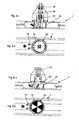
- FIG. 4.1 The following Figures 4.1, 4.2, 5.1, 5.2, 6.1 and 6.2 , Show spray arms 7, in which the closure member 20 rotates in its operative position at a speed which differs from the rotational speed of the spray arm 7.
- the in the Figures 4.1 and 4.2 illustrated spray arm 7 is coupled to a holder 6, which is provided with different polarized magnets 30 and 31.
- an axis 25 connected to the closure element 20 extends into the region of these magnets 30 and 31. It carries on the end of this axis 25 crosswise arranged magnets 32 and 33, which are also differently poled.
- the closure element 20 itself is rotatably mounted within the receiving space 14 by means described elsewhere.
- the closure element is rotated by an electric motor.
- FIGS. 5.1 and 5.2 show spray arm variants in which the closure element 20 is also rotatably mounted in the receiving space. There, the element 20 is rotated by means of turbine blades 40 and 50, respectively.
- This has the advantage that a rotational movement is caused by the liquid flowing through 18 and thus no further, wear-prone drives are required.
- the rotational speed in addition to the flow rate of the dimensioning of the turbine blades 40 and 50 depends and can be chosen so that it differs from the speed of the spray arm 7.
- the direction of inclination of the turbine blades 40 and 50 is designed so that adjusts to the spray arm 7 opposite direction of rotation.
- the vanes 40 may be disposed on a shaft 26 that extends through the center of the closure member 20, see FIGS. 51 and 5.2.
- the shaft 26 must be stored, which requires additional effort and can lead to blocking due to a possible tilting movement of the overall arrangement. It is therefore more advantageous if the turbine blades 50, as in the Figures 6.1 and 6.2 are placed inside the closure element 20. They can then be formed on the closure element 20, which on the one hand simplifies the production, on the other hand, the necessary receiving space for the element is kept low.
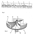
- FIGS. 7 show various, designated by a to f closure elements that differ in terms of the number of openings and their shape and size.
- the element designated by a has four openings and consequently also four sealing surfaces, two of which are opposite each other.
- a simultaneous blocking of all spray nozzles is achieved.
- the closure element designated b three openings or closure surfaces are provided. The symmetrical arrangement ensures that in a spray arm 7 with two halves only one half is locked.
- Element c shows a variant with relatively small openings, in the closure elements according to d and e, the openings have approximately the same width as the closure surfaces, f shows an element with very narrow closure surfaces.
- the closure elements c and e with round or elliptical openings differ from the elements d and f with rectangular openings.
- FIG. 8 shows a closure element 60, which is optimized in terms of its geometric relationships. It is designed as a one-piece component and preferably made of plastic.
- a stub shaft 62 is formed on a plate-shaped bottom part 61 in the axis of rotation, which in a bore (not shown) in the center of the receiving space 14 (see FIG. 1 ) is used.
- the bore acts as a sliding bearing, thereby reducing the static friction between the closure member 60 and spray arm 7 and the rotation of the element 60 is made possible in the first place.
- On the opposite side of the bottom part of the stub shaft 62 is continued with reduced diameter as removal pin 63, thus facilitating the installation and the subsequent removal.
- three symmetrically arranged bodies 64 rise from the edge of the bottom part 61 and form both the closing surfaces 65 and the oblique turbine blades 66 required for driving. Between the closure surfaces openings 67 are left with a rectangular cross-section, the arc length of the closure surfaces 65 and the openings 67 is approximately equal and is about 60 °.
Landscapes
- Washing And Drying Of Tableware (AREA)
- Nozzles (AREA)
Claims (11)
- Lave-linge (1), avec une cuve de lavage (2) dans laquelle au moins un dispositif de pulvérisation (7) équipé de buses de pulvérisation (8) est supporté en rotation autour d'un axe (17) au moins approximativement vertical dans la position d'utilisation du lave-linge, avec des moyens (9, 10) pour alimenter en liquide de lavage (18) le dispositif de pulvérisation (7) ou respectivement les buses de pulvérisation (8), des moyens rotatifs étant prévus dans le dispositif de pulvérisation (7) et provoquant une fermeture et une ouverture de buses de pulvérisation (8) pour réaliser des jets de pulvérisation pulsés,
caractérisé en ce que
les moyens sont disposés dans la zone de l'axe de rotation (17) du dispositif de pulvérisation (7) et peuvent tourner dans le plan du dispositif de pulvérisation (7) avec une vitesse de rotation différente par rapport au dispositif de pulvérisation (7), et en ce que les moyens comprennent au moins un élément de fermeture (20, 60) essentiellement cylindrique avec des orifices (21, 67) disposés dans son enveloppe de cylindre, l'axe de cylindre coïncidant avec l'axe de rotation (17). - Lave-linge (1) selon la revendication 1,
caractérisé en ce que
les orifices (21, 67) dans l'enveloppe de cylindre de l'élément de fermeture (20, 60) sont positionnés de telle sorte par rapport à des conduits (15, 16) raccordés aux buses de pulvérisation (8) que, pendant une rotation relative entre l'élément de fermeture (20, 60) et le dispositif de pulvérisation (7), seul le chemin du liquide de lavage (18) vers un nombre partiel de conduits (15, 16) est interrompu. - Lave-linge (1) selon la revendication 2,
caractérisé en ce que
le dispositif de pulvérisation est réalisé en tant que bras de pulvérisation (7) avec deux moitiés de bras de pulvérisation (70, 71), et en ce que l'élément de fermeture (20, 60) possède un nombre impair de surfaces de fermeture (22, 65), en particulier trois. - Lave-linge (1) selon au moins une des revendications 1 à 3,
caractérisé en ce que
l'élément de fermeture (20, 60) est entraîné par moteur électrique. - Lave-linge (1) selon au moins une des revendications 1 à 3,
caractérisé en ce que
l'élément de fermeture (20, 60) est entraîné par au moins un aimant (30 à 33). - Lave-linge (1) selon au moins une des revendications 1 à 3,
caractérisé en ce que
l'élément de fermeture (20, 60) est mis en rotation par le liquide de lavage (18) s'écoulant vers les buses de pulvérisation (8). - Lave-linge (1) selon la revendication 6,
caractérisé en ce que
l'élément de fermeture (20, 60) est entraîné par une turbine (40, 50, 66). - Lave-linge (1) selon la revendication 7,
caractérisé en ce que
les aubes de turbine (40) sont disposées sur un arbre (26) s'étendant à travers le centre de l'élément de fermeture (20). - Lave-linge (1) selon la revendication 7,
caractérisé en ce que
les aubes de turbine (50, 66) sont disposées à l'intérieur de l'élément de fermeture (20, 60). - Lave-linge (1) selon la revendication 7,
caractérisé en ce que
l'élément de fermeture (20, 60) est supporté d'un côté. - Lave-linge (1) selon la revendication 9 ou 10,
caractérisé en ce
qu'un bout d'arbre (62) disposé sur l'élément de fermeture est guidé dans un palier lisse disposé dans le centre (17) du dispositif de pulvérisation (7).
Priority Applications (1)
| Application Number | Priority Date | Filing Date | Title |
|---|---|---|---|
| PL06009112T PL1731081T3 (pl) | 2005-06-08 | 2006-05-03 | Zmywarka do naczyń |
Applications Claiming Priority (2)
| Application Number | Priority Date | Filing Date | Title |
|---|---|---|---|
| DE200510026558 DE102005026558B3 (de) | 2005-06-08 | 2005-06-08 | Geschirrspülmaschine mit einem Spülbehälter in dem wenigstens ein Sprüharm angeordnet ist |
| DE200610012080 DE102006012080A1 (de) | 2006-03-14 | 2006-03-14 | Spülmaschine |
Publications (4)
| Publication Number | Publication Date |
|---|---|
| EP1731081A2 EP1731081A2 (fr) | 2006-12-13 |
| EP1731081A3 EP1731081A3 (fr) | 2007-01-03 |
| EP1731081B1 EP1731081B1 (fr) | 2008-06-25 |
| EP1731081B2 true EP1731081B2 (fr) | 2013-07-10 |
Family
ID=36941987
Family Applications (1)
| Application Number | Title | Priority Date | Filing Date |
|---|---|---|---|
| EP06009112.1A Expired - Lifetime EP1731081B2 (fr) | 2005-06-08 | 2006-05-03 | Lave-vaisselle |
Country Status (6)
| Country | Link |
|---|---|
| US (1) | US20060278258A1 (fr) |
| EP (1) | EP1731081B2 (fr) |
| AT (1) | ATE398962T1 (fr) |
| DE (1) | DE502006000969D1 (fr) |
| ES (1) | ES2306324T3 (fr) |
| PL (1) | PL1731081T3 (fr) |
Families Citing this family (65)
| Publication number | Priority date | Publication date | Assignee | Title |
|---|---|---|---|---|
| DE102006021954B3 (de) * | 2006-05-10 | 2007-09-13 | Miele & Cie. Kg | Verfahren zur Durchführung eines Spülprogramms in einer Spülmaschine |
| KR20080053981A (ko) * | 2006-12-12 | 2008-06-17 | 엘지전자 주식회사 | 식기 세척기 |
| EP2192852B1 (fr) * | 2007-08-14 | 2011-09-14 | Miele & Cie. KG | Lave-vaisselle |
| US7896977B2 (en) * | 2007-12-19 | 2011-03-01 | Whirlpool Corporation | Dishwasher with sequencing corner nozzles |
| US8166983B2 (en) * | 2007-12-21 | 2012-05-01 | Wolf Appliance, Inc. | Fluid supply system for appliance |
| DE102008015968A1 (de) * | 2008-03-20 | 2009-09-24 | Hansgrohe Ag | Brausekopf |
| US8113222B2 (en) * | 2008-12-16 | 2012-02-14 | Whirlpool Corporation | Dishwasher with driven spray arm for upper rack |
| US8347898B2 (en) * | 2009-04-30 | 2013-01-08 | Whirlpool Corporation | Dishwasher with rotating zone wash sprayers |
| US9119521B2 (en) | 2010-06-09 | 2015-09-01 | Whirlpool Corporation | Spray assembly for a dishwasher |
| US8852351B2 (en) * | 2010-10-20 | 2014-10-07 | Whirlpool Corporation | Dishwasher with wash load detection |
| US8834648B2 (en) * | 2010-10-21 | 2014-09-16 | Whirlpool Corporation | Dishwasher with controlled rotation of lower spray arm |
| DE102010043462A1 (de) * | 2010-11-05 | 2012-05-10 | BSH Bosch und Siemens Hausgeräte GmbH | Geschirrspülmaschine mit zumindest einem rotierbaren Sprüharm |
| US9492055B2 (en) | 2011-09-22 | 2016-11-15 | Whirlpool Corporation | Dishwasher with spray system |
| US9375128B2 (en) | 2011-09-22 | 2016-06-28 | Whirlpool Corporation | Dishwasher with spray system |
| US9414736B2 (en) | 2011-09-22 | 2016-08-16 | Whirlpool Corporation | Dishwasher with directional spray |
| US9693672B2 (en) | 2011-09-22 | 2017-07-04 | Whirlpool Corporation | Dishwasher with sprayer |
| EP2572624B8 (fr) * | 2011-09-22 | 2018-02-07 | Whirlpool Corporation | Lave-vaisselle avec système de pulvérisation |
| KR101860717B1 (ko) * | 2012-01-06 | 2018-05-24 | 삼성전자주식회사 | 노즐 어셈블리와 이를 구비한 식기 세척기 |
| KR101909028B1 (ko) * | 2012-04-23 | 2018-10-17 | 엘지전자 주식회사 | 식기세척기 |
| US9295368B2 (en) | 2013-03-01 | 2016-03-29 | Whirlpool Corporation | Dishwasher with hydraulically driven sprayer |
| US9532701B2 (en) | 2013-03-01 | 2017-01-03 | Whirlpool Corporation | Dishwasher with sprayer |
| US9713413B2 (en) | 2013-07-01 | 2017-07-25 | Whirlpool Corporation | Dishwasher for treating dishes |
| US9532699B2 (en) * | 2013-07-15 | 2017-01-03 | Whirlpool Corporation | Dishwasher with sprayer |
| KR102306964B1 (ko) * | 2013-12-31 | 2021-10-01 | 삼성전자주식회사 | 식기 세척기 |
| US10221952B2 (en) * | 2013-12-31 | 2019-03-05 | Samsung Electronics Co., Ltd. | Dish washing machine |
| US9736123B2 (en) | 2015-01-14 | 2017-08-15 | Haier Us Appliance Solutions, Inc. | Spray arm assemblies for dishwasher appliances |
| US9801523B2 (en) | 2014-08-27 | 2017-10-31 | Haier Us Appliance Solutions, Inc. | Spray device assembly for dishwasher appliance |
| US20160198927A1 (en) * | 2015-01-14 | 2016-07-14 | General Electric Company | Spray arm assemblies for dishwasher appliances |
| US9931015B2 (en) | 2015-01-27 | 2018-04-03 | Whirlpool Corporation | Hydraulically-driven dishwasher diverters |
| WO2016169303A1 (fr) * | 2015-04-22 | 2016-10-27 | 佛山市顺德区美的洗涤电器制造有限公司 | Ensemble bras de pulvérisation pour lave-vaisselle et lave-vaisselle comprenant ce dernier |
| DE102015222771B3 (de) | 2015-11-18 | 2017-05-18 | Technische Universität Berlin | Fluidisches Bauteil |
| CN205393066U (zh) | 2016-03-07 | 2016-07-27 | 成都京东方光电科技有限公司 | 喷淋设备 |
| TR201706566A3 (tr) * | 2017-05-04 | 2018-12-21 | Arcelik As | Bi̇r su püskürtme başliği i̇çeren bi̇r bulaşik maki̇nesi̇ |
| CN107115079B (zh) * | 2017-07-16 | 2019-07-12 | 宁波凯瑞博人力资源管理服务有限公司 | 一种用于洗碗机的可自动更换方向的喷淋头及其洗碗机 |
| CN109394117B (zh) * | 2017-08-18 | 2024-02-20 | 宁波方太厨具有限公司 | 一种喷淋臂及应用有该喷淋臂的清洗机 |
| US10524634B2 (en) | 2017-09-29 | 2020-01-07 | Midea Group Co., Ltd. | Dishwasher with combined liquid and air sprayers |
| US10531781B2 (en) | 2017-09-29 | 2020-01-14 | Midea Group Co., Ltd. | Dishwasher with discretely directable tubular spray elements |
| US12290225B2 (en) | 2017-09-29 | 2025-05-06 | Midea Group Co., Ltd. | Dishwasher with walking tubular spray element |
| CN108464805B (zh) * | 2018-04-17 | 2024-06-25 | 宁波欧琳科技股份有限公司 | 一种增压型脉冲清洗设备 |
| CN108403046B (zh) * | 2018-04-23 | 2024-08-06 | 宁波欧琳科技股份有限公司 | 一种洗碗机脉冲式喷淋设备 |
| CN108720769B (zh) * | 2018-04-23 | 2024-08-27 | 宁波欧琳科技股份有限公司 | 一种脉冲式空气注入喷淋设备 |
| CN110664347B (zh) * | 2018-07-02 | 2023-04-18 | 青岛海尔洗碗机有限公司 | 一种洗碗机的喷淋装置 |
| US10631708B2 (en) | 2018-09-14 | 2020-04-28 | Midea Group Co., Ltd. | Dishwasher with docking arrangement for elevation-adjustable rack |
| US10765291B2 (en) | 2018-09-14 | 2020-09-08 | Midea Group Co., Ltd. | Dishwasher with check valve in rotatable docking port |
| US11071440B2 (en) | 2018-09-14 | 2021-07-27 | Midea Group Co., Ltd. | Dishwasher with rack-mounted conduit return mechanism |
| US11000176B2 (en) | 2018-09-14 | 2021-05-11 | Midea Group Co., Ltd. | Dishwasher with rotatable diverter valve |
| CN112638228B (zh) * | 2018-09-26 | 2024-07-05 | 罗德电工有限公司 | 用于管理特别是诸如洗衣机、洗碗机或类似电器的家用电器中的液体的流动的分流器设备 |
| US11045066B2 (en) | 2019-03-11 | 2021-06-29 | Midea Group Co., Ltd. | Dishwasher with keyed coupling to rack-mounted conduit |
| WO2020251501A1 (fr) * | 2019-06-14 | 2020-12-17 | Arcelik Anonim Sirketi | Lave-vaisselle à performance de lavage améliorée |
| US11399690B2 (en) | 2019-09-30 | 2022-08-02 | Midea Group Co., Ltd. | Dishwasher with cam-based position sensor |
| US11259681B2 (en) | 2019-09-30 | 2022-03-01 | Midea Group Co., Ltd | Dishwasher with image-based diagnostics |
| US11026559B2 (en) | 2019-09-30 | 2021-06-08 | Midea Group Co., Ltd. | Dishwasher with image-based fluid condition sensing |
| US11191416B2 (en) | 2019-09-30 | 2021-12-07 | Midea Group Co., Ltd. | Dishwasher with image-based position sensor |
| US11484183B2 (en) | 2019-09-30 | 2022-11-01 | Midea Group Co., Ltd. | Dishwasher with image-based object sensing |
| US11464389B2 (en) | 2019-09-30 | 2022-10-11 | Midea Group Co., Ltd. | Dishwasher with image-based detergent sensing |
| US11202550B2 (en) | 2019-11-20 | 2021-12-21 | Midea Group Co., Ltd. | Dishwasher thermal imaging system |
| US11185209B2 (en) | 2019-11-20 | 2021-11-30 | Midea Group Co., Ltd. | Dishwasher steam generator |
| US11497374B2 (en) | 2020-02-19 | 2022-11-15 | Midea Group Co., Ltd. | Dishwasher with wall-mounted rotatable conduit |
| US11412912B2 (en) | 2020-09-21 | 2022-08-16 | Midea Group Co., Ltd. | Dishwasher with tubular spray element slip ring alignment |
| US11484180B2 (en) | 2020-11-11 | 2022-11-01 | Midea Group Co., Ltd. | Dishwasher with tubular spray element including multiple selectable spray patterns |
| CN114424920B (zh) * | 2022-01-12 | 2024-03-19 | 江苏大学 | 一种安装脉冲式喷淋臂的洗碗机 |
| US11826001B2 (en) | 2022-02-15 | 2023-11-28 | Midea Group Co., Ltd. | Dishwasher with tubular spray element including elongated metal tube and retaining tab for mounting support member thereto |
| US12245735B2 (en) | 2022-02-25 | 2025-03-11 | Midea Group Co., Ltd. | Dishwasher including tubular spray element with intermediate support and/or fluid inlet |
| CN117770723A (zh) | 2022-09-22 | 2024-03-29 | 泰科电子(上海)有限公司 | 用于检测家电设备喷淋臂转动的结构以及家电设备 |
| US12329341B2 (en) | 2023-06-28 | 2025-06-17 | Midea Group Co., Ltd. | Dishwasher with rack-mounted tubular spray element assembly |
Citations (4)
| Publication number | Priority date | Publication date | Assignee | Title |
|---|---|---|---|---|
| DE3426004A1 (de) † | 1983-07-20 | 1985-01-31 | General Electric Co., Schenectady, N.Y. | Geschirrspuelmaschine |
| US4884585A (en) † | 1988-10-21 | 1989-12-05 | Oh Yang H | Rotary sprayer for an automatic dishwasher |
| US5655556A (en) † | 1994-06-16 | 1997-08-12 | Electrolux Zanussi Elettrodomestici S.P.A. | Dishwasher with rotating spray agitator |
| EP0974302A2 (fr) † | 1998-07-22 | 2000-01-26 | Premark FEG L.L.C. | Dispositif de rincage pour lave-vaisselle |
Family Cites Families (14)
| Publication number | Priority date | Publication date | Assignee | Title |
|---|---|---|---|---|
| DE1403671A1 (de) | 1960-08-04 | 1968-10-24 | Siemens Elektorgeraete Gmbh | Geschirrspuele |
| US3115306A (en) * | 1962-11-07 | 1963-12-24 | Lewis A James | Liquid distributor for dishwashing machines |
| US3473736A (en) * | 1967-09-13 | 1969-10-21 | Charles J Heitzman | Pulsating device for water outlet fixtures |
| US3678957A (en) * | 1969-10-14 | 1972-07-25 | Sven Gustaf Nord | Dishwasher device causing an aperiodical water flow |
| US3941139A (en) * | 1974-08-15 | 1976-03-02 | Whirlpool Corporation | Dishwasher spray assembly with intermittently operating nozzles |
| US4145002A (en) * | 1977-01-31 | 1979-03-20 | Noren Tore H | Rotary spray manifold |
| IT1143342B (it) * | 1981-02-02 | 1986-10-22 | Indesit | Dispositivo commutatore automatico per l alimentazione dei collettori rotanti di una macchina lavastoviglie |
| US4802508A (en) * | 1988-03-31 | 1989-02-07 | Pacific Biosystems, Inc. | Cyclically varying pulsating fluid supply system |
| IT1268535B1 (it) | 1993-12-20 | 1997-03-04 | Zanussi Elettrodomestici | Programma operativo per macchina lavastoviglie |
| DE19630327A1 (de) * | 1996-07-26 | 1998-01-29 | Juno Groskuechen Gmbh | Verteiler |
| DE19812231A1 (de) | 1998-03-20 | 1999-09-23 | Aeg Hausgeraete Gmbh | Geschirrspülmaschine |
| IT1311214B1 (it) * | 1999-03-29 | 2002-03-04 | Electrolux Zanussi Elettrodome | Lavastoviglie con getti d'acqua pulsanti |
| CN1187017C (zh) * | 2000-02-14 | 2005-02-02 | 松下电器产业株式会社 | 清洗机 |
| DE10151864B4 (de) * | 2001-10-24 | 2006-01-26 | Boll & Kirch Filterbau Gmbh | Verfahren zum Betrieb eines Filters für Flüssigkeiten und System zur Durchführung des Verfahrens |
-
2006
- 2006-05-03 DE DE502006000969T patent/DE502006000969D1/de not_active Expired - Lifetime
- 2006-05-03 PL PL06009112T patent/PL1731081T3/pl unknown
- 2006-05-03 AT AT06009112T patent/ATE398962T1/de not_active IP Right Cessation
- 2006-05-03 ES ES06009112T patent/ES2306324T3/es not_active Expired - Lifetime
- 2006-05-03 EP EP06009112.1A patent/EP1731081B2/fr not_active Expired - Lifetime
- 2006-06-07 US US11/422,733 patent/US20060278258A1/en not_active Abandoned
Patent Citations (4)
| Publication number | Priority date | Publication date | Assignee | Title |
|---|---|---|---|---|
| DE3426004A1 (de) † | 1983-07-20 | 1985-01-31 | General Electric Co., Schenectady, N.Y. | Geschirrspuelmaschine |
| US4884585A (en) † | 1988-10-21 | 1989-12-05 | Oh Yang H | Rotary sprayer for an automatic dishwasher |
| US5655556A (en) † | 1994-06-16 | 1997-08-12 | Electrolux Zanussi Elettrodomestici S.P.A. | Dishwasher with rotating spray agitator |
| EP0974302A2 (fr) † | 1998-07-22 | 2000-01-26 | Premark FEG L.L.C. | Dispositif de rincage pour lave-vaisselle |
Also Published As
| Publication number | Publication date |
|---|---|
| EP1731081A2 (fr) | 2006-12-13 |
| EP1731081B1 (fr) | 2008-06-25 |
| EP1731081A3 (fr) | 2007-01-03 |
| ES2306324T3 (es) | 2008-11-01 |
| US20060278258A1 (en) | 2006-12-14 |
| DE502006000969D1 (de) | 2008-08-07 |
| ATE398962T1 (de) | 2008-07-15 |
| PL1731081T3 (pl) | 2008-09-30 |
Similar Documents
| Publication | Publication Date | Title |
|---|---|---|
| EP1731081B1 (fr) | Lave-vaisselle | |
| DE19832982C2 (de) | Spülvorrichtung für eine Geschirrspülmaschine | |
| DE2621307A1 (de) | Verfahren und vorrichtung zur reinigung eines fluessigkeitsfilters | |
| DE3511314A1 (de) | Brausekopf zum erzeugen eines pulsierenden strahls | |
| DE10111533A1 (de) | Geschirrspülmaschine mit einer drehbar gelagerten Sprüheinrichtung und Steuerverfahren hierfür | |
| DE29509718U1 (de) | Geschirrspüler mit drehendem Sprüharm | |
| DE102005026558B3 (de) | Geschirrspülmaschine mit einem Spülbehälter in dem wenigstens ein Sprüharm angeordnet ist | |
| DE3019601C2 (de) | Lebensmittel-Waschmaschine mit Trocknungseinrichtung | |
| DD296861A5 (de) | Duesenanordnung zur innenspritzung von flanken | |
| DE102009007297A1 (de) | Spülautomat mit einem quaderförmigen Spülraum | |
| DE202012104534U1 (de) | Zylindrische Filterkerze und Rückspülfilter hiermit | |
| DE102006012080A1 (de) | Spülmaschine | |
| DE1920575B2 (de) | Spritzeinrichtung fuer geschirrspuelmaschinen | |
| EP4003126B1 (fr) | Lave-vaisselle domestique | |
| EP3777639B1 (fr) | Appareil électroménager à circulation d'eau et procédé de fonctionnement d'un appareil électroménager à circulation d'eau | |
| DE2826735C3 (de) | Einrichtung für eine Geschirrspülmaschine | |
| DE3306003C2 (de) | Filtereinrichtung für die mechanische Reinigung eines Kühlwasserstromes von Kraftwerkskondensatoranlagen | |
| DE102007029701B4 (de) | Waschsystem für eine Geschirrspülmaschine sowie Geschirrspülmaschine | |
| DE102012104026A1 (de) | Spülsystem für Geschirrspülmaschinen, sowie Geschirrspülmaschine mit einem solchen Spülsystem | |
| AT222840B (de) | Geschirrspülmaschine | |
| EP1715965B1 (fr) | Dispositif de nettoyage a jet oscillant comportant un entrainement oscillant ne faisant pas appel a une energie exterieure | |
| DE1191527B (de) | Geschirrspuelmaschine | |
| DE69314133T2 (de) | Verstellbare Düse für Waschmitteleinspülbehälter | |
| CH648767A5 (en) | Mixing unit | |
| DE2313980A1 (de) | Waschanlage fuer fahrzeugscheiben, insbesondere abdeckscheiben von kraftfahrzeugleuchten |
Legal Events
| Date | Code | Title | Description |
|---|---|---|---|
| PUAI | Public reference made under article 153(3) epc to a published international application that has entered the european phase |
Free format text: ORIGINAL CODE: 0009012 |
|
| PUAL | Search report despatched |
Free format text: ORIGINAL CODE: 0009013 |
|
| AK | Designated contracting states |
Kind code of ref document: A2 Designated state(s): AT BE BG CH CY CZ DE DK EE ES FI FR GB GR HU IE IS IT LI LT LU LV MC NL PL PT RO SE SI SK TR |
|
| AX | Request for extension of the european patent |
Extension state: AL BA HR MK YU |
|
| AK | Designated contracting states |
Kind code of ref document: A3 Designated state(s): AT BE BG CH CY CZ DE DK EE ES FI FR GB GR HU IE IS IT LI LT LU LV MC NL PL PT RO SE SI SK TR |
|
| AX | Request for extension of the european patent |
Extension state: AL BA HR MK YU |
|
| 17P | Request for examination filed |
Effective date: 20070503 |
|
| AKX | Designation fees paid |
Designated state(s): AT BE BG CH CY CZ DE DK EE ES FI FR GB GR HU IE IS IT LI LT LU LV MC NL PL PT RO SE SI SK TR |
|
| GRAP | Despatch of communication of intention to grant a patent |
Free format text: ORIGINAL CODE: EPIDOSNIGR1 |
|
| RTI1 | Title (correction) |
Free format text: DISHWASHER |
|
| GRAS | Grant fee paid |
Free format text: ORIGINAL CODE: EPIDOSNIGR3 |
|
| GRAA | (expected) grant |
Free format text: ORIGINAL CODE: 0009210 |
|
| AK | Designated contracting states |
Kind code of ref document: B1 Designated state(s): AT BE BG CH CY CZ DE DK EE ES FI FR GB GR HU IE IS IT LI LT LU LV MC NL PL PT RO SE SI SK TR |
|
| REG | Reference to a national code |
Ref country code: GB Ref legal event code: FG4D Free format text: NOT ENGLISH |
|
| REG | Reference to a national code |
Ref country code: CH Ref legal event code: EP |
|
| REF | Corresponds to: |
Ref document number: 502006000969 Country of ref document: DE Date of ref document: 20080807 Kind code of ref document: P |
|
| REG | Reference to a national code |
Ref country code: GB Ref legal event code: 746 Effective date: 20080718 |
|
| REG | Reference to a national code |
Ref country code: IE Ref legal event code: FG4D Free format text: LANGUAGE OF EP DOCUMENT: GERMAN |
|
| REG | Reference to a national code |
Ref country code: PL Ref legal event code: T3 |
|
| PG25 | Lapsed in a contracting state [announced via postgrant information from national office to epo] |
Ref country code: SI Free format text: LAPSE BECAUSE OF FAILURE TO SUBMIT A TRANSLATION OF THE DESCRIPTION OR TO PAY THE FEE WITHIN THE PRESCRIBED TIME-LIMIT Effective date: 20080625 Ref country code: FI Free format text: LAPSE BECAUSE OF FAILURE TO SUBMIT A TRANSLATION OF THE DESCRIPTION OR TO PAY THE FEE WITHIN THE PRESCRIBED TIME-LIMIT Effective date: 20080625 |
|
| REG | Reference to a national code |
Ref country code: ES Ref legal event code: FG2A Ref document number: 2306324 Country of ref document: ES Kind code of ref document: T3 |
|
| PG25 | Lapsed in a contracting state [announced via postgrant information from national office to epo] |
Ref country code: NL Free format text: LAPSE BECAUSE OF FAILURE TO SUBMIT A TRANSLATION OF THE DESCRIPTION OR TO PAY THE FEE WITHIN THE PRESCRIBED TIME-LIMIT Effective date: 20080625 Ref country code: LV Free format text: LAPSE BECAUSE OF FAILURE TO SUBMIT A TRANSLATION OF THE DESCRIPTION OR TO PAY THE FEE WITHIN THE PRESCRIBED TIME-LIMIT Effective date: 20080625 |
|
| NLV1 | Nl: lapsed or annulled due to failure to fulfill the requirements of art. 29p and 29m of the patents act | ||
| PG25 | Lapsed in a contracting state [announced via postgrant information from national office to epo] |
Ref country code: SE Free format text: LAPSE BECAUSE OF FAILURE TO SUBMIT A TRANSLATION OF THE DESCRIPTION OR TO PAY THE FEE WITHIN THE PRESCRIBED TIME-LIMIT Effective date: 20080925 Ref country code: LT Free format text: LAPSE BECAUSE OF FAILURE TO SUBMIT A TRANSLATION OF THE DESCRIPTION OR TO PAY THE FEE WITHIN THE PRESCRIBED TIME-LIMIT Effective date: 20080625 Ref country code: IS Free format text: LAPSE BECAUSE OF FAILURE TO SUBMIT A TRANSLATION OF THE DESCRIPTION OR TO PAY THE FEE WITHIN THE PRESCRIBED TIME-LIMIT Effective date: 20081025 Ref country code: CZ Free format text: LAPSE BECAUSE OF FAILURE TO SUBMIT A TRANSLATION OF THE DESCRIPTION OR TO PAY THE FEE WITHIN THE PRESCRIBED TIME-LIMIT Effective date: 20080625 |
|
| PG25 | Lapsed in a contracting state [announced via postgrant information from national office to epo] |
Ref country code: RO Free format text: LAPSE BECAUSE OF FAILURE TO SUBMIT A TRANSLATION OF THE DESCRIPTION OR TO PAY THE FEE WITHIN THE PRESCRIBED TIME-LIMIT Effective date: 20080625 Ref country code: PT Free format text: LAPSE BECAUSE OF FAILURE TO SUBMIT A TRANSLATION OF THE DESCRIPTION OR TO PAY THE FEE WITHIN THE PRESCRIBED TIME-LIMIT Effective date: 20081125 Ref country code: SK Free format text: LAPSE BECAUSE OF FAILURE TO SUBMIT A TRANSLATION OF THE DESCRIPTION OR TO PAY THE FEE WITHIN THE PRESCRIBED TIME-LIMIT Effective date: 20080625 |
|
| REG | Reference to a national code |
Ref country code: IE Ref legal event code: FD4D |
|
| PLBI | Opposition filed |
Free format text: ORIGINAL CODE: 0009260 |
|
| PG25 | Lapsed in a contracting state [announced via postgrant information from national office to epo] |
Ref country code: IE Free format text: LAPSE BECAUSE OF FAILURE TO SUBMIT A TRANSLATION OF THE DESCRIPTION OR TO PAY THE FEE WITHIN THE PRESCRIBED TIME-LIMIT Effective date: 20080625 Ref country code: BG Free format text: LAPSE BECAUSE OF FAILURE TO SUBMIT A TRANSLATION OF THE DESCRIPTION OR TO PAY THE FEE WITHIN THE PRESCRIBED TIME-LIMIT Effective date: 20080925 Ref country code: DK Free format text: LAPSE BECAUSE OF FAILURE TO SUBMIT A TRANSLATION OF THE DESCRIPTION OR TO PAY THE FEE WITHIN THE PRESCRIBED TIME-LIMIT Effective date: 20080625 Ref country code: EE Free format text: LAPSE BECAUSE OF FAILURE TO SUBMIT A TRANSLATION OF THE DESCRIPTION OR TO PAY THE FEE WITHIN THE PRESCRIBED TIME-LIMIT Effective date: 20080625 |
|
| 26 | Opposition filed |
Opponent name: AEG HAUSGERAETE GMBH Effective date: 20090325 |
|
| PLAX | Notice of opposition and request to file observation + time limit sent |
Free format text: ORIGINAL CODE: EPIDOSNOBS2 |
|
| PLBB | Reply of patent proprietor to notice(s) of opposition received |
Free format text: ORIGINAL CODE: EPIDOSNOBS3 |
|
| BERE | Be: lapsed |
Owner name: MIELE & CIE. K.G. Effective date: 20090531 |
|
| PG25 | Lapsed in a contracting state [announced via postgrant information from national office to epo] |
Ref country code: MC Free format text: LAPSE BECAUSE OF NON-PAYMENT OF DUE FEES Effective date: 20090531 |
|
| RDAF | Communication despatched that patent is revoked |
Free format text: ORIGINAL CODE: EPIDOSNREV1 |
|
| PLBP | Opposition withdrawn |
Free format text: ORIGINAL CODE: 0009264 |
|
| APBM | Appeal reference recorded |
Free format text: ORIGINAL CODE: EPIDOSNREFNO |
|
| APBP | Date of receipt of notice of appeal recorded |
Free format text: ORIGINAL CODE: EPIDOSNNOA2O |
|
| APAH | Appeal reference modified |
Free format text: ORIGINAL CODE: EPIDOSCREFNO |
|
| PG25 | Lapsed in a contracting state [announced via postgrant information from national office to epo] |
Ref country code: BE Free format text: LAPSE BECAUSE OF NON-PAYMENT OF DUE FEES Effective date: 20090531 |
|
| PG25 | Lapsed in a contracting state [announced via postgrant information from national office to epo] |
Ref country code: AT Free format text: LAPSE BECAUSE OF NON-PAYMENT OF DUE FEES Effective date: 20090503 |
|
| PGFP | Annual fee paid to national office [announced via postgrant information from national office to epo] |
Ref country code: IT Payment date: 20100526 Year of fee payment: 5 Ref country code: PL Payment date: 20100428 Year of fee payment: 5 |
|
| APBQ | Date of receipt of statement of grounds of appeal recorded |
Free format text: ORIGINAL CODE: EPIDOSNNOA3O |
|
| PG25 | Lapsed in a contracting state [announced via postgrant information from national office to epo] |
Ref country code: GR Free format text: LAPSE BECAUSE OF FAILURE TO SUBMIT A TRANSLATION OF THE DESCRIPTION OR TO PAY THE FEE WITHIN THE PRESCRIBED TIME-LIMIT Effective date: 20080926 |
|
| PGFP | Annual fee paid to national office [announced via postgrant information from national office to epo] |
Ref country code: TR Payment date: 20100422 Year of fee payment: 5 |
|
| REG | Reference to a national code |
Ref country code: CH Ref legal event code: PL |
|
| PG25 | Lapsed in a contracting state [announced via postgrant information from national office to epo] |
Ref country code: CH Free format text: LAPSE BECAUSE OF NON-PAYMENT OF DUE FEES Effective date: 20100531 Ref country code: LI Free format text: LAPSE BECAUSE OF NON-PAYMENT OF DUE FEES Effective date: 20100531 |
|
| PG25 | Lapsed in a contracting state [announced via postgrant information from national office to epo] |
Ref country code: LU Free format text: LAPSE BECAUSE OF NON-PAYMENT OF DUE FEES Effective date: 20090503 |
|
| PG25 | Lapsed in a contracting state [announced via postgrant information from national office to epo] |
Ref country code: HU Free format text: LAPSE BECAUSE OF FAILURE TO SUBMIT A TRANSLATION OF THE DESCRIPTION OR TO PAY THE FEE WITHIN THE PRESCRIBED TIME-LIMIT Effective date: 20081226 |
|
| REG | Reference to a national code |
Ref country code: PL Ref legal event code: LICE Effective date: 20101122 |
|
| PG25 | Lapsed in a contracting state [announced via postgrant information from national office to epo] |
Ref country code: CY Free format text: LAPSE BECAUSE OF FAILURE TO SUBMIT A TRANSLATION OF THE DESCRIPTION OR TO PAY THE FEE WITHIN THE PRESCRIBED TIME-LIMIT Effective date: 20080625 |
|
| PG25 | Lapsed in a contracting state [announced via postgrant information from national office to epo] |
Ref country code: IT Free format text: LAPSE BECAUSE OF NON-PAYMENT OF DUE FEES Effective date: 20110503 |
|
| APBU | Appeal procedure closed |
Free format text: ORIGINAL CODE: EPIDOSNNOA9O |
|
| PG25 | Lapsed in a contracting state [announced via postgrant information from national office to epo] |
Ref country code: PL Free format text: LAPSE BECAUSE OF NON-PAYMENT OF DUE FEES Effective date: 20110503 |
|
| REG | Reference to a national code |
Ref country code: PL Ref legal event code: LAPE |
|
| PGFP | Annual fee paid to national office [announced via postgrant information from national office to epo] |
Ref country code: ES Payment date: 20120525 Year of fee payment: 7 |
|
| PUAH | Patent maintained in amended form |
Free format text: ORIGINAL CODE: 0009272 |
|
| STAA | Information on the status of an ep patent application or granted ep patent |
Free format text: STATUS: PATENT MAINTAINED AS AMENDED |
|
| 27A | Patent maintained in amended form |
Effective date: 20130710 |
|
| AK | Designated contracting states |
Kind code of ref document: B2 Designated state(s): AT BE BG CH CY CZ DE DK EE ES FI FR GB GR HU IE IS IT LI LT LU LV MC NL PL PT RO SE SI SK TR |
|
| REG | Reference to a national code |
Ref country code: DE Ref legal event code: R102 Ref document number: 502006000969 Country of ref document: DE Effective date: 20130710 |
|
| PG25 | Lapsed in a contracting state [announced via postgrant information from national office to epo] |
Ref country code: TR Free format text: LAPSE BECAUSE OF NON-PAYMENT OF DUE FEES Effective date: 20110503 |
|
| PG25 | Lapsed in a contracting state [announced via postgrant information from national office to epo] |
Ref country code: LV Free format text: LAPSE BECAUSE OF FAILURE TO SUBMIT A TRANSLATION OF THE DESCRIPTION OR TO PAY THE FEE WITHIN THE PRESCRIBED TIME-LIMIT Effective date: 20130710 Ref country code: ES Free format text: LAPSE BECAUSE OF FAILURE TO SUBMIT A TRANSLATION OF THE DESCRIPTION OR TO PAY THE FEE WITHIN THE PRESCRIBED TIME-LIMIT Effective date: 20131021 |
|
| REG | Reference to a national code |
Ref country code: FR Ref legal event code: PLFP Year of fee payment: 10 |
|
| PGFP | Annual fee paid to national office [announced via postgrant information from national office to epo] |
Ref country code: GB Payment date: 20150521 Year of fee payment: 10 |
|
| PGFP | Annual fee paid to national office [announced via postgrant information from national office to epo] |
Ref country code: FR Payment date: 20150519 Year of fee payment: 10 |
|
| GBPC | Gb: european patent ceased through non-payment of renewal fee |
Effective date: 20160503 |
|
| REG | Reference to a national code |
Ref country code: FR Ref legal event code: ST Effective date: 20170131 |
|
| PG25 | Lapsed in a contracting state [announced via postgrant information from national office to epo] |
Ref country code: FR Free format text: LAPSE BECAUSE OF NON-PAYMENT OF DUE FEES Effective date: 20160531 |
|
| PG25 | Lapsed in a contracting state [announced via postgrant information from national office to epo] |
Ref country code: GB Free format text: LAPSE BECAUSE OF NON-PAYMENT OF DUE FEES Effective date: 20160503 |
|
| PGFP | Annual fee paid to national office [announced via postgrant information from national office to epo] |
Ref country code: DE Payment date: 20220531 Year of fee payment: 17 |
|
| REG | Reference to a national code |
Ref country code: DE Ref legal event code: R119 Ref document number: 502006000969 Country of ref document: DE |
|
| PG25 | Lapsed in a contracting state [announced via postgrant information from national office to epo] |
Ref country code: DE Free format text: LAPSE BECAUSE OF NON-PAYMENT OF DUE FEES Effective date: 20231201 |