EP0974415A2 - Kreissäge mit einer Sägeblattausrichtvorrichtung und Späneabfuhr - Google Patents
Kreissäge mit einer Sägeblattausrichtvorrichtung und Späneabfuhr Download PDFInfo
- Publication number
- EP0974415A2 EP0974415A2 EP99305777A EP99305777A EP0974415A2 EP 0974415 A2 EP0974415 A2 EP 0974415A2 EP 99305777 A EP99305777 A EP 99305777A EP 99305777 A EP99305777 A EP 99305777A EP 0974415 A2 EP0974415 A2 EP 0974415A2
- Authority
- EP
- European Patent Office
- Prior art keywords
- guard
- end edge
- saw
- shoe
- blade
- Prior art date
- Legal status (The legal status is an assumption and is not a legal conclusion. Google has not performed a legal analysis and makes no representation as to the accuracy of the status listed.)
- Granted
Links
Images






Classifications
-
- B—PERFORMING OPERATIONS; TRANSPORTING
- B23—MACHINE TOOLS; METAL-WORKING NOT OTHERWISE PROVIDED FOR
- B23D—PLANING; SLOTTING; SHEARING; BROACHING; SAWING; FILING; SCRAPING; LIKE OPERATIONS FOR WORKING METAL BY REMOVING MATERIAL, NOT OTHERWISE PROVIDED FOR
- B23D59/00—Accessories specially designed for sawing machines or sawing devices
- B23D59/001—Measuring or control devices, e.g. for automatic control of work feed pressure on band saw blade
- B23D59/002—Measuring or control devices, e.g. for automatic control of work feed pressure on band saw blade for the position of the saw blade
- B23D59/003—Indicating the cutting plane on the workpiece, e.g. by projecting a laser beam
-
- B—PERFORMING OPERATIONS; TRANSPORTING
- B23—MACHINE TOOLS; METAL-WORKING NOT OTHERWISE PROVIDED FOR
- B23D—PLANING; SLOTTING; SHEARING; BROACHING; SAWING; FILING; SCRAPING; LIKE OPERATIONS FOR WORKING METAL BY REMOVING MATERIAL, NOT OTHERWISE PROVIDED FOR
- B23D59/00—Accessories specially designed for sawing machines or sawing devices
- B23D59/006—Accessories specially designed for sawing machines or sawing devices for removing or collecting chips
- B23D59/0062—Accessories specially designed for sawing machines or sawing devices for removing or collecting chips by blowing
Definitions
- This invention relates to a circular saw, and particularly relates to a circular saw which includes facility for alignment of a saw blade thereof during the cutting of a workpiece, and for managing the disbursement of chips of the workpiece resulting from the cutting of the workpiece upon use of the saw.
- a circular saw includes a generally circular saw blade having cutting teeth or tips located radially about the periphery of the blade.
- the blade is mounted on a housing of the saw and is rotatably driven during the cutting of a workpiece, under the control of a user or operator of the circular saw.
- the circular saw also typically includes an upper guard which is fixedly located about an upper portion of the blade to preclude contact with the upper portion of the blade by anyone who is handling or using the saw to form kerfs in the workpiece.
- a lower guard is located about a lower portion of the blade and precludes contact, by a handler or operator, with the blade when the blade is at rest or is being rotated but not placed in a position to form a kerf in the workpiece.
- the lower guard is mounted to the housing for rotary, or swinging, movement when the saw is manipulated to move the rotating blade into cutting engagement with the workpiece.
- a flat plate is attached to the housing of the circular saw and is formed with an opening therethrough.
- the blade is mounted to then housing in such a manner that a first portion of the blade extends outward from the opening and a first major side of the plate, and a second portion of the blade extends from the opening and a second major side of the plate.
- the flat plate provides a guiding surface which the operator of the saw can position on the workpiece to facilitate control of the circular saw during a cutting operation.
- the portions of the workpiece, which are being removed by the rotating blade separate from the workpiece in the form of chips.
- the resulting chips are dispersed from the blade-cutting area, and scatter in random directions.
- the operator may place guide lines on a surface of the workpiece which define the location of the kerf to be formed. The operator then moves the blade along the guide lines when using the circular saw to form the kerf.
- the plate In a circular saw which includes the flat plate, the plate may cover all or a portion of the guide lines and thereby obstruct the view of the operator.
- Circular saws have been designed with a notch or second opening formed in the flat plate, forward of the blade, to provide some opportunity for the operator to see the guide lines during the cutting operation.
- an object of this invention to provide a circular saw which will effectively manage the dispersement of chips, to ensure that the chips are discharged from the circular in a direction which avoids contact with the operator of the saw.
- Another object of this invention is to provide a circular saw with a facility for providing effective kerf-forming guidance for the operator of the saw, which includes a shoe with portions extending forward of the blade thereof.
- this invention contemplates a circular which includes a housing, a mount for receiving and supporting a saw blade in a given plane, and a motor located within the housing and coupled to the mount for driving the mount and, thereby, the saw blade to be mounted thereon.
- a shoe is attached to the housing and is formed with an opening therethrough which is located in the given plane. The opening is formed with a first section of a first prescribed width about the given plane and with a second section of a second prescribed width about the given plane, where the second prescribed width is greater than the first prescribed width.
- This invention further contemplates a circular saw which includes a housing, a mount for receiving and supporting a saw blade in a given plane, and a motor located within the housing and coupled to the mount for driving the mount and, thereby, the saw blade to be mounted thereon.
- a shoe is attached to the housing and a stripe is located on one side of the shoe which is visible to an operator when using the saw, and is aligned with a forwardmost cutting location of the blade The stripe extends at an angle with respect to the given plane of the blade.
- this invention contemplates a circular saw which includes a housing, a mount for receiving and supporting a saw blade in a given plane, and a motor located within the housing and coupled to the mount for driving the mount and, thereby, the saw blade to be mounted thereon.
- a shoe is attached to the housing.
- a guard is attached to the housing and extends outward from the one side of the shoe.
- the guard forms a substantially enclosed chamber about an area in which cutting portions of the blade are to be moved during cutting of a workpiece.
- the guard is formed with a first end edge at one end thereof in a forward area of the saw where the blade is to cut into the workpiece, and a second end edge at a second end of the guard spaced from the first end edge in a rear area of the saw.
- the first end edge of the guard is located in juxtaposition with the one side of the shoe and sufficiently close to the shoe to essentially preclude the discharge of chips through any space between the first end edge and the shoe in the forward area.
- the second end edge of the guard is adjacent the one side of the shoe to define an opening therebetween which is of sufficient size to allow chips to be discharged therethrough but to control the direction of movement of the discharged chips away from the saw.
- this invention contemplates a circular saw wherein the guard is formed with an inner edge portion, which is contiguous with the first end edge of the guard, in a direction away from the shoe.
- a wing wall is formed on the guard and extends from the inner edge portion of the guard toward the given plane.
- this invention contemplates a circular saw which includes a first guard which forms a substantially enclosed chamber radially outboard of an area in which cutting portions of a circular blade of the saw are to be located and moved during cutting of a workpiece.
- a second blade is mounted for movement into a first path within the enclosed chamber, where the first path is radially outboard of the area in which the cutting portions of the blade are to be located.
- the enclosed chamber is formed with a second path which is radially outboard of the first path thereof to facilitate the managed disbursement of chips therethrough.
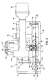
- a circular saw (30) includes a housing (32), a fixed upper guard (34), a movable lower guard (36) and a shoe (38).
- the shoe (38) is substantially flat with a slightly upturned forward end (40).
- a forward portion (42) of the housing (32) is attached for pivotal movement to a bracket (44) which is secured fixedly to one side, or an upper surface (46), of the shoe (38).
- a motor (48) is contained within an extended enclosure (50) of the housing (32) and is coupled through a gear reduction unit (not shown) to a mount (52) for a saw blade (54) having cutting teeth (55) about the periphery thereof.
- the mount (52) is rotated to thereby rotate the blade (54) and the cutting teeth (55) to facilitate the formation of a selective cut or kerf into a workpiece (57) under the control of the operator.
- the housing (32) includes a forward hand-grip section (56), an intermediate handle section (58) and a rear section (60).
- a battery housing (62) contains batteries (not shown) which supply electrical energy for operating the motor (48).
- the battery housing (62) is assembled with the rear section (60) of the housing (32), as shown in Figs. 1, 2 and 3, the batteries are electrically connected into an electrical circuit (not shown) for supplying electrical energy to the motor (48) through selective operation of a trigger switch (not shown) by the operator of the circular saw (30).
- the circular saw (30) also could be powered in a corded electrical system, or by other systems such as, for example, pressurized air or fluid, without departing from the spirit and scope of the invention.
- an arcuate arm (64) is secured to a bracket (66), which is secured to a rear portion of the upper surface (46) of the shoe (38).
- the arm (64) is formed with a closed slot (not shown) which receives a fastening element (not shown).
- the fastening element can be selectively rotated by rotation of a control knob (68) attached thereto.
- the housing (32), with the guards (34) and (36) and the saw blade (54) can be pivoted about the forward portion (42) of the housing to a selected location within the limits established by the length of the closed slot formed in the arm (64).
- the knob (68) is rotated to tighten the fastening element to secure the housing (32), the guards (34) and (36) and the saw blade (54) in the selected location.
- the operator of the saw (30) can select the distance at which the blade (54) extends from a lower surface (69) of the shoe (38), and thereby the depth of cut into the workpiece (57) as measured from the lower surface of the shoe.
- the shoe (38) is formed with an opening (86) therethrough which facilitates the positioning of the saw blade (54) with respect to the shoe. In this position, portions of the blade (54) are located above the upper surface (46) of the shoe (38) and portions of the blade are located below the lower surface (69) of the shoe as shown in Fig. 1.
- the forward end (40) of the shoe (38) is formed with a "visualization” slot (88) which is located centrally about the plane (84) of the blade (54).
- a "sight" window (90) is formed through the shoe (38) along the plane (84) between the slot (88) and the opening (86).
- the window (90) is formed with a first section (92) of a first prescribed width about the plane (84) and a second section (94) of a second prescribed width about the plane. The second prescribed width is greater than the first prescribed width.
- the second section (94) of the window (90) is formed with a first end (96) and a second end (98) spaced from the first end, with opposite sides (97) and (99) extending therebetween, and with a side-to-side width which is greater from the first end to the second end than any side-to-side width of the first section (92).
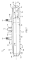
- the width of the second section (94) of the window (90) varies linearly, by diverging uniformly from the first end (96) to the second end (98) thereof, as illustrated in Fig. 3.
- the first section (92) and the second section (94) are in communication with each other.
- the sides (97) and (99) of the second section (94) of the window (90) could be formed in any configuration which includes portions spaced apart by a distance greater than the distance of any spaced portions of the sides of the first section (92).
- the configuration of either or both sides (97) and (99) of the second section (94) could be formed with, but not limited to, a curved portion, or a saw-tooth-like portion, or a stepped portion, or the second section could be formed in a square or rectangular configuration from the first end 96 to the second end (98).
- the window (90) is formed with a third section (100) which is spaced from the first section (92) and, in the preferred embodiment, is formed with a uniform width about the plane (84). While the uniform width of the third section (100) of the window (90) is the same as the prescribed width of the first section (92), the uniform width of the third section could be greater or less than the prescribed width without departing from the spirit and scope of the invention. Also, in the preferred embodiment, the second section (94) is between the first section (92) and the third section (100), with the three sections being in communication with each other.
- the second section (94) and either the first section (92) or the third section (100), or both could form openings in the shoe (38) but not be in communication with each other,
- a "depth-of-cut” stripe (102) is formed on or in the upper surface (46) of the shoe (38) on opposite sides of a forward portion (106) of the opening (86), and extends angularly from the plane (84).
- the stripe (102) is perpendicular to the plane (84) and extends to an outer edge (107) of the shoe (38).
- a portion of the stripe (102) is immediately adjacent, and is aligned with, a forwardmost location (108) at which the rotating blade (54) is situated to cut into the workpiece (57).
- the preferred embodiment of the stripe (102) is perpendicular to the plane (84), but could be at angles other than ninety degrees without departing from the spirit and scope of the invention.
- a "cut-line" stripe (104) is formed on or in the upper surface (46) of the shoe (38) within, and along, the plane (84) between the slot (88) and the window (90).
- a slight continuation of the stripe (102) is formed on or in the upper surface (46) of the shoe (38) between the window (90) and the opening (86).
- the stripes (102) and (104) are established by grooves, as illustrated in Fig. 3, formed in the upper surface (46) of the shoe (38).
- the stripes (102) and (104) could be formed in other ways without departing from the spirit and scope of the invention.
- the stripes (102) and (104) could be formed by a ridge, or by an applied marking substance having a colour which contrasts with the colour of the upper surface (46) of the shoe (38).
- the grooves, or ridges, of the stripes (102) and (104) could have a marking substance applied thereto to further enhance the visualization of the stripes.
- the upper guard (34) is formed by an inner section (112), adjacent the housing (32), and an outer section (114) which, when assembled along a seam (116), are held together by a plurality of threaded fasteners (118). While the preferred embodiment of the upper guard (34) is formed by joining the two sections (112) and (114) along the seam line (116), the upper guard (34) could be made initially as a single element, or by joining more than two sections, without departing from the spirit and scope of the invention.
- the inner section (112) of the upper guard (34) is formed generally as a shell with an internal hollow (120).
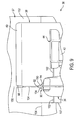
- the outer section (114) is formed generally as a shell with an internal hollow (121), as shown in Fig. 7.
- the respective hollows (120) and (121) thereof form a substantially enclosed chamber (122) (Figs. 4 and 7), in which cutting portions of the blade (54) are to be moved during the cutting of the workpiece (57).
- the enclosure of the chamber (122) is enhanced by close placement of the bottom of the upper guard (34) above the upper surface (46) of the shoe (38).
- each of the inner section (112) and the outer section (114) of the upper guard (34) is formed in a generally C-shaped configuration.
- the C-shaped structure of each section is aligned so that the upper guard assumes the C-shaped configuration.
- the upper guard (34) is formed with a first end bottom edge (124) at a first or forward end (126) thereof, and a second end bottom edge (128) at a second or rear end (130) thereof spaced from the first end. As viewed in Fig.
- the second end edge (128) is formed by spaced, straight, bottom edges (128a) and (128b) of the sections (112) and (114), and curved bottom edges (128c) of the sections (112) and (112).
- the second end edge (128) of the upper guard (34) is located above the surface (46) of the shoe (38) to form a space (129) therebetween.
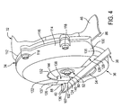
- the upper guard (34) is formed with an arcuate inner edge portion (132) which is contiguous with and extends between the first end edge (124) and the second end edge (128) to define a generally C-shaped opening (134).
- the upper guard (34) is assembled with the housing (32), with the C-shaped opening (134) facing downward toward the upper surface (46) of the shoe (38).
- the first end edge (124) of the upper guard (34) is in juxtaposition with the upper surface (46) of the shoe (38) with a slight space (39) therebetween, and is sufficiently close to the shoe to essentially preclude the discharge of chips through the space.
- the upper guard (34) is formed with a wing wall (138) along the inner edge portion (132) with the wing wall being located angularly adjacent a side wall (136) of the upper guard.
- the wing wall (138) extends toward, but does not enter, the plane (84) in which the blade (54) is located when assembled with the saw (30).
- the wing wall (138) is formed with a bottom edge (140) (Fig. 7), which, in the preferred embodiment, is flush with the first end edge (124) of the upper guard (34). The presence of the wing wall (138) further deters the discharge of chips from the forward cutting area of the saw (30).
- the chamber (142) is located in close proximity with the shoe (38) such that the chamber and the adjacent portion of the shoe provide an enclosure.
- the developed chips are essentially precluded from being discharged outside the portion of the upper guard (34) which includes the chamber (142), except for a minimal number of chips which may be discharged downward through the forward portion (106) of the shoe opening (86) and in a direction away from the operator. In any event, chips are not discharged through the space (39) between the first end edge (124) and the bottom edge (140), on the one side, and the shoe (38) on the other side.
- the wing wall (138) is perpendicular to the plane 84.
- the wing wall (138) could extend at angles greater or less than ninety degrees, toward the plane (84), without departing from the spirit and scope of the invention.
- the wing wall (138) is located adjacent the side wall (136), as illustrated in Fig. 4.
- the wing wall (138) could be located along any section of the inner edge portion (132) between the first end edge (124) and the second end edge 128, or could be longer than shown, without departing from the spirit and scope of the invention.
- an outboard surface (123) of the inner section (112) of the upper guard (34) is formed with a plurality of bosses (125) having threaded bores.
- the upper guard (34) is attached to the housing (32) by use of a corresponding plurality of screws (127) which are inserted through the extended enclosure (50) (Fig. 2) of the housing.
- the upper guard (34) is formed with the exterior side wall (136) on the outer section (114) adjacent the forward end (126) thereof.
- the side wall (136) is contiguous with and extends from the first end edge (124) for a prescribed distance to a crease line (137).
- the side wall (136) is tapered outward from the first end edge (124) to the crease line (1370 and provides enhanced viewing by the operator from above the saw (30) to a location below the side wall which includes the sight window (90) and the stripes (102) and (104).
- the outer surface of the wing wall (138) is similarly tapered outward from the bottom edge (140) thereof to a top edge (144) (Fig. 4) thereof.
- the tapered configuration of the side wall (136) and the wing wall (138) place the bottom edge (140) and the adjacent portion of the first end edge (124) closer to the plane (84) to further constrict the chamber (142) for controlled management of the chips resulting from a cutting operation.
- the hollowed opening of the upper guard is of sufficient radial extension to allow the lower guard to be swung into a space between the periphery of the cutting blade and the radially extended portion of the opening when the lower guard engages the workpiece during a cutting operation.
- a trailing peripheral portion (148) of the upper guard (34) which is located generally to the right of a vertical centreline (146), flares considerably radially outward from the bolt (80) as the trailing portion extends generally from the centreline to the rear end (130) of the upper guard.
- the upper guard (34) is formed with a first, or radially inner, path for receipt of the lower guard (36) as described above, and a second, or radially outer, path, which is radially outboard of the first path, to provide an unobstructed path for the chips passing through the chamber (142) (Fig. 7) from the cutting area to the rear end (130) of the upper guard.
- the opening (86) of the shoe (38) is formed with a large rear extended portion (135) (Fig. 3), which is adjacent and below the rear end (130) of the upper guard (34), and above the space (129).
- the location of the rear portion (135) of the shoe opening (86) facilitates the discharge of the chips from the circular saw (30), in a downward direction through the space (129), through the rear portion (135) of the shoe opening and away from the operator.
- the circular saw (30) manages the dispersement of the chips resulting from the cutting of the workpiece (57), and facilitates the discharging of the chips in a downward direction, away from the operator, either through the forward portion (106) or the rear portion (135) of the shoe opening (86).
- the operator of the circular saw (30) prepares the workpiece (57) by placing a "kerf' line (150) on a surface (152) thereof which represents the location of the cut or kerf to be formed in the workpiece.
- the operator places a "depth” line (154) on the surface (152) of the workpiece (57) which intersects the line (150) at a point representative of the depth of the kerf to be formed in the workpiece.
- the operator places the forward end of the lower surface (69) of the shoe (38) onto the surface (152) of the workpiece (57) and aligns the kerf line (150), as viewed through the slot (88), with the "cut line” stripe (104). Since the blade (54) and the stripe (104) are in the plane (84), the blade is now aligned with the kerf line (150) of the workpiece.
- the operator closes the trigger switch which facilitates the application of operating energy to the motor (48) whereby the blade (54) is rotatably driven.
- the operator moves the circular saw (30) forward toward the workpiece (57) and visually maintains the kerf line (150) in alignment with the stripe (104).
- the shoe (38) is moved over the surface (152) of the workpiece (57) and a leading portion of the kerf line (150) eventually appears within the sight window (90) prior to cutting of the workpiece.
- Spaced portions of the kerf line (150) can now be aligned with the stripe (104) by observing, at a trailing end of the stripe, a trailing portion of the kerf line through the slot (88) and on the exposed portion of the workpiece surface (152), and, at a leading end of the stripe, a leading portion of the kerf line which is visible through the sight window (90). In this manner, spaced leading and trailing portions of the kerf line (150) are readily maintained in alignment with the stripe (104) for accurate formation of the kerf.
- the teeth (55) of the blade (54) begin to form the kerf in the workpiece (57) while spaced portions of the kerf line (150), comparable to the leading and trailing portions noted above, continue to be observed at opposite ends of the stripe (104) for continued accurate formation of the kerf. Also, as the shoe (38) is moved rearward over the surface (152) of the workpiece (57), the depth line (154) on the surface (152) appears in the sight window (90) to alert the operator that the desired depth of cut is being approached.
- the circular saw (30) continues to be moved forward, the spaced leading and trailing portions of the kerf line (150) continue to be observed at opposite ends of the stripe (104) for continued accurate formation of the kerf.
- the operator continues to move the circular saw (30) forward until the operator observes that the depth line (154) on the workpiece surface (152) is aligned with the stripe (102) which indicates that the desired depth of cut has been attained.
- the operator withdraws the circular saw (30) from the workpiece (57) while releasing the trigger to remove operating energy from the motor (48).
Landscapes
- Engineering & Computer Science (AREA)
- Mechanical Engineering (AREA)
- Physics & Mathematics (AREA)
- Optics & Photonics (AREA)
- Sawing (AREA)
- Finish Polishing, Edge Sharpening, And Grinding By Specific Grinding Devices (AREA)
- Polishing Bodies And Polishing Tools (AREA)
- Stringed Musical Instruments (AREA)
Priority Applications (1)
| Application Number | Priority Date | Filing Date | Title |
|---|---|---|---|
| EP07108523A EP1914051B1 (de) | 1998-07-21 | 1999-07-21 | Kreissäge |
Applications Claiming Priority (5)
| Application Number | Priority Date | Filing Date | Title |
|---|---|---|---|
| US93505 | 1993-07-16 | ||
| US9350598P | 1998-07-21 | 1998-07-21 | |
| US09/352,016 US6308424B1 (en) | 1998-07-21 | 1999-07-12 | Circular saw |
| US352016 | 1999-07-12 | ||
| 2001-02-02 |
Related Child Applications (1)
| Application Number | Title | Priority Date | Filing Date |
|---|---|---|---|
| EP07108523A Division EP1914051B1 (de) | 1998-07-21 | 1999-07-21 | Kreissäge |
Publications (3)
| Publication Number | Publication Date |
|---|---|
| EP0974415A2 true EP0974415A2 (de) | 2000-01-26 |
| EP0974415A3 EP0974415A3 (de) | 2003-11-19 |
| EP0974415B1 EP0974415B1 (de) | 2008-11-19 |
Family
ID=26787614
Family Applications (2)
| Application Number | Title | Priority Date | Filing Date |
|---|---|---|---|
| EP07108523A Expired - Lifetime EP1914051B1 (de) | 1998-07-21 | 1999-07-21 | Kreissäge |
| EP99305777A Expired - Lifetime EP0974415B1 (de) | 1998-07-21 | 1999-07-21 | Kreissäge mit einer Sägeblattausrichtvorrichtung und Späneabfuhr |
Family Applications Before (1)
| Application Number | Title | Priority Date | Filing Date |
|---|---|---|---|
| EP07108523A Expired - Lifetime EP1914051B1 (de) | 1998-07-21 | 1999-07-21 | Kreissäge |
Country Status (4)
| Country | Link |
|---|---|
| US (2) | US6308424B1 (de) |
| EP (2) | EP1914051B1 (de) |
| AT (2) | ATE487572T1 (de) |
| DE (2) | DE69942940D1 (de) |
Cited By (2)
| Publication number | Priority date | Publication date | Assignee | Title |
|---|---|---|---|---|
| EP2886233A1 (de) * | 2013-12-19 | 2015-06-24 | Panasonic Intellectual Property Management Co., Ltd. | Angetriebene Kreissäge |
| WO2023043523A1 (en) * | 2021-09-14 | 2023-03-23 | Troy Hilsgen | Saw for cutting hard material |
Families Citing this family (28)
| Publication number | Priority date | Publication date | Assignee | Title |
|---|---|---|---|---|
| US6996909B1 (en) * | 1998-08-13 | 2006-02-14 | Black & Decker Inc. | Battery powered circular saw |
| JP4119601B2 (ja) * | 2000-07-07 | 2008-07-16 | 日立工機株式会社 | 携帯用丸鋸 |
| US6536120B1 (en) * | 2000-10-27 | 2003-03-25 | Steven J. Langis | Powered circular saw for left or right handed operation |
| US6543143B2 (en) * | 2001-04-06 | 2003-04-08 | Black & Decker Inc. | Metal cutting circular saw with integral sight window |
| JP3748073B2 (ja) * | 2002-10-22 | 2006-02-22 | 日立工機株式会社 | 電動切断機 |
| US7103979B2 (en) * | 2001-04-20 | 2006-09-12 | Hitachi Koki Co., Ltd. | Portable electric cutting device with blower mechanism |
| DE10141454A1 (de) * | 2001-08-23 | 2003-03-13 | Hilti Ag | Batteriebetriebene Kreissäge |
| USD470376S1 (en) | 2001-12-05 | 2003-02-18 | One World Technologies Limited | Cordless circular saw |
| USD466385S1 (en) | 2002-01-28 | 2002-12-03 | One World Technologies, Limited | Cordless circular saw |
| US7581323B2 (en) | 2002-09-17 | 2009-09-01 | Credo Technology Corporation | Cordless circular saw |
| USD489591S1 (en) | 2002-10-01 | 2004-05-11 | Milwaukee Electric Tool Corporation | Circular saw |
| USD514411S1 (en) | 2003-08-12 | 2006-02-07 | One World Technologies, Limited | Circular saw |
| USD507949S1 (en) | 2004-05-28 | 2005-08-02 | One World Technologies Limited | Circular saw |
| JP4466427B2 (ja) * | 2005-03-28 | 2010-05-26 | 日立工機株式会社 | 携帯用切断工具 |
| US7596872B2 (en) * | 2006-07-27 | 2009-10-06 | Robert Bosch Gmbh | Cutting attachment with a removable cover for rotary hand tools |
| US7310879B1 (en) | 2006-07-27 | 2007-12-25 | Robert Bosch Gmbh | Cutting attachment having an adjustable foot for rotary hand tools |
| DE102006048315A1 (de) * | 2006-10-12 | 2008-04-17 | Robert Bosch Gmbh | Handwerkzeugmaschine, insbesondere elektrische Schere |
| JP5396643B2 (ja) * | 2009-03-05 | 2014-01-22 | マックス株式会社 | 携帯用切断機 |
| WO2011133864A2 (en) | 2010-04-22 | 2011-10-27 | Milwaukee Electric Tool Corporation | Saw blade |
| US10189099B2 (en) | 2010-04-22 | 2019-01-29 | Milwaukee Electric Tool Corporation | Saw Blade |
| JP5730602B2 (ja) * | 2011-02-09 | 2015-06-10 | 株式会社マキタ | 切断工具 |
| USD841417S1 (en) | 2011-04-22 | 2019-02-26 | Milwaukee Electric Tool Corporation | Saw blade |
| US20160121513A1 (en) * | 2014-10-30 | 2016-05-05 | Robert Bosch Tool Corporation | Lower Blade Guard for a Circular Saw |
| US10654188B2 (en) * | 2014-12-31 | 2020-05-19 | Robert Bosch Tool Corporation | Guide foot for an oscillating cutting tool |
| US11413693B2 (en) | 2017-05-16 | 2022-08-16 | Milwaukee Electric Tool Corporation | Saw blade |
| US20190111634A1 (en) * | 2017-10-13 | 2019-04-18 | Tti (Macao Commercial Offshore) Limited | Battery powered carpet seamer |
| US10875109B1 (en) | 2018-04-30 | 2020-12-29 | Kreg Enterprises, Inc. | Adaptive cutting system |
| USD945234S1 (en) * | 2018-07-26 | 2022-03-08 | Paul Mueller Company | Guard for use with a power tool |
Citations (2)
| Publication number | Priority date | Publication date | Assignee | Title |
|---|---|---|---|---|
| US4555849A (en) | 1982-06-21 | 1985-12-03 | Matsushita Electric Works, Ltd. | Battery powered portable saw |
| US4856394A (en) | 1988-04-14 | 1989-08-15 | Porter-Cable Corporation | Portable circular saw |
Family Cites Families (14)
| Publication number | Priority date | Publication date | Assignee | Title |
|---|---|---|---|---|
| US1854510A (en) * | 1929-11-06 | 1932-04-19 | Walt Products Corp De | Portable power driven saw |
| US1830579A (en) | 1930-01-30 | 1931-11-03 | Wappat Inc | Electric handsaw |
| US2795248A (en) | 1955-01-11 | 1957-06-11 | Dormeyer Corp | Eyeguard for power saw |
| DE1040771B (de) | 1956-04-11 | 1958-10-09 | Gotthold Haffner Fa | Motorhandkreissaege mit einer unter die Festhaube ruecklaufenden Pendelschutzhaube |
| US2839098A (en) * | 1956-12-28 | 1958-06-17 | Millers Falls Co | Cut-line indicator for portable circular saw |
| US2854043A (en) * | 1957-05-13 | 1958-09-30 | Raymond Ray | Insert saw attachment to eliminate splintering |
| DE3104340C2 (de) * | 1980-03-06 | 1986-06-05 | AEG Power Tool Corp. (APTC), Norwich, Conn. | Tragbare Kreissäge |
| US4450627A (en) | 1981-07-06 | 1984-05-29 | Shindaiwa Kogyo Co., Ltd. | Device for determining a correct sawing position for a portable rotary sawing machine |
| US4675999A (en) | 1984-11-16 | 1987-06-30 | Hitachi Koki Company, Ltd. | Portable power tool equipped with dust collector |
| US5023999A (en) * | 1990-08-09 | 1991-06-18 | Ryobi Motor Products Corp. | Unitized tool construction |
| US5537748A (en) * | 1991-07-09 | 1996-07-23 | Ryobi Limited | Cover structure for electric circular saw |
| US5327649A (en) * | 1993-02-11 | 1994-07-12 | Skinner Christopher L | Circular saw with dust collector |
| JP3214295B2 (ja) * | 1995-05-12 | 2001-10-02 | 日立工機株式会社 | 携帯用集じん丸のこ |
| US5822864A (en) * | 1996-05-31 | 1998-10-20 | Black & Decker, Inc. | Viewing window for circular saw guard |
-
1999
- 1999-07-12 US US09/352,016 patent/US6308424B1/en not_active Expired - Lifetime
- 1999-07-21 DE DE69942940T patent/DE69942940D1/de not_active Expired - Lifetime
- 1999-07-21 DE DE69939923T patent/DE69939923D1/de not_active Expired - Lifetime
- 1999-07-21 EP EP07108523A patent/EP1914051B1/de not_active Expired - Lifetime
- 1999-07-21 AT AT07108523T patent/ATE487572T1/de not_active IP Right Cessation
- 1999-07-21 AT AT99305777T patent/ATE414582T1/de not_active IP Right Cessation
- 1999-07-21 EP EP99305777A patent/EP0974415B1/de not_active Expired - Lifetime
-
2001
- 2001-06-07 US US09/875,205 patent/US6625891B2/en not_active Expired - Fee Related
Patent Citations (2)
| Publication number | Priority date | Publication date | Assignee | Title |
|---|---|---|---|---|
| US4555849A (en) | 1982-06-21 | 1985-12-03 | Matsushita Electric Works, Ltd. | Battery powered portable saw |
| US4856394A (en) | 1988-04-14 | 1989-08-15 | Porter-Cable Corporation | Portable circular saw |
Cited By (3)
| Publication number | Priority date | Publication date | Assignee | Title |
|---|---|---|---|---|
| EP2886233A1 (de) * | 2013-12-19 | 2015-06-24 | Panasonic Intellectual Property Management Co., Ltd. | Angetriebene Kreissäge |
| JP2015116645A (ja) * | 2013-12-19 | 2015-06-25 | パナソニックIpマネジメント株式会社 | 電動丸鋸 |
| WO2023043523A1 (en) * | 2021-09-14 | 2023-03-23 | Troy Hilsgen | Saw for cutting hard material |
Also Published As
| Publication number | Publication date |
|---|---|
| DE69939923D1 (de) | 2009-01-02 |
| US6625891B2 (en) | 2003-09-30 |
| EP1914051B1 (de) | 2010-11-10 |
| EP0974415A3 (de) | 2003-11-19 |
| EP1914051A3 (de) | 2008-07-02 |
| EP1914051A2 (de) | 2008-04-23 |
| ATE487572T1 (de) | 2010-11-15 |
| EP0974415B1 (de) | 2008-11-19 |
| US6308424B1 (en) | 2001-10-30 |
| ATE414582T1 (de) | 2008-12-15 |
| US20020121024A1 (en) | 2002-09-05 |
| DE69942940D1 (de) | 2010-12-23 |
Similar Documents
| Publication | Publication Date | Title |
|---|---|---|
| EP1914051B1 (de) | Kreissäge | |
| JP3761771B2 (ja) | ノコギリ用のダスト収集ポート | |
| US5675899A (en) | Rotary saw with laser beam alignment | |
| JP4733952B2 (ja) | 切断機 | |
| US4730397A (en) | Jig saw with two-piece shoe | |
| US7219434B2 (en) | Metal cutting circular saw with integral sight window | |
| US20060207683A1 (en) | Power tool | |
| US20050284543A1 (en) | Pre-directing insert for a bi-directional exhausting handheld planer | |
| US6116349A (en) | Vegetation cutter with guide | |
| US5407012A (en) | Portable handheld edge cutter | |
| CA1043083A (en) | Cable stripping tool | |
| EP1708858B1 (de) | Angetriebene kreissäge mit gebläsesystem und gehrungsquadrant | |
| US4959907A (en) | Circular saw accessory | |
| JPH0731932Y2 (ja) | 携帯用防塵丸鋸機 | |
| JP4195474B2 (ja) | 切断機 | |
| JP2912564B2 (ja) | 携帯用回転工具 | |
| CN222155737U (zh) | 分切刀 | |
| JPH065053Y2 (ja) | 手持式ロータリカッタ | |
| JPH077121Y2 (ja) | 卓上切断機の切粉排出装置 | |
| JPH08174331A (ja) | 全ネジ切断機 | |
| KR900005165Y1 (ko) | 목초 예취기의 회전커터 안전장치 | |
| JP3580742B2 (ja) | 切粉遮蔽機能付き携帯用電気マルノコ | |
| JP4782819B2 (ja) | 切断機 | |
| JP3019686U (ja) | 草刈機の刈刃 | |
| JP2006289987A (ja) | 切断機 |
Legal Events
| Date | Code | Title | Description |
|---|---|---|---|
| PUAI | Public reference made under article 153(3) epc to a published international application that has entered the european phase |
Free format text: ORIGINAL CODE: 0009012 |
|
| AK | Designated contracting states |
Kind code of ref document: A2 Designated state(s): AT BE CH CY DE DK ES FI FR GB GR IE IT LI LU MC NL PT SE |
|
| AX | Request for extension of the european patent |
Free format text: AL;LT;LV;MK;RO;SI |
|
| PUAL | Search report despatched |
Free format text: ORIGINAL CODE: 0009013 |
|
| AK | Designated contracting states |
Kind code of ref document: A3 Designated state(s): AT BE CH CY DE DK ES FI FR GB GR IE IT LI LU MC NL PT SE |
|
| AX | Request for extension of the european patent |
Extension state: AL LT LV MK RO SI |
|
| 17P | Request for examination filed |
Effective date: 20040224 |
|
| AKX | Designation fees paid |
Designated state(s): AT BE CH CY DE DK ES FI FR GB GR IE IT LI LU MC NL PT SE |
|
| GRAP | Despatch of communication of intention to grant a patent |
Free format text: ORIGINAL CODE: EPIDOSNIGR1 |
|
| GRAS | Grant fee paid |
Free format text: ORIGINAL CODE: EPIDOSNIGR3 |
|
| GRAA | (expected) grant |
Free format text: ORIGINAL CODE: 0009210 |
|
| AK | Designated contracting states |
Kind code of ref document: B1 Designated state(s): AT BE CH CY DE DK ES FI FR GB GR IE IT LI LU MC NL PT SE |
|
| REG | Reference to a national code |
Ref country code: GB Ref legal event code: FG4D |
|
| REG | Reference to a national code |
Ref country code: CH Ref legal event code: EP |
|
| REG | Reference to a national code |
Ref country code: IE Ref legal event code: FG4D |
|
| REF | Corresponds to: |
Ref document number: 69939923 Country of ref document: DE Date of ref document: 20090102 Kind code of ref document: P |
|
| REG | Reference to a national code |
Ref country code: SE Ref legal event code: TRGR |
|
| PG25 | Lapsed in a contracting state [announced via postgrant information from national office to epo] |
Ref country code: ES Free format text: LAPSE BECAUSE OF FAILURE TO SUBMIT A TRANSLATION OF THE DESCRIPTION OR TO PAY THE FEE WITHIN THE PRESCRIBED TIME-LIMIT Effective date: 20090301 Ref country code: AT Free format text: LAPSE BECAUSE OF FAILURE TO SUBMIT A TRANSLATION OF THE DESCRIPTION OR TO PAY THE FEE WITHIN THE PRESCRIBED TIME-LIMIT Effective date: 20081119 |
|
| NLV1 | Nl: lapsed or annulled due to failure to fulfill the requirements of art. 29p and 29m of the patents act | ||
| PG25 | Lapsed in a contracting state [announced via postgrant information from national office to epo] |
Ref country code: NL Free format text: LAPSE BECAUSE OF FAILURE TO SUBMIT A TRANSLATION OF THE DESCRIPTION OR TO PAY THE FEE WITHIN THE PRESCRIBED TIME-LIMIT Effective date: 20081119 Ref country code: FI Free format text: LAPSE BECAUSE OF FAILURE TO SUBMIT A TRANSLATION OF THE DESCRIPTION OR TO PAY THE FEE WITHIN THE PRESCRIBED TIME-LIMIT Effective date: 20081119 |
|
| PG25 | Lapsed in a contracting state [announced via postgrant information from national office to epo] |
Ref country code: DK Free format text: LAPSE BECAUSE OF FAILURE TO SUBMIT A TRANSLATION OF THE DESCRIPTION OR TO PAY THE FEE WITHIN THE PRESCRIBED TIME-LIMIT Effective date: 20081119 Ref country code: BE Free format text: LAPSE BECAUSE OF FAILURE TO SUBMIT A TRANSLATION OF THE DESCRIPTION OR TO PAY THE FEE WITHIN THE PRESCRIBED TIME-LIMIT Effective date: 20081119 |
|
| PG25 | Lapsed in a contracting state [announced via postgrant information from national office to epo] |
Ref country code: PT Free format text: LAPSE BECAUSE OF FAILURE TO SUBMIT A TRANSLATION OF THE DESCRIPTION OR TO PAY THE FEE WITHIN THE PRESCRIBED TIME-LIMIT Effective date: 20090420 |
|
| PLBE | No opposition filed within time limit |
Free format text: ORIGINAL CODE: 0009261 |
|
| STAA | Information on the status of an ep patent application or granted ep patent |
Free format text: STATUS: NO OPPOSITION FILED WITHIN TIME LIMIT |
|
| 26N | No opposition filed |
Effective date: 20090820 |
|
| PG25 | Lapsed in a contracting state [announced via postgrant information from national office to epo] |
Ref country code: MC Free format text: LAPSE BECAUSE OF NON-PAYMENT OF DUE FEES Effective date: 20090731 |
|
| REG | Reference to a national code |
Ref country code: CH Ref legal event code: PL |
|
| REG | Reference to a national code |
Ref country code: FR Ref legal event code: ST Effective date: 20100331 |
|
| REG | Reference to a national code |
Ref country code: IE Ref legal event code: MM4A |
|
| PG25 | Lapsed in a contracting state [announced via postgrant information from national office to epo] |
Ref country code: LI Free format text: LAPSE BECAUSE OF NON-PAYMENT OF DUE FEES Effective date: 20090731 Ref country code: FR Free format text: LAPSE BECAUSE OF NON-PAYMENT OF DUE FEES Effective date: 20090731 Ref country code: CH Free format text: LAPSE BECAUSE OF NON-PAYMENT OF DUE FEES Effective date: 20090731 |
|
| PG25 | Lapsed in a contracting state [announced via postgrant information from national office to epo] |
Ref country code: IE Free format text: LAPSE BECAUSE OF NON-PAYMENT OF DUE FEES Effective date: 20090721 |
|
| PG25 | Lapsed in a contracting state [announced via postgrant information from national office to epo] |
Ref country code: GR Free format text: LAPSE BECAUSE OF FAILURE TO SUBMIT A TRANSLATION OF THE DESCRIPTION OR TO PAY THE FEE WITHIN THE PRESCRIBED TIME-LIMIT Effective date: 20090220 |
|
| PG25 | Lapsed in a contracting state [announced via postgrant information from national office to epo] |
Ref country code: LU Free format text: LAPSE BECAUSE OF NON-PAYMENT OF DUE FEES Effective date: 20090721 |
|
| PG25 | Lapsed in a contracting state [announced via postgrant information from national office to epo] |
Ref country code: CY Free format text: LAPSE BECAUSE OF FAILURE TO SUBMIT A TRANSLATION OF THE DESCRIPTION OR TO PAY THE FEE WITHIN THE PRESCRIBED TIME-LIMIT Effective date: 20081119 |
|
| PGFP | Annual fee paid to national office [announced via postgrant information from national office to epo] |
Ref country code: SE Payment date: 20120727 Year of fee payment: 14 Ref country code: GB Payment date: 20120725 Year of fee payment: 14 |
|
| PGFP | Annual fee paid to national office [announced via postgrant information from national office to epo] |
Ref country code: IT Payment date: 20120724 Year of fee payment: 14 |
|
| PGFP | Annual fee paid to national office [announced via postgrant information from national office to epo] |
Ref country code: DE Payment date: 20130729 Year of fee payment: 15 |
|
| REG | Reference to a national code |
Ref country code: SE Ref legal event code: EUG |
|
| GBPC | Gb: european patent ceased through non-payment of renewal fee |
Effective date: 20130721 |
|
| PG25 | Lapsed in a contracting state [announced via postgrant information from national office to epo] |
Ref country code: GB Free format text: LAPSE BECAUSE OF NON-PAYMENT OF DUE FEES Effective date: 20130721 Ref country code: SE Free format text: LAPSE BECAUSE OF NON-PAYMENT OF DUE FEES Effective date: 20130722 |
|
| PG25 | Lapsed in a contracting state [announced via postgrant information from national office to epo] |
Ref country code: IT Free format text: LAPSE BECAUSE OF NON-PAYMENT OF DUE FEES Effective date: 20130721 |
|
| REG | Reference to a national code |
Ref country code: DE Ref legal event code: R119 Ref document number: 69939923 Country of ref document: DE |
|
| PG25 | Lapsed in a contracting state [announced via postgrant information from national office to epo] |
Ref country code: DE Free format text: LAPSE BECAUSE OF NON-PAYMENT OF DUE FEES Effective date: 20150203 |
|
| REG | Reference to a national code |
Ref country code: DE Ref legal event code: R119 Ref document number: 69939923 Country of ref document: DE Effective date: 20150203 |