EP0974430A2 - Outil à main entraíné par un moteur électrique, notamment une scie sauteuse - Google Patents
Outil à main entraíné par un moteur électrique, notamment une scie sauteuse Download PDFInfo
- Publication number
- EP0974430A2 EP0974430A2 EP99305711A EP99305711A EP0974430A2 EP 0974430 A2 EP0974430 A2 EP 0974430A2 EP 99305711 A EP99305711 A EP 99305711A EP 99305711 A EP99305711 A EP 99305711A EP 0974430 A2 EP0974430 A2 EP 0974430A2
- Authority
- EP
- European Patent Office
- Prior art keywords
- rotor shaft
- countershaft
- projections
- electric tool
- shaft
- Prior art date
- Legal status (The legal status is an assumption and is not a legal conclusion. Google has not performed a legal analysis and makes no representation as to the accuracy of the status listed.)
- Granted
Links
Images


Classifications
-
- B—PERFORMING OPERATIONS; TRANSPORTING
- B23—MACHINE TOOLS; METAL-WORKING NOT OTHERWISE PROVIDED FOR
- B23D—PLANING; SLOTTING; SHEARING; BROACHING; SAWING; FILING; SCRAPING; LIKE OPERATIONS FOR WORKING METAL BY REMOVING MATERIAL, NOT OTHERWISE PROVIDED FOR
- B23D51/00—Sawing machines or sawing devices working with straight blades, characterised only by constructional features of particular parts; Carrying or attaching means for tools, covered by this subclass, which are connected to a carrier at both ends
- B23D51/16—Sawing machines or sawing devices working with straight blades, characterised only by constructional features of particular parts; Carrying or attaching means for tools, covered by this subclass, which are connected to a carrier at both ends of drives or feed mechanisms for straight tools, e.g. saw blades, or bows
Definitions
- the invention relates to a hand-operated electric tool, especially a jigsaw, having a motor unit provided in the tool housing, which motor unit contains in a motor housing the stator and the rotor, wherein the rotor shaft projecting with one end from the motor housing is mounted in two bearings fixed in the motor housing, having a gear arrangement which is arranged to be driven by the rotor shaft, which gear arrangement is coupled to the rotor shaft by way of a countershaft that forms an extension of the rotor shaft and is rotatably mounted in a bearing, and having a tool chuck which is arranged to be driven by means of the gear arrangement.
- Electric tools especially jigsaws, in which a pre-assembled motor unit is provided for the drive, are well known.
- the use of the pre-assembled motor unit which is manufactured in large piece numbers and therefore economically, has the advantage that the very compact construction of the motor unit enables it to be mounted by fixing the motor housing in the housing of the electric tool, without the rotor and stator having to mounted in separate steps and without any need for the bearings of the rotor shaft to be set in specially constructed locating regions of the housing of the electric tool.
- a countershaft has to be provided, which acts as an extension of the rotor shaft and has a toothed arrangement, preferably a pinion, which meshes with the input gearwheel of the gear arrangement.
- This countershaft has to be rotatably mounted in an additional bearing, and it is normally rigidly connected to the rotor shaft.
- the bearings of such a three-point bearing cannot be coaxially aligned with absolute accuracy, however, so that in operation the rotating unit comprising rotor shaft and countershaft is subject to bending stresses.
- the invention is based on the problem of eliminating the risk of fracture arising in the known construction.
- an electric tool of the kind mentioned in the introduction is constructed in accordance with the invention so that rotor shaft and countershaft engage one another axially with radial play and are coupled non-rotatably to one another by radial projections on the one shaft and complementary recesses receiving the projections on the other shaft, and so that, in the region of the overlapping portions of rotor shaft and countershaft, on one of the shafts there is provided an annular portion extending at least over a part of the circumference, which annular portion is substantially in line contact with the adjacent circumferential surface of the other shaft.
- the rotor shaft mounted in the two bearings provided in the motor housing and the countershaft mounted in an additional bearing are uncoupled from one another as a consequence of the engagement with radial play, so that the inevitable misalignment of the bearings does not lead to the disadvantageous bending stresses of a three-point bearing, on the contrary, corresponding to an inevitable misalignment of their bearing arrangements, rotor shaft and countershaft are likewise not aligned exactly coaxially with respect to one another.
- Locking of the rotor shaft and countershaft to prevent rotation, and hence the transfer of the rotary movement from the rotor shaft to the countershaft and from there to the gear, is achieved by the interlocking engagement of rotor shaft and countershaft by virtue of the radial projections and the recesses receiving them.
- two projections lying diagonally opposite one another are present, and the annular portion extends on both sides between the projections, that is, forms two diagonally opposite component portions.
- the rotor shaft can extend with a bushing affixed thereto into a coaxial opening in the countershaft, and the projections and the annular portion can then be formed on the bushing.
- a further source of noise in the coupling of rotor shaft and countershaft provided is located in the region between the lateral surfaces of the projections and the lateral surfaces faces or axially running walls for the recesses receiving the projections.
- a lateral wall of a projection comes into torque-transferring engagement with a lateral wall of the associated recess, this engagement varying in operation in dependence on the loading occurring.
- the recesses can have resiliently deformable supporting portions abutting the projections on both sides.
- a fan wheel of plastics material in the hub of which the recesses extend, sits on the countershaft, and the supporting portions are formed integral with the fan wheel and from the plastics material thereof.
- the construction of the jigsaw corresponds substantially to the conventional construction of an electric tool of that kind, so that details that are not essential to the invention are not explained more specifically.
- the customary gear for such jigsaws is not, incidentally, shown in the Figures, and the part of this gear at the front in the saw housing is indicated in Figure 3 merely as a hatched area.
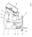
- the jigsaw illustrated has, as already mentioned, a jigsaw housing 1, the upper middle portion of which forms a grip region 2, beneath which there is provided a grip opening 3 into which the operating element 4 for the ON/OFF switch extends in the customary manner.
- a battery 15 is releasably secured to the rear end of the jigsaw housing 1.
- At the front upper part of the jigsaw housing 1 there is a change lever 11; this change lever is connected by way of a connection 48 to the combination of ram 10, moving back and forth in operation, and saw blade clamp 9 secured thereto, and is used in known manner to bring the saw blade clamp 9 into an opened state and a clamped state, in which a jigsaw blade 12 is retained in the clamp.
- the jigsaw blade 12 extends through the window, open towards the front, of a customary shoe 6, which is secured to the lower part of the jigsaw housing 1 by means of an arched portion 7.
- a customary shoe 6 which is secured to the lower part of the jigsaw housing 1 by means of an arched portion 7.
- the clamped fastening of the shoe 6 can be released and by turning the shoe 6 the bearing surface thereof can be brought into an inclined position with respect to the jigsaw blade 12 and the shoe 6 can be clamped in that position again in order thus, as is common in jigsaws, to obtain an inclined cutting edge setting.
- the jigsaw illustrated contains a motor unit, which contains in a motor housing 20 the stator, not illustrated, and the rotor, the rotor shaft 21 of which projects at one end from the motor housing 20.
- the motor unit there are two bearings, not illustrated, for rotatable mounting of the rotor shaft 21.
- Such motor units are commercially available and are increasingly being used in electric tools because of their favourable price.
- the motor unit is secured by means of screws, not illustrated in detail, to a location plate 14 in the form of a housing part which is screwed to a housing section 13.
- the countershaft 30 is aligned coaxial with the rotor shaft 21 and at its end remote from the motor unit forms a pinion 34, which, in a manner not illustrated, meshes with an input gearwheel of the jigsaw gear.
- the countershaft 30 has an enlarged cross-section 32 and forms there a recess or opening 33 open to the motor unit.
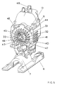
- the outside of the countershaft 30 is in the form of a splined shaft ( Figures 4 and 5), and the hub 41 of a plastics material fan wheel 40 is placed thereon.
- This fan wheel extends in a space formed between retaining plate 14 and the rear wall of housing part 13 facing the motor unit.
- the region 32 of the countershaft 30 has diagonally opposite indentations open towards the motor unit which continue radially outwards as openings 42, 43 ( Figure 5) of the hub 41 of the fan wheel 40.
- a bushing 22 is secured non-rotatably on the free end of the rotor shaft 21, and on the bushing there are formed projections 23, 24 lying diagonally opposite one another which in the mounted state engage in the openings 42, 43 in the fan wheel.
- the supporting portions 44, 45, and 46. 47 then abut the sides of the projections 23, 24.
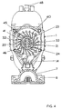
- Component regions 25, 26 of an annular portion ( Figure 3) formed integral with the bushing 22 extend between the projections 23, 24 on both sides against the outer surface of the bushing 22, the annular portion lying in a plane perpendicular to the longitudinal axis of the rotor shaft 21 and the longitudinal axis of the countershaft 30 arranged coaxial therewith.
- the annular portion In the mounted state, the annular portion is in line contact with the inner circumferential surface of the opening 33 of the countershaft 30, whilst otherwise there is radial clearance between the outer surface of the bushing 22 and the inner circumferential surface of the opening 33.
- the engagement of the projections 23 and 24 of the bushing mounted non-rotatably on the rotor shaft 21 with the openings 42, 43 in the fan wheel 40 mounted non-rotatably on the countershaft 30 produces a coupling for transfer of the rotary movement of the rotor shaft 21 to the countershaft 30.
- rotations of the countershaft 30 and rotor shaft 21 relative to one another for instance as a consequence of sudden loading on the countershaft 30 resulting from impact stress occurring at the jigsaw blade 12, are damped by the resiliently deformable supporting portions 44, 45 and 46, 47 abutting the projections 23, 24 laterally, so that generation of noise that is otherwise possible is considerably reduced.
- the rotor shaft 21 is rotatably mounted in two bearings in the motor housing 20, whilst the countershaft 30 is mounted in the bearings 31 located in the housing part 13.
- This three-point bearing makes it practically impossible to align rotor shaft 21 and countershaft 30 exactly coaxially with one another.
- the bushing 22 is located with radial play in the opening 33 of the countershaft 30 and because there is only line contact, via the annular portion 25, 26, between inner surface of the opening 33 and outer surface of the bushing 22, rotor shaft 21 and countershaft 30 are able to engage one another with a slight misalignment, this misalignment being accommodated by a corresponding displacement of the annular portion 25, 26 within the opening 33.
- the line contact between annular portion 25, 26 and inner surface of the opening 33 is maintained, and it has unexpectedly been shown that this engagement dramatically reduces the considerable generation of noise that would otherwise occur in this coupling region.
Landscapes
- Engineering & Computer Science (AREA)
- Mechanical Engineering (AREA)
- Sawing (AREA)
- Connection Of Motors, Electrical Generators, Mechanical Devices, And The Like (AREA)
- Portable Power Tools In General (AREA)
- Motor Or Generator Frames (AREA)
Applications Claiming Priority (2)
| Application Number | Priority Date | Filing Date | Title |
|---|---|---|---|
| DE19833794A DE19833794A1 (de) | 1998-07-21 | 1998-07-21 | Handgeführtes Elektrowerkzeug, insbesondere Stichsäge |
| DE19833794 | 1998-07-21 |
Publications (3)
| Publication Number | Publication Date |
|---|---|
| EP0974430A2 true EP0974430A2 (fr) | 2000-01-26 |
| EP0974430A3 EP0974430A3 (fr) | 2000-02-09 |
| EP0974430B1 EP0974430B1 (fr) | 2003-10-08 |
Family
ID=7875483
Family Applications (1)
| Application Number | Title | Priority Date | Filing Date |
|---|---|---|---|
| EP99305711A Expired - Lifetime EP0974430B1 (fr) | 1998-07-21 | 1999-07-20 | Outil à main entraíné par un moteur électrique, notamment une scie sauteuse |
Country Status (6)
| Country | Link |
|---|---|
| US (1) | US6241027B1 (fr) |
| EP (1) | EP0974430B1 (fr) |
| JP (1) | JP2000042829A (fr) |
| AT (1) | ATE251527T1 (fr) |
| DE (2) | DE19833794A1 (fr) |
| ES (1) | ES2204070T3 (fr) |
Cited By (1)
| Publication number | Priority date | Publication date | Assignee | Title |
|---|---|---|---|---|
| CN103862442A (zh) * | 2012-12-13 | 2014-06-18 | 苏州宝时得电动工具有限公司 | 一种具有冲击扳手功能的动力工具 |
Families Citing this family (16)
| Publication number | Priority date | Publication date | Assignee | Title |
|---|---|---|---|---|
| USD455328S1 (en) | 2001-08-31 | 2002-04-09 | S-B Power Tool Company | Articulated jigsaw |
| USD454476S1 (en) | 2001-08-31 | 2002-03-19 | S-B Power Tool Company | Articulated jigsaw |
| USD462591S1 (en) | 2001-11-05 | 2002-09-10 | Porter-Cable/Delta | Cordless jig saw |
| GB2415660A (en) * | 2004-06-29 | 2006-01-04 | Black & Decker Inc | Shoe assembly for power tool |
| USD525097S1 (en) | 2004-06-04 | 2006-07-18 | One World Technologies Limited | Jigsaw |
| USD521335S1 (en) | 2004-09-17 | 2006-05-23 | One World Technologies Ltd. | Jigsaw |
| US20070074407A1 (en) * | 2005-09-30 | 2007-04-05 | Serdynski David P | Tool and method of using same |
| GB2469785B (en) * | 2008-03-07 | 2012-12-19 | Milwaukee Electric Tool Corp | Reciprocating saw |
| US8230607B2 (en) | 2008-05-09 | 2012-07-31 | Milwaukee Electric Tool Corporation | Keyless blade clamp for a power tool |
| JP5854914B2 (ja) * | 2012-04-20 | 2016-02-09 | 株式会社マキタ | 充電式電動工具 |
| US11139722B2 (en) | 2018-03-02 | 2021-10-05 | Black & Decker Inc. | Motor having an external heat sink for a power tool |
| WO2019177753A1 (fr) | 2018-03-16 | 2019-09-19 | Milwaukee Electric Tool Corporation | Serre-lame pour outil électrique |
| USD887806S1 (en) | 2018-04-03 | 2020-06-23 | Milwaukee Electric Tool Corporation | Jigsaw |
| EP3774148B1 (fr) | 2018-04-03 | 2025-02-12 | Milwaukee Electric Tool Corporation | Scie sauteuse |
| US11877976B2 (en) | 2019-11-06 | 2024-01-23 | Threesixty Sourcing Limited | Physical therapy device with percussion, cooling, and heating |
| US20220362052A1 (en) | 2021-05-17 | 2022-11-17 | MerchSource, LLC | Temperature-Controlled Massage Node |
Family Cites Families (28)
| Publication number | Priority date | Publication date | Assignee | Title |
|---|---|---|---|---|
| DE1726395U (de) * | 1954-04-22 | 1956-07-19 | Licentia Gmbh | Einrichtung zum ausrichten der polachsen von mittelfrequenzaggregaten. |
| US2890072A (en) | 1956-07-10 | 1959-06-09 | Thor Power Tool Co | Retainer for rotary power tools |
| DE1913766C2 (de) | 1969-03-19 | 1982-08-19 | Robert Bosch Gmbh, 7000 Stuttgart | Lageranordnung für die über zwei Wälzlager in einem Gehäuse gelagerte Rotorwelle eines Elektromotors |
| DE7803299U1 (de) | 1978-02-04 | 1978-05-18 | Pfaff Haushaltmaschinen Gmbh, 7500 Karlsruhe | Kommutatormotor |
| IT7823020U1 (it) * | 1978-10-11 | 1980-04-11 | Fabbrica Italiana Magneti Marelli Spa | Dispositivo per l'accoppiamento torsionale elastico fra mozzo e ruota, in particolare per motoriduttori di limitata potenza |
| US4385898A (en) | 1981-04-09 | 1983-05-31 | The Bendix Corporation | Hydraulic control apparatus |
| SU1024367A1 (ru) | 1982-02-04 | 1983-06-23 | Дальневосточный технический институт рыбной промышленности и хозяйства | Дейдвудное устройство |
| US4518369A (en) | 1983-04-20 | 1985-05-21 | Kabushiki Kaisha Komatsu Seisakusho | Coupling arrangement for rotating shafts |
| FR2561339A1 (fr) | 1984-03-14 | 1985-09-20 | Paris & Du Rhone | Montage antivibratoire et/ou antibruit pour organe monte sur une machine tournante electrique, et application de ce montage a un ventilateur de machine tournante electrique |
| US4661009A (en) | 1986-03-12 | 1987-04-28 | Grentek, Inc. | Quick change coupling for machine tool arbors and the like |
| DE3624386A1 (de) | 1986-07-18 | 1988-01-28 | Siemens Ag | Luefter fuer eine elektrische maschine |
| DE3643066A1 (de) | 1986-12-17 | 1988-06-30 | Bosch Gmbh Robert | Drehendes elektrowerkzeug, insbesondere winkelschleifer |
| US4902162A (en) | 1988-04-19 | 1990-02-20 | Emerson Electric Co. | Shaft and rotatable machine element assembly |
| JPH0741901Y2 (ja) | 1990-06-12 | 1995-09-27 | 株式会社ナブコ | ポンプ装置 |
| US5023999A (en) * | 1990-08-09 | 1991-06-18 | Ryobi Motor Products Corp. | Unitized tool construction |
| DE4113649A1 (de) | 1991-04-26 | 1992-10-29 | Bosch Gmbh Robert | Handwerkzeugmaschine |
| JP3195068B2 (ja) | 1992-09-02 | 2001-08-06 | 株式会社マキタ | レシプロソー |
| SE502180C2 (sv) * | 1993-04-19 | 1995-09-11 | Dentatus Ab | Handapparat för fram- och återgående drivning av bearbetningsverktyg |
| US5450925A (en) * | 1994-04-05 | 1995-09-19 | S-B Power Tool Company | Lubrication system for a reciprocating power tool |
| DE9408089U1 (de) | 1994-05-17 | 1995-09-14 | Robert Bosch Gmbh, 70469 Stuttgart | Handwerkzeugmaschine |
| FR2723155B1 (fr) | 1994-07-26 | 1996-10-11 | Nacam | Dispositif d'accouplement de deux arbres |
| DE9414782U1 (de) * | 1994-08-31 | 1994-11-03 | Wang Cheng, Chiu-Yu, Chia-Yi | Elektrischer Schraubenschlüssel |
| US5873282A (en) * | 1994-09-29 | 1999-02-23 | Black & Decker Inc. | Armature shaft deflection limiter |
| US5555626A (en) * | 1995-11-27 | 1996-09-17 | S-B Power Tool Company | Reciprocating drive mechanism |
| US5765652A (en) * | 1996-07-05 | 1998-06-16 | Ryobi North America, Inc. | Universal joint for a motorized implement |
| US5727322A (en) * | 1996-12-31 | 1998-03-17 | Black & Decker Inc. | Adjustable shoe for a jig saw |
| DE19717466B4 (de) * | 1997-04-25 | 2005-09-08 | Robert Bosch Gmbh | Mehrganggetriebe für Elektrowerkzeugmaschinen |
| US6026909A (en) * | 1998-10-30 | 2000-02-22 | Techtronic Industries Co., Ltd. | Power tool |
-
1998
- 1998-07-21 DE DE19833794A patent/DE19833794A1/de not_active Withdrawn
-
1999
- 1999-07-15 JP JP11201237A patent/JP2000042829A/ja active Pending
- 1999-07-20 EP EP99305711A patent/EP0974430B1/fr not_active Expired - Lifetime
- 1999-07-20 AT AT99305711T patent/ATE251527T1/de not_active IP Right Cessation
- 1999-07-20 DE DE69911864T patent/DE69911864T2/de not_active Expired - Lifetime
- 1999-07-20 ES ES99305711T patent/ES2204070T3/es not_active Expired - Lifetime
- 1999-07-21 US US09/358,639 patent/US6241027B1/en not_active Expired - Lifetime
Cited By (2)
| Publication number | Priority date | Publication date | Assignee | Title |
|---|---|---|---|---|
| CN103862442A (zh) * | 2012-12-13 | 2014-06-18 | 苏州宝时得电动工具有限公司 | 一种具有冲击扳手功能的动力工具 |
| CN103862442B (zh) * | 2012-12-13 | 2016-08-03 | 苏州宝时得电动工具有限公司 | 一种具有冲击扳手功能的动力工具 |
Also Published As
| Publication number | Publication date |
|---|---|
| ATE251527T1 (de) | 2003-10-15 |
| EP0974430B1 (fr) | 2003-10-08 |
| DE69911864D1 (de) | 2003-11-13 |
| US6241027B1 (en) | 2001-06-05 |
| EP0974430A3 (fr) | 2000-02-09 |
| JP2000042829A (ja) | 2000-02-15 |
| DE69911864T2 (de) | 2004-07-22 |
| DE19833794A1 (de) | 2000-01-27 |
| ES2204070T3 (es) | 2004-04-16 |
Similar Documents
| Publication | Publication Date | Title |
|---|---|---|
| EP0974430B1 (fr) | Outil à main entraíné par un moteur électrique, notamment une scie sauteuse | |
| US6213222B1 (en) | Cam drive mechanism | |
| US5361853A (en) | Power tool | |
| US7673703B2 (en) | Hand-held power tool having main and handle housings with a connection device for connecting the housings | |
| US7073606B2 (en) | Manual machine tool | |
| CN101541480B (zh) | 手持式工具机 | |
| US5873282A (en) | Armature shaft deflection limiter | |
| US20090266571A1 (en) | Hand-guided power tool with a power train and a decoupling device | |
| JPS63272442A (ja) | 電気駆動モーターを備えた工具スピンドル | |
| EP0025153B1 (fr) | Outil portable tel que marteau rotatif ou analogue | |
| GB2383288A (en) | A Hand Machine Tool | |
| US5186685A (en) | Flange mounting arrangement | |
| US20240149409A1 (en) | Impact tool anvil with friction ring | |
| US20080302550A1 (en) | Electrical hand-held power tool with a spindle locking device | |
| US7346992B2 (en) | Hand-held power tool with angle drive | |
| SE9900728D0 (sv) | Elhandverktygsmaskin | |
| JP7185472B2 (ja) | 電動工具 | |
| US6026909A (en) | Power tool | |
| JP2002219669A (ja) | ドリル−チゼルハンマ | |
| US20020020068A1 (en) | Electrical power tool with a latch mechanism | |
| JPH0911140A (ja) | 回転工具 | |
| CN102101284B (zh) | 手持式工具机装置 | |
| KR200206771Y1 (ko) | 절삭톱의 진동방지장치 | |
| JP4743666B2 (ja) | 電動工具 | |
| US20040055167A1 (en) | Hand-held saber saw |
Legal Events
| Date | Code | Title | Description |
|---|---|---|---|
| PUAI | Public reference made under article 153(3) epc to a published international application that has entered the european phase |
Free format text: ORIGINAL CODE: 0009012 |
|
| PUAL | Search report despatched |
Free format text: ORIGINAL CODE: 0009013 |
|
| AK | Designated contracting states |
Kind code of ref document: A2 Designated state(s): AT BE CH CY DE DK ES FI FR GB GR IE IT LI LU MC NL PT SE |
|
| AX | Request for extension of the european patent |
Free format text: AL;LT;LV;MK;RO;SI |
|
| AK | Designated contracting states |
Kind code of ref document: A3 Designated state(s): AT BE CH CY DE DK ES FI FR GB GR IE IT LI LU MC NL PT SE |
|
| AX | Request for extension of the european patent |
Free format text: AL;LT;LV;MK;RO;SI |
|
| 17P | Request for examination filed |
Effective date: 20000801 |
|
| AKX | Designation fees paid |
Free format text: AT BE CH CY DE DK ES FI FR GB GR IE IT LI LU MC NL PT SE |
|
| 17Q | First examination report despatched |
Effective date: 20020628 |
|
| GRAH | Despatch of communication of intention to grant a patent |
Free format text: ORIGINAL CODE: EPIDOS IGRA |
|
| GRAS | Grant fee paid |
Free format text: ORIGINAL CODE: EPIDOSNIGR3 |
|
| GRAA | (expected) grant |
Free format text: ORIGINAL CODE: 0009210 |
|
| AK | Designated contracting states |
Kind code of ref document: B1 Designated state(s): AT BE CH CY DE DK ES FI FR GB GR IE IT LI LU MC NL PT SE |
|
| PG25 | Lapsed in a contracting state [announced via postgrant information from national office to epo] |
Ref country code: NL Free format text: LAPSE BECAUSE OF FAILURE TO SUBMIT A TRANSLATION OF THE DESCRIPTION OR TO PAY THE FEE WITHIN THE PRESCRIBED TIME-LIMIT Effective date: 20031008 Ref country code: FI Free format text: LAPSE BECAUSE OF FAILURE TO SUBMIT A TRANSLATION OF THE DESCRIPTION OR TO PAY THE FEE WITHIN THE PRESCRIBED TIME-LIMIT Effective date: 20031008 Ref country code: CY Free format text: LAPSE BECAUSE OF FAILURE TO SUBMIT A TRANSLATION OF THE DESCRIPTION OR TO PAY THE FEE WITHIN THE PRESCRIBED TIME-LIMIT Effective date: 20031008 Ref country code: BE Free format text: LAPSE BECAUSE OF FAILURE TO SUBMIT A TRANSLATION OF THE DESCRIPTION OR TO PAY THE FEE WITHIN THE PRESCRIBED TIME-LIMIT Effective date: 20031008 Ref country code: AT Free format text: LAPSE BECAUSE OF FAILURE TO SUBMIT A TRANSLATION OF THE DESCRIPTION OR TO PAY THE FEE WITHIN THE PRESCRIBED TIME-LIMIT Effective date: 20031008 |
|
| REG | Reference to a national code |
Ref country code: GB Ref legal event code: FG4D |
|
| REG | Reference to a national code |
Ref country code: CH Ref legal event code: EP |
|
| REG | Reference to a national code |
Ref country code: IE Ref legal event code: FG4D |
|
| REF | Corresponds to: |
Ref document number: 69911864 Country of ref document: DE Date of ref document: 20031113 Kind code of ref document: P |
|
| REG | Reference to a national code |
Ref country code: SE Ref legal event code: TRGR |
|
| PG25 | Lapsed in a contracting state [announced via postgrant information from national office to epo] |
Ref country code: GR Free format text: LAPSE BECAUSE OF FAILURE TO SUBMIT A TRANSLATION OF THE DESCRIPTION OR TO PAY THE FEE WITHIN THE PRESCRIBED TIME-LIMIT Effective date: 20040108 Ref country code: DK Free format text: LAPSE BECAUSE OF FAILURE TO SUBMIT A TRANSLATION OF THE DESCRIPTION OR TO PAY THE FEE WITHIN THE PRESCRIBED TIME-LIMIT Effective date: 20040108 |
|
| REG | Reference to a national code |
Ref country code: CH Ref legal event code: NV Representative=s name: E. BLUM & CO. PATENTANWAELTE |
|
| NLV1 | Nl: lapsed or annulled due to failure to fulfill the requirements of art. 29p and 29m of the patents act | ||
| REG | Reference to a national code |
Ref country code: ES Ref legal event code: FG2A Ref document number: 2204070 Country of ref document: ES Kind code of ref document: T3 |
|
| ET | Fr: translation filed | ||
| PLBE | No opposition filed within time limit |
Free format text: ORIGINAL CODE: 0009261 |
|
| STAA | Information on the status of an ep patent application or granted ep patent |
Free format text: STATUS: NO OPPOSITION FILED WITHIN TIME LIMIT |
|
| 26N | No opposition filed |
Effective date: 20040709 |
|
| PGFP | Annual fee paid to national office [announced via postgrant information from national office to epo] |
Ref country code: MC Payment date: 20070705 Year of fee payment: 9 |
|
| PGFP | Annual fee paid to national office [announced via postgrant information from national office to epo] |
Ref country code: IE Payment date: 20070727 Year of fee payment: 9 |
|
| PGFP | Annual fee paid to national office [announced via postgrant information from national office to epo] |
Ref country code: LU Payment date: 20070731 Year of fee payment: 9 |
|
| REG | Reference to a national code |
Ref country code: CH Ref legal event code: PFA Owner name: BLACK & DECKER INC. Free format text: BLACK & DECKER INC.#DRUMMOND PLAZA OFFICE PARK 1423 KIRKWOOD HIGHWAY#NEWARK DELAWARE 19711 (US) -TRANSFER TO- BLACK & DECKER INC.#DRUMMOND PLAZA OFFICE PARK 1423 KIRKWOOD HIGHWAY#NEWARK DELAWARE 19711 (US) |
|
| PG25 | Lapsed in a contracting state [announced via postgrant information from national office to epo] |
Ref country code: PT Free format text: LAPSE BECAUSE OF NON-PAYMENT OF DUE FEES Effective date: 20040308 |
|
| PGFP | Annual fee paid to national office [announced via postgrant information from national office to epo] |
Ref country code: ES Payment date: 20080728 Year of fee payment: 10 Ref country code: CH Payment date: 20080730 Year of fee payment: 10 |
|
| PGFP | Annual fee paid to national office [announced via postgrant information from national office to epo] |
Ref country code: IT Payment date: 20080725 Year of fee payment: 10 Ref country code: FR Payment date: 20080729 Year of fee payment: 10 |
|
| PGFP | Annual fee paid to national office [announced via postgrant information from national office to epo] |
Ref country code: SE Payment date: 20080729 Year of fee payment: 10 |
|
| PG25 | Lapsed in a contracting state [announced via postgrant information from national office to epo] |
Ref country code: MC Free format text: LAPSE BECAUSE OF NON-PAYMENT OF DUE FEES Effective date: 20080731 |
|
| REG | Reference to a national code |
Ref country code: IE Ref legal event code: MM4A |
|
| PG25 | Lapsed in a contracting state [announced via postgrant information from national office to epo] |
Ref country code: IE Free format text: LAPSE BECAUSE OF NON-PAYMENT OF DUE FEES Effective date: 20080721 |
|
| REG | Reference to a national code |
Ref country code: CH Ref legal event code: PL |
|
| EUG | Se: european patent has lapsed | ||
| REG | Reference to a national code |
Ref country code: FR Ref legal event code: ST Effective date: 20100331 |
|
| PG25 | Lapsed in a contracting state [announced via postgrant information from national office to epo] |
Ref country code: LI Free format text: LAPSE BECAUSE OF NON-PAYMENT OF DUE FEES Effective date: 20090731 Ref country code: FR Free format text: LAPSE BECAUSE OF NON-PAYMENT OF DUE FEES Effective date: 20090731 Ref country code: CH Free format text: LAPSE BECAUSE OF NON-PAYMENT OF DUE FEES Effective date: 20090731 |
|
| PG25 | Lapsed in a contracting state [announced via postgrant information from national office to epo] |
Ref country code: LU Free format text: LAPSE BECAUSE OF NON-PAYMENT OF DUE FEES Effective date: 20080720 |
|
| REG | Reference to a national code |
Ref country code: ES Ref legal event code: FD2A Effective date: 20090721 |
|
| PG25 | Lapsed in a contracting state [announced via postgrant information from national office to epo] |
Ref country code: ES Free format text: LAPSE BECAUSE OF NON-PAYMENT OF DUE FEES Effective date: 20090721 |
|
| PG25 | Lapsed in a contracting state [announced via postgrant information from national office to epo] |
Ref country code: IT Free format text: LAPSE BECAUSE OF NON-PAYMENT OF DUE FEES Effective date: 20090720 |
|
| PG25 | Lapsed in a contracting state [announced via postgrant information from national office to epo] |
Ref country code: SE Free format text: LAPSE BECAUSE OF NON-PAYMENT OF DUE FEES Effective date: 20090721 |
|
| PGFP | Annual fee paid to national office [announced via postgrant information from national office to epo] |
Ref country code: GB Payment date: 20120725 Year of fee payment: 14 |
|
| PGFP | Annual fee paid to national office [announced via postgrant information from national office to epo] |
Ref country code: DE Payment date: 20130729 Year of fee payment: 15 |
|
| GBPC | Gb: european patent ceased through non-payment of renewal fee |
Effective date: 20130720 |
|
| PG25 | Lapsed in a contracting state [announced via postgrant information from national office to epo] |
Ref country code: GB Free format text: LAPSE BECAUSE OF NON-PAYMENT OF DUE FEES Effective date: 20130720 |
|
| REG | Reference to a national code |
Ref country code: DE Ref legal event code: R119 Ref document number: 69911864 Country of ref document: DE |
|
| PG25 | Lapsed in a contracting state [announced via postgrant information from national office to epo] |
Ref country code: DE Free format text: LAPSE BECAUSE OF NON-PAYMENT OF DUE FEES Effective date: 20150203 |
|
| REG | Reference to a national code |
Ref country code: DE Ref legal event code: R119 Ref document number: 69911864 Country of ref document: DE Effective date: 20150203 |