EP0974499B1 - Airbagmodul mit Hupenfolie - Google Patents
Airbagmodul mit Hupenfolie Download PDFInfo
- Publication number
- EP0974499B1 EP0974499B1 EP99114156A EP99114156A EP0974499B1 EP 0974499 B1 EP0974499 B1 EP 0974499B1 EP 99114156 A EP99114156 A EP 99114156A EP 99114156 A EP99114156 A EP 99114156A EP 0974499 B1 EP0974499 B1 EP 0974499B1
- Authority
- EP
- European Patent Office
- Prior art keywords
- airbag module
- module according
- actuating element
- horn
- foil
- Prior art date
- Legal status (The legal status is an assumption and is not a legal conclusion. Google has not performed a legal analysis and makes no representation as to the accuracy of the status listed.)
- Expired - Lifetime
Links
- 239000012528 membrane Substances 0.000 title 1
- 239000011888 foil Substances 0.000 claims description 15
- 125000006850 spacer group Chemical group 0.000 claims description 5
- 230000037431 insertion Effects 0.000 claims 1
- 238000003780 insertion Methods 0.000 claims 1
- 239000000463 material Substances 0.000 description 3
- 230000001960 triggered effect Effects 0.000 description 3
- 238000004519 manufacturing process Methods 0.000 description 2
- 239000004020 conductor Substances 0.000 description 1
- 230000003111 delayed effect Effects 0.000 description 1
- 230000007794 irritation Effects 0.000 description 1
- 238000007493 shaping process Methods 0.000 description 1
Images


Classifications
-
- B—PERFORMING OPERATIONS; TRANSPORTING
- B60—VEHICLES IN GENERAL
- B60R—VEHICLES, VEHICLE FITTINGS, OR VEHICLE PARTS, NOT OTHERWISE PROVIDED FOR
- B60R21/00—Arrangements or fittings on vehicles for protecting or preventing injuries to occupants or pedestrians in case of accidents or other traffic risks
- B60R21/02—Occupant safety arrangements or fittings, e.g. crash pads
- B60R21/16—Inflatable occupant restraints or confinements designed to inflate upon impact or impending impact, e.g. air bags
- B60R21/20—Arrangements for storing inflatable members in their non-use or deflated condition; Arrangement or mounting of air bag modules or components
- B60R21/215—Arrangements for storing inflatable members in their non-use or deflated condition; Arrangement or mounting of air bag modules or components characterised by the covers for the inflatable member
- B60R21/2165—Arrangements for storing inflatable members in their non-use or deflated condition; Arrangement or mounting of air bag modules or components characterised by the covers for the inflatable member characterised by a tear line for defining a deployment opening
- B60R21/21656—Steering wheel covers or similar cup-shaped covers
- B60R21/21658—Steering wheel covers or similar cup-shaped covers with integrated switches, e.g. horn switches
-
- B—PERFORMING OPERATIONS; TRANSPORTING
- B60—VEHICLES IN GENERAL
- B60Q—ARRANGEMENT OF SIGNALLING OR LIGHTING DEVICES, THE MOUNTING OR SUPPORTING THEREOF OR CIRCUITS THEREFOR, FOR VEHICLES IN GENERAL
- B60Q5/00—Arrangement or adaptation of acoustic signal devices
- B60Q5/001—Switches therefor
- B60Q5/003—Switches therefor mounted on the steering wheel
Definitions
- the invention relates to an airbag module for a motor vehicle steering wheel with a gas generator with igniter, a folded one Gas bag, a mounting plate, a housing with intermediate cover, an outer, optically and haptically adapted to the steering wheel environment Cover cap as well as with one to be actuated by pressure on the cover cap Horn foil.
- the horn signal can be applied with the usual contact pressure cannot be triggered, so the driver has a second try must apply greater contact pressure. This is the horn signal triggered delayed and a traffic hazard or increased.
- the horn signal can easily be unwanted or triggered by vehicle vibrations and irritation of the driver and other road users.
- US-A-5 499 841 is an airbag module for a motor vehicle steering wheel known that a gas generator, a folded gas bag, a mounting plate, a housing with intermediate cover, an outer cover cap as well has a horn arrangement to be actuated by pressure on the cover cap.
- the horn arrangement has two layers arranged parallel to one another electrically conductive material between the cover cap and the intermediate cover are arranged.
- the cap points in the direction of Horns have projections over the entire operating range the horn arrangement create approximately equal operating distances.
- the intermediate, flat actuating element has the Advantage that the horn foil is arranged in one plane as recommended can be and that to that extent no consideration for the inner contour of the Cover cap must be taken.
- the cover cap be shaped in a way that suits your other requirements best corresponds without having to adapt to the arrangement of the horn foil must be done.
- the requirements for the arrangement and shaping of can be replaced by the Decouple intermediate actuator according to the invention.
- one is concerned with the design of the actuating element Material selection is not restricted and can be done with simple means Realize even distances across the entire operating range.
- the airbag module for a motor vehicle steering wheel comprises a gas generator 1 with igniter, one only partially shown folded gas bag 2, a mounting plate 3, a housing 4 and an outer, optically and haptically adapted to the steering wheel environment Cover cap 6.
- Housing 4 and cap 6 are in a known manner with the Mounting plate 3 connected, which in turn attached to the steering wheel skeleton becomes.
- the housing 4 consists of a cup-shaped main part in which the folded gas bag 2 is accommodated and that upwards is equipped with an intermediate cover 5, which in assembled State rests on the folded gas bag 2.
- a horn film 7 is arranged, which in itself known manner by pressing the cap 6 to trigger a horn signal can be activated.
- cover cap 6 and Horn foil 7 Between cover cap 6 and Horn foil 7, a flat actuating element 8 is provided, which in defined the same distance to the horn foil 7 is arranged everywhere and that with spacers 9 in the form of pins or webs Is provided. In this way, according to the invention between the Cover cap 6 and the horn foil 7 an approximately the same size everywhere Operating distance created.
- the actuating element 8 in one piece with the spacers 9 and the intermediate cover Made of plastic, the flat areas 8 'and 8 "of Actuator 8 by folding 180 ° from the manufacturing mold 3 folded into the functional position shown are.
- the edges 10 ', 10' 'of the flat sections 8', 8 '' lie after folding over the provided in the intermediate cover 5 Break line 13 and are interconnected.
- a predetermined breaking line 14 is provided in the Cover cap 6, a predetermined breaking line 14 is provided.
- the horn foil 7 facing surface of the actuating element 8 is expedient with equally spaced actuating knobs 15 equipped.
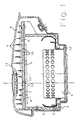
- Fig. 2 shows a view of the one-piece Plastic component, the housing 4, the intermediate cover 5 and the Areas 8 ′, 8 ′′ of the actuating element 8 that can be folded inwards includes.
- the intermediate cover 5 is one across the Provided breaking line 13 extending the housing width.
- the edges 10 ', 10' ' have slots 11', 11 '' so that they are in one another are pluggable, the edges 10 ', 10' 'on both sides of the Center are arranged alternately overlapping.
- FIG. 3 the embodiment of FIG. 1 is in two modules shown divided.
- the first assembly includes the cap 6 with breaking line 14 and integrated vehicle emblem 17.
- Die Cover cap 6 is made of plastic and has in itself in a known manner, edge-shaped webs or the like. About which they is connectable to the second assembly.
- the second assembly comprises the gas generator 1, the gas bag 2, the mounting plate 3 and the housing 4 with mounting opening 12 for the Gas generator 1.
- the housing 4 is made of Made of plastic and with the integral cover 5 and sections 8 ', 8 "of the actuating element 8 fitted.
- the intermediate cover is the one already mentioned Break line 13 is provided.
- the sections 8 ', 8' ' are in the Formed in a plane with the intermediate cover 5 and later folded along the fold lines 16 by 180 °, so that the actuating knobs 15 of the horn foil 7 and the one-piece molded Spacers 9 of the cover cap 6 are opposite, as in FIG. 1 seen.
Landscapes
- Engineering & Computer Science (AREA)
- Mechanical Engineering (AREA)
- Physics & Mathematics (AREA)
- Acoustics & Sound (AREA)
- Air Bags (AREA)
- Steering Controls (AREA)
Description
Claims (13)
- Airbagmodul für ein Kraftfahrzeuglenkrad mit einem Gasgenerator (1) mit Zünder, einem zusammengefalteten Gassack (2), einem Montageblech (3), einem Gehäuse (4) mit Zwischenabdeckung (5), einer äußeren, an die Lenkradumgebung optisch und haptisch angepaßten Abdeckkappe (6) sowie mit einer durch Druck auf die Abdeckkappe (6) zu betätigenden Hupenfolie (7), wobei zwischen der Hupenfolie (7) und der Abdeckkappe (6) ein flächiges Betätigungselement (8) aus Kunststoff vorgesehen ist, das in definiertem, überall gleichem Abstand zu der sich im wesentlichen in einer Ebene erstreckenden Hupenfolie (7) angeordnet ist, wobei zwischen dem Betätigungselement (8) und der Abdeckkappe (6) Abstandshalter (9) in Form von Stiften oder Stegen vorgesehen sind, um zwischen dem Betätigungselement (8) und der Abdeckkappe (6) zumindest über den gesamten Betätigungsbereich überall etwa gleich große Betätigungsabstände zu schaffen, und wobei die Abstandshalter (9) einstückig mit dem Betätigungselement (8) ausgebildet sind.
- Airbagmodul nach Anspruch 1, dadurch gekennzeichnet, daß die Zwischenabdeckung (5) aus Kunststoff besteht und daß das Betätigungselement (8) einstückig mit der Zwischenabdeckung (5) ausgebildet und durch Umklappen um 180° in die Montageendposition bringbar ist.
- Airbagmodul nach Anspruch 2, dadurch gekennzeichnet, daß das Betätigungselement (8) aus zwei flächigen Abschnitten (8', 8'') besteht, die an zwei gegenüberliegenden Seiten der Zwischenabdeckung (5) angeformt sind und deren äußere Ränder (10', 10'') nach dem Umklappen um 180° miteinander verbindbar sind.
- Airbagmodul nach Anspruch 3, dadurch gekennzeichnet, daß die äußeren Ränder (10', 10'') in der Montageendposition einander überlappend angeordnet sind.
- Airbagmodul nach Anspruch 4, dadurch gekennzeichnet, daß die äußeren Ränder (10', 10'') etwa in der Mitte je einen sich senkrecht nach innen erstreckenden Schlitz (11', 11'') aufweisen und daß die Ränder (10', 10'') über die Schlitze (11', 11'') derart ineinander steckbar sind, daß die Ränder (10', 10'') zu beiden Seiten von der Mitte alternierend überlappend angeordnet sind.
- Airbagmodul nach Anspruch 5, dadurch gekennzeichnet, daß an den Rändern der flächigen Abschnitte mehrere Steckschlitze und dementsprechend mehrere alternierende Überlappungsbereiche vorgesehen sind.
- Airbagmodul nach einem der Ansprüche 1 bis 6, dadurch gekennzeichnet, daß das Gehäuse (4) aus Kunststoff besteht und daß die Zwischenabdeckung (5) einstückig mit dem Gehäuse (4) ausgebildet ist.
- Airbagmodul nach Anspruch 7, dadurch gekennzeichnet, daß die Rückwand des Gehäuses (4) eine Aufnahmeöffnung (12) für den Gasgenerator (1) aufweist und daß die Zwischenabdeckung (5) mit einer Sollbruchlinie (13) ausgestattet ist.
- Airbagmodul nach einem der Ansprüche 1 bis 8, dadurch gekennzeichnet, daß die Hupenfolie (7) sich über die Zwischenabdeckung (5) erstreckend angeordnet und randseitig an der Zwischenabdeckung (5) und/oder am Gehäuse (4) befestigt ist.
- Airbagrnodul nach einem der Ansprüche 1 bis 9, dadurch gekennzeichnet, daß die Abdeckkappe (6) eine Sollbruchlinie (14) aufweist und randseitig mit dem Gehäuse (4) und/oder mit dem Montageblech (3) verbunden ist.
- Airbagmodul nach einem der Ansprüche 1 bis 10, dadurch gekennzeichnet, daß das Montageblech (3) zur Aufnahme des Gasgenerators (1) und zur Befestigung des Airbag-Moduls im Lenkrad ausgebildet ist.
- Airbagmodul nach einem der Ansprüche 1 bis 11, dadurch gekennzeichnet, daß sich Zwischenabdeckung (5), Hupenfolie (7) und Betätigungselement (8) im wesentlichen über die gesamte unterhalb der Abdeckkappe (6) verfügbare Fläche erstrecken.
- Airbagmodul nach einem der Ansprüche 1 bis 12, dadurch gekennzeichnet, daß die im Montageendzustand der Hupenfolie (7) zugewandte Oberfläche des Betätigungselements (8) mit voneinander gleichmäßig beabstandeten Betätigungsnoppen (15) ausgestattet ist.
Applications Claiming Priority (2)
| Application Number | Priority Date | Filing Date | Title |
|---|---|---|---|
| DE29813240U | 1998-07-24 | ||
| DE29813240U DE29813240U1 (de) | 1998-07-24 | 1998-07-24 | Airbagmodul mit Hupenfolie |
Publications (3)
| Publication Number | Publication Date |
|---|---|
| EP0974499A2 EP0974499A2 (de) | 2000-01-26 |
| EP0974499A3 EP0974499A3 (de) | 2002-10-30 |
| EP0974499B1 true EP0974499B1 (de) | 2004-09-15 |
Family
ID=8060359
Family Applications (1)
| Application Number | Title | Priority Date | Filing Date |
|---|---|---|---|
| EP99114156A Expired - Lifetime EP0974499B1 (de) | 1998-07-24 | 1999-07-21 | Airbagmodul mit Hupenfolie |
Country Status (5)
| Country | Link |
|---|---|
| US (1) | US6176516B1 (de) |
| EP (1) | EP0974499B1 (de) |
| JP (1) | JP2000043667A (de) |
| DE (2) | DE29813240U1 (de) |
| ES (1) | ES2229594T3 (de) |
Families Citing this family (6)
| Publication number | Priority date | Publication date | Assignee | Title |
|---|---|---|---|---|
| JP3760727B2 (ja) * | 2000-06-12 | 2006-03-29 | 豊田合成株式会社 | オーナメントを備えたエアバッグカバー |
| JP3900005B2 (ja) * | 2002-05-14 | 2007-04-04 | 豊田合成株式会社 | オーナメントを備えたエアバッグカバー |
| US6758489B2 (en) * | 2002-10-11 | 2004-07-06 | Key Safety Systems, Inc. | Inflator used as damper for steering wheel |
| DE202004017029U1 (de) * | 2004-11-04 | 2005-03-24 | Trw Automotive Safety Sys Gmbh | Fahrzeuginnenverkleidungsteil mit Airbagabdeckung |
| JP5357712B2 (ja) * | 2009-11-18 | 2013-12-04 | 日本プラスト株式会社 | エアバッグ装置 |
| NZ593354A (en) | 2011-06-09 | 2012-01-12 | Axip Ltd | Crushable impact absorbing road barrier |
Family Cites Families (14)
| Publication number | Priority date | Publication date | Assignee | Title |
|---|---|---|---|---|
| JPH0582709U (ja) | 1992-04-13 | 1993-11-09 | 豊田合成株式会社 | エアバッグ装置のパッド |
| JP3163747B2 (ja) | 1992-06-01 | 2001-05-08 | 豊田合成株式会社 | ステアリングホイールのパッド |
| US5265904A (en) | 1993-01-07 | 1993-11-30 | Ford Motor Company | Airbag cover with integral horn switch |
| JP2766775B2 (ja) * | 1993-03-23 | 1998-06-18 | ティーアールダブリュー・ヴィークル・セーフティ・システムズ・インコーポレーテッド | ハウジング組立体及び装置 |
| JP3252169B2 (ja) | 1993-04-27 | 2002-01-28 | 豊田合成株式会社 | ステアリングホイールのパッド |
| US5569893A (en) | 1995-04-10 | 1996-10-29 | Takata Inc. | Driver air bag cover with integral horn and redundant switches |
| DE69612785T2 (de) | 1995-04-28 | 2001-11-15 | Toyoda Gosei Co., Ltd. | Lenkrad mit einer Airbagvorrichtung |
| US5642901A (en) | 1995-05-26 | 1997-07-01 | Larry J. Winget | Thermoplastic air bag cover having a membrane switch with enhanced activation |
| US5639114A (en) | 1995-11-14 | 1997-06-17 | Trw Inc. | Steering wheel with air bag cover and horn switch |
| US5630617A (en) | 1996-01-02 | 1997-05-20 | Toyoda Gosei Co., Ltd. | Horn pad for a steering wheel |
| DE19622863A1 (de) * | 1996-06-07 | 1997-12-11 | Opel Adam Ag | Airbagmodul mit Hupenschalter |
| DE29612556U1 (de) * | 1996-07-19 | 1996-11-14 | Trw Occupant Restraint Systems Gmbh, 73551 Alfdorf | Gassack-Modul |
| US6047984A (en) | 1998-04-06 | 2000-04-11 | Larry J. Winget | Air bag cover and method of making same |
| US6079734A (en) | 1998-11-23 | 2000-06-27 | Larry J. Winget | Air bag cover assembly having a switch module and method of making same |
-
1998
- 1998-07-24 DE DE29813240U patent/DE29813240U1/de not_active Expired - Lifetime
-
1999
- 1999-07-21 ES ES99114156T patent/ES2229594T3/es not_active Expired - Lifetime
- 1999-07-21 EP EP99114156A patent/EP0974499B1/de not_active Expired - Lifetime
- 1999-07-21 DE DE59910493T patent/DE59910493D1/de not_active Expired - Fee Related
- 1999-07-22 US US09/359,007 patent/US6176516B1/en not_active Expired - Fee Related
- 1999-07-26 JP JP11210082A patent/JP2000043667A/ja not_active Withdrawn
Also Published As
| Publication number | Publication date |
|---|---|
| DE59910493D1 (de) | 2004-10-21 |
| ES2229594T3 (es) | 2005-04-16 |
| EP0974499A3 (de) | 2002-10-30 |
| EP0974499A2 (de) | 2000-01-26 |
| DE29813240U1 (de) | 1998-10-01 |
| JP2000043667A (ja) | 2000-02-15 |
| US6176516B1 (en) | 2001-01-23 |
Similar Documents
| Publication | Publication Date | Title |
|---|---|---|
| DE69416901T2 (de) | Fahrerseitiger Luftsackmodul-Deckel und Hupenschalter | |
| DE69610555T2 (de) | Thermoplastische airbag abdeckung mit multifunktionellem, gewölbten schaltmodul | |
| DE4310625C2 (de) | Airbageinrichtung mit einem als Membranschalter ausgebildeten Hupenschalter | |
| DE4242157B4 (de) | Modulabdeckung für ein Airbagsystem | |
| DE69611566T2 (de) | Lenkrad mit einbegriffener Luftsackeinheit | |
| EP1426237B1 (de) | Bauteil zum Einbau in geringem Abstand unter der äusseren Karosseriehaut eines Kraftfahrzeuges im Fussgängeraufprallbereich | |
| DE19614078A1 (de) | Abdeckung für ein fahrerseitiges Airbagmodul | |
| EP2323872A2 (de) | Gassackmodul für ein fahrzeuginsassen-rückhaltesystem | |
| EP0803410A2 (de) | Airbag-Abdeckkappe | |
| DE19829755B4 (de) | Airbagvorrichtung für ein Kraftfahrzeug | |
| DE4326368A1 (de) | Airbag-Vorrichtung | |
| DE69604295T2 (de) | Thermoplastische luftsackabdeckung, die einen membranschalter mit verbesserter betätigung besitzt | |
| EP0974499B1 (de) | Airbagmodul mit Hupenfolie | |
| EP1043199B1 (de) | Lenkrad mit Airbagmodul und Hupkontakt | |
| DE69700079T2 (de) | Brechbares Entlastungsbrückenglied für eine Hupenschaltung | |
| DE60132715T2 (de) | Airbag-modul mit hupenschalter | |
| EP3833581B1 (de) | Abdeckkappe für ein gassackmodul sowie gassackmodul mit einer solchen abdeckkappe | |
| EP1024061B1 (de) | Verbindung zwischen Generatorträger und Abdeckkappe in einem Airbagmodul | |
| EP0618110B1 (de) | Armaturentafel mit Beifahrer-Airbag | |
| EP0983913B1 (de) | Luftsack und Luftsackbefestigung | |
| DE4140275C2 (de) | Fahrzeug-Lenkrad mit einer Hupenbetätigung | |
| DE4438195C1 (de) | Lenkrad für ein Kraftfahrzeug | |
| EP1573763A1 (de) | Vorrichtung zur betätigung von elektrischen funktionsgruppen, insbesondere von hupen an lenkrädern von kraftfahrzeugen | |
| EP0975058B1 (de) | Kontaktvorrichtung | |
| DE69610876T2 (de) | Deckel mit Funktionsschaltern für Fahrerseite-Airbag |
Legal Events
| Date | Code | Title | Description |
|---|---|---|---|
| PUAI | Public reference made under article 153(3) epc to a published international application that has entered the european phase |
Free format text: ORIGINAL CODE: 0009012 |
|
| AK | Designated contracting states |
Kind code of ref document: A2 Designated state(s): AT BE CH CY DE DK ES FI FR GB GR IE IT LI LU MC NL PT SE |
|
| AX | Request for extension of the european patent |
Free format text: AL;LT;LV;MK;RO;SI |
|
| PUAL | Search report despatched |
Free format text: ORIGINAL CODE: 0009013 |
|
| AK | Designated contracting states |
Kind code of ref document: A3 Designated state(s): AT BE CH CY DE DK ES FI FR GB GR IE IT LI LU MC NL PT SE |
|
| AX | Request for extension of the european patent |
Free format text: AL;LT;LV;MK;RO;SI |
|
| 17P | Request for examination filed |
Effective date: 20030409 |
|
| AKX | Designation fees paid |
Designated state(s): DE ES FR GB IT |
|
| 17Q | First examination report despatched |
Effective date: 20030610 |
|
| GRAP | Despatch of communication of intention to grant a patent |
Free format text: ORIGINAL CODE: EPIDOSNIGR1 |
|
| RAP1 | Party data changed (applicant data changed or rights of an application transferred) |
Owner name: TRW AUTOMOTIVE SAFETY SYSTEMS GMBH |
|
| GRAS | Grant fee paid |
Free format text: ORIGINAL CODE: EPIDOSNIGR3 |
|
| GRAA | (expected) grant |
Free format text: ORIGINAL CODE: 0009210 |
|
| AK | Designated contracting states |
Kind code of ref document: B1 Designated state(s): DE ES FR GB IT |
|
| REG | Reference to a national code |
Ref country code: GB Ref legal event code: FG4D Free format text: NOT ENGLISH |
|
| REG | Reference to a national code |
Ref country code: IE Ref legal event code: FG4D Free format text: GERMAN |
|
| REF | Corresponds to: |
Ref document number: 59910493 Country of ref document: DE Date of ref document: 20041021 Kind code of ref document: P |
|
| GBT | Gb: translation of ep patent filed (gb section 77(6)(a)/1977) |
Effective date: 20041201 |
|
| REG | Reference to a national code |
Ref country code: ES Ref legal event code: FG2A Ref document number: 2229594 Country of ref document: ES Kind code of ref document: T3 |
|
| REG | Reference to a national code |
Ref country code: IE Ref legal event code: FD4D |
|
| PGFP | Annual fee paid to national office [announced via postgrant information from national office to epo] |
Ref country code: GB Payment date: 20050614 Year of fee payment: 7 |
|
| PGFP | Annual fee paid to national office [announced via postgrant information from national office to epo] |
Ref country code: FR Payment date: 20050706 Year of fee payment: 7 |
|
| PGFP | Annual fee paid to national office [announced via postgrant information from national office to epo] |
Ref country code: ES Payment date: 20050715 Year of fee payment: 7 |
|
| PLBE | No opposition filed within time limit |
Free format text: ORIGINAL CODE: 0009261 |
|
| STAA | Information on the status of an ep patent application or granted ep patent |
Free format text: STATUS: NO OPPOSITION FILED WITHIN TIME LIMIT |
|
| ET | Fr: translation filed | ||
| 26N | No opposition filed |
Effective date: 20050616 |
|
| PG25 | Lapsed in a contracting state [announced via postgrant information from national office to epo] |
Ref country code: GB Free format text: LAPSE BECAUSE OF NON-PAYMENT OF DUE FEES Effective date: 20060721 |
|
| PGFP | Annual fee paid to national office [announced via postgrant information from national office to epo] |
Ref country code: IT Payment date: 20060731 Year of fee payment: 8 |
|
| GBPC | Gb: european patent ceased through non-payment of renewal fee |
Effective date: 20060721 |
|
| REG | Reference to a national code |
Ref country code: FR Ref legal event code: ST Effective date: 20070330 |
|
| REG | Reference to a national code |
Ref country code: ES Ref legal event code: FD2A Effective date: 20060722 |
|
| PG25 | Lapsed in a contracting state [announced via postgrant information from national office to epo] |
Ref country code: ES Free format text: LAPSE BECAUSE OF NON-PAYMENT OF DUE FEES Effective date: 20060722 |
|
| PG25 | Lapsed in a contracting state [announced via postgrant information from national office to epo] |
Ref country code: FR Free format text: LAPSE BECAUSE OF NON-PAYMENT OF DUE FEES Effective date: 20060731 |
|
| PGFP | Annual fee paid to national office [announced via postgrant information from national office to epo] |
Ref country code: DE Payment date: 20080731 Year of fee payment: 10 |
|
| PG25 | Lapsed in a contracting state [announced via postgrant information from national office to epo] |
Ref country code: IT Free format text: LAPSE BECAUSE OF NON-PAYMENT OF DUE FEES Effective date: 20070721 |
|
| PG25 | Lapsed in a contracting state [announced via postgrant information from national office to epo] |
Ref country code: DE Free format text: LAPSE BECAUSE OF NON-PAYMENT OF DUE FEES Effective date: 20100202 |