EP0974508A2 - Système de direction pour machines de travail automoteurs et tracteurs - Google Patents
Système de direction pour machines de travail automoteurs et tracteurs Download PDFInfo
- Publication number
- EP0974508A2 EP0974508A2 EP99114041A EP99114041A EP0974508A2 EP 0974508 A2 EP0974508 A2 EP 0974508A2 EP 99114041 A EP99114041 A EP 99114041A EP 99114041 A EP99114041 A EP 99114041A EP 0974508 A2 EP0974508 A2 EP 0974508A2
- Authority
- EP
- European Patent Office
- Prior art keywords
- steering
- switching
- hydraulic
- steering device
- valves
- Prior art date
- Legal status (The legal status is an assumption and is not a legal conclusion. Google has not performed a legal analysis and makes no representation as to the accuracy of the status listed.)
- Granted
Links
- 239000012530 fluid Substances 0.000 claims description 22
- 230000000903 blocking effect Effects 0.000 claims description 4
- 230000007257 malfunction Effects 0.000 claims description 4
- 230000001419 dependent effect Effects 0.000 claims description 2
- 238000010586 diagram Methods 0.000 description 9
- 238000006073 displacement reaction Methods 0.000 description 3
- 238000010276 construction Methods 0.000 description 2
- 208000010201 Exanthema Diseases 0.000 description 1
- 238000001816 cooling Methods 0.000 description 1
- 230000007547 defect Effects 0.000 description 1
- 230000002950 deficient Effects 0.000 description 1
- 201000005884 exanthem Diseases 0.000 description 1
- 238000005086 pumping Methods 0.000 description 1
- 206010037844 rash Diseases 0.000 description 1
- 239000007787 solid Substances 0.000 description 1
Images


Classifications
-
- B—PERFORMING OPERATIONS; TRANSPORTING
- B62—LAND VEHICLES FOR TRAVELLING OTHERWISE THAN ON RAILS
- B62D—MOTOR VEHICLES; TRAILERS
- B62D7/00—Steering linkage; Stub axles or their mountings
- B62D7/06—Steering linkage; Stub axles or their mountings for individually-pivoted wheels, e.g. on king-pins
- B62D7/14—Steering linkage; Stub axles or their mountings for individually-pivoted wheels, e.g. on king-pins the pivotal axes being situated in more than one plane transverse to the longitudinal centre line of the vehicle, e.g. all-wheel steering
- B62D7/142—Steering linkage; Stub axles or their mountings for individually-pivoted wheels, e.g. on king-pins the pivotal axes being situated in more than one plane transverse to the longitudinal centre line of the vehicle, e.g. all-wheel steering specially adapted for particular vehicles, e.g. tractors, carts, earth-moving vehicles, trucks
-
- B—PERFORMING OPERATIONS; TRANSPORTING
- B62—LAND VEHICLES FOR TRAVELLING OTHERWISE THAN ON RAILS
- B62D—MOTOR VEHICLES; TRAILERS
- B62D5/00—Power-assisted or power-driven steering
- B62D5/06—Power-assisted or power-driven steering fluid, i.e. using a pressurised fluid for most or all the force required for steering a vehicle
- B62D5/30—Safety devices, e.g. alternate emergency power supply or transmission means to ensure steering upon failure of the primary steering means
Definitions
- the invention relates to a steering device for self-driving Working machines and tractors with one pair of wheels each associated steering cylinders, which a fluid from a Valve unit can be fed and with at least one hydraulic pump, the hydraulic lines with the valve unit are connected.
- EP 0 439 370 B1 is a steering device for self-driving Known machines with a steering control unit, those for setting different types of steering, for example Front and all-wheel steering, a number of has electromagnetically actuated directional valves.
- a first one Control valve enables switching between front wheel and all-wheel steering.
- a second downstream control valve enables the setting of two different all-wheel steering types.
- the steering control unit is used to provide the fluid connected to a hydraulic pump.
- a disadvantage of the known steering device is that in the event of a power failure, pump failure or other malfunctions no precautions have been taken to control the Maintain work machine.
- a steering device for self-propelled work machines known with a steering control unit two hydraulic pumps are connected. That of the respective Hydraulic pumped fluid is used in a common Hydraulic line merged before the steering control unit is fed.
- the hydraulic pumps are different designed, with a first hydraulic pump in normal operation first put into operation with a higher capacity and the second hydraulic pump as a slave pump only then is switched on as soon as the pumping first hydraulic pump has reached the greatest possible flow.
- One pump can pump the fluid through the other Pump are guaranteed, being in the hydraulic lines built-in check valves a return of the Prevent fluids in the damaged branch of the delivery line.
- a disadvantage of the known steering device is that only one case of damage in one of the respective hydraulic pumps Detected near area of the delivery lines and thus a Steering can be maintained.
- the object of the invention is therefore a steering device for to further develop self-propelled machines and tractors, that at all times a safe control of work or Tractor is guaranteed.
- the invention is characterized in that that the valve unit one each a steering cylinder has associated switching unit with switching valves and that the switching valves automatically in a fault condition are so switchable that the steering cylinder over a single Steering control unit can be controlled.
- the particular advantage of the invention is that the Switching valves of the switching units are designed so that in the event of damage or in the fault condition of the steering device are automatically switched to a position in which the steering cylinders only with a single steering control unit stay in contact. It is preferably in the fault state a first switching unit in the locked position while the switching valves of a second switching unit switched in this way are that the steering cylinder in succession with the Fluid are applied.
- the switching unit between the steering control unit and the one assigned to it Steering cylinder arranged. This will result in a damage Ensure switching to a safe state, taking a Hydraulic circuit with its defective components can be switched off completely.
- the is in the fault state switching unit connected to the steering cylinders with only a hydraulic device Steering control unit connected so that in the event of damage safe condition is achieved.
- the steering cylinders by means of the switching valves of the switching unit in an all-wheel steering mode switched.
- the steering device of two hydraulic circuits one of which is in Steering cylinder assigned to the direction of travel of the front axle hydraulic steering control unit and one in the direction of travel steering axle of an electro-hydraulic rear axle Steering control unit is assigned.
- This allows the steering cylinders assigned to the rear axle in a simple manner electrically according to a steering program that of the front Steering cylinders assigned to the axle can be readjusted.
- Through the parallel control of the steering cylinder and the electrical controllability of a steering control unit several steering types or types can be realized variably.
- the switching valves the switching units as directly switched seat valves designed to be without supply of electrical energy can be brought into the position specified for the fault condition are.
- the switching valves the first and second switching units can be interconnected in such a way that both the first steering cylinder and the second steering cylinder of the front axle or the rear axle can be assigned to the machine. This will Allows the front axle to be controlled by a hydraulic Valve controlled by specifying a steering setpoint with the rear axle depending on the steering setpoint is tracked according to a specific steering program.
- the emergency steering pump formed as a constant pump, which depending on the Driving speed of the working machine is operated. It a simple construction of the emergency steering pump can thus be realized.
- the steering cylinder each by means of electromagnetically actuated control valves controlled, while a hydraulic connected to a steering wheel Set up as a steering angle setpoint sensor according to a Steering program controls one or two of these control valves. In this way it becomes a purely hydraulic control the steering cylinder matches steering behavior or steering feel generated by the driver.
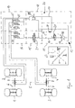
- a work machine four wheels (1, 2, 3, 4), each in pairs at the ends a longitudinal axis (5) of the working machine are arranged.
- wheels (1) and (2) form a pair of wheels in the direction of travel front axle (6) and the wheels (3) and (4) a pair of wheels of a rear axle in the direction of travel (7).
- a double-acting first steering cylinder (8) and for actuating the wheels (1 and 2) a double-acting second steering cylinder (9) is provided.
- the steering cylinders (8) and (9) are each via hydraulic lines connected to a valve unit.
- the valve unit consists of one or more steering control and switching units. It is connected to a supply unit (11) which has a hydraulic pump (12).
- the hydraulic pump is in the normal operating state of the steering device (12) via a first delivery line (14) with a first steering control unit (15), with an adjoining one first switching unit (16) and with the first Steering cylinder (8) connected (first hydraulic circuit 13).
- the hydraulic pump (12) is also connected via a second delivery line (17) with a second steering control unit (18), with an adjoining second switching unit (19) and connected to the second steering cylinder (9) (second hydraulic circuit 26).
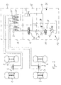
- the supply unit (11) has a hydraulic pump (12) downstream control valve (20), which is in an operating position both steering control units (15) and (18) with acted upon the fluid, while - as shown in Figure 2 - only one connection in the fault condition position the hydraulic pump (12) to the second steering control unit (18) enables.
- the first steering control unit (15) consists of an electromagnetically actuated valve (21), which is preferably designed as a proportional valve.
- the second steering control unit (18) has a hydraulic device (22) (also called orbitrol in specialist circles), which is in operative connection with a steering wheel (not shown) and, according to the solid characteristic curve shown in Figure 1, causes a steering angle for the front axle (6).
- the steering cylinder (8) of the rear axle (7) is controlled by means of the proportional valve (21) in accordance with a characteristic curve drawn in dashed lines in the diagram. It is possible to select several steering programs for the electro-hydraulic steering of the rear axle (7).
- a characteristic curve Road trip "(23) can be selected which, when the front axle (6) is pivoted in one direction of rotation, causes the rear axle (7) to be pivoted in the opposite direction.
- all-wheel steering can be set, which on the one hand enables the front axle (6) and rear axle (7) (crab walk) to be parallel and on the other hand enables tight steering as described in the characteristic curve with a small turning circle of the working machine .
- the switching units (16) and (19) each have switching valves (24) or (25), which each occupy two switching positions can.
- the two are in the operating state according to FIG. 1 Switching valves (24) of the first switching unit (16) in Forward direction switched.
- the second switching unit (19) has three switching valves (25, 25 '), a first of which Switch valve (25) in the open position and the other two Switching valves (25 ') are switched into the blocking position.
- the first Switch valve (25) switched in the open position is on the one hand with the hydraulic valve (22) and on the other via hydraulic lines with the second steering cylinder (9) and the further switching valve (25 ') connectable.
- the switching valve (25 ') located in the blocking position with the hydraulic valve (22) and the other with the first Steering cylinder (8) connected.
- the third, in the locked position Switch valve (25 ') is with the other connection of the first steering cylinder (8) on the one hand and in the open position located first switching valve (25) connected.
- the switching valves (24) and (25, 25 ') automatically in switched a second switching position according to Figure 2.
- the switching valves (24, 25, 25 ') are electromagnetic Actuable 2/2-way valves are formed, each via a Return spring switchable into the switching position according to Figure 2 are. The switchover takes place without electrical supply Energy, so that in the event of a fault, a safe state the steering device is guaranteed.
- FIG second hydraulic circuit (26) with a second supply unit (27) can be activated.
- This supply unit (27) has an emergency steering pump (28) which is operated by an unillustrated part firmly connected to the wheels of the working machine of the drive train is driven.
- the emergency steering pump (28) is preferably designed as a constant pump, for example as a gear pump a speed-dependent Provides funding.
- the emergency steering pump (28) has two delivery directions and is via a pressure relief valve (29) protected against overload. Because the fluid in the second hydraulic circuit (26) by means of the emergency steering pump (28) is funded in the event of damage without interruption a cooler (30) is provided for cooling the fluid.
- the switching valves (24, 25, 25 ') are faulty Switching units (16) or (19) according to the first embodiment Fig. 1 and Fig. 2 switched, now that Fluid conveyed or provided by the emergency steering pump (28) and in succession via the hydraulic device (22) the steering cylinders (8) and (9) is fed.
- the control valve (20) can be controlled electromagnetically in such a way that at low driving speed at which the emergency steering pump (28) not the required funding volume for Control of the front axle (6) can apply the hydraulic Device (22) a partial fluid flow from the first hydraulic circuit (13) is branched off. The hydraulic device (22) is thus subjected to a constant fluid flow. Using load reporting lines (36) and shuttle valves (37) can the hydraulic pump (12) to a required Set operating pressure or delivery volume.
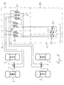
- FIG. 4 shows a third exemplary embodiment of the steering device, this is different from the first embodiment 1 and 2 modified switching units (16) or (19).
- the switching units (16) and (19) each have a double number of switching valves (24) or (25, 25 ') so that the delivery lines (14) and (17) can be assigned to different steering cylinders (8) and (9) are.
- This steering device is suitable for machines with two main directions, for example the front Axle (6) can be acted upon by the second steering control unit (18) is.
- a steering sense valve (31) provided that when the driver's cab is turned by 180 ° second delivery line (17) always with the front steering cylinder (9) connects. In this way, the front axle is always (6) by the hydraulic steering control unit (18) and the rear axle (7) by the electro-hydraulic steering control unit (15) controlled.
- This embodiment enables control the steering cylinder (8) and (9) each through a proportional valve (21, 21 ').
- the steering cylinders (8) and (9) are each through the proportional valves designed as 4/3-way valves (21) or (21 ') separately controllable. According to that in FIG. 5 Assuming a malfunction, the steering cylinders (8) and (9) actuated including the hydraulic device (22). According to this embodiment, the axes (6) and (7) controlled simultaneously via a control valve (21, 21 ') become.
- a fifth embodiment shown in Figure 6 are like in the previous embodiment, two proportional valves (21, 21 ') are provided, which in the operating state control enable the axes (6) and (7).
- the switching valves (25, 25 ') switched in such a way that the fluid bypassing the steering cylinder (8, 9) flows back directly to the hydraulic device (22).
- the hydraulic device (22) is thus virtually short-circuited , and that of the hydraulic device (22) displaced fluid flow therefore has no influence on the rash the wheels (1, 2, 3, 4). Consequently, the one with the hydraulic device (22) operatively connected steering wheel Steering wheel counter torque generated, that when activated the steering cylinder (8) and (9) by actuating the hydraulic Device (22) corresponds.
- the steering wheel can be used as a steering angle setpoint generator, the Driver of the machine perceives the same steering feeling.
- the purpose is the steering wheel with an electric encoder connected.
- the encoder can be designed as an incremental encoder be and be arranged on the steering shaft.
- the thus Setpoint generated controls accordingly according to a steering program the characteristic curve shown in Figure 1, the proportional valves (21, 21 ').
- one is Return line (32) of the hydraulic device (22) provided that is directly connected to the tank.
- FIG. 7 is different from the first embodiment 1 and 2, the second steering control unit (18) from one to that contained in the first steering control unit (15) Control valve (21) of identical construction control valve (21 ').
- the control valves (21, 21 ') are each via the hydraulic pump (12) acted upon.
- the paired switch Switching valves (33) and (33 ') of the first switching unit (16) or the second switching unit (19) in the blocking position.
- the three other switching valves (33 '') of the second Switching unit (19) switch automatically into a switching position, in which depending on the operation of a control valve (21) or (21 ') the steering cylinder (8, 9) in the already described Way, connected in series, one after the other with the fluid be charged.
- variable displacement pumps (34, 34 ') are each can be controlled proportionally and enable each other Independent control of the steering cylinder (8, 9).
- the steering can be used for damage or malfunction a single variable pump (34) or (34 ') corresponding to the previous embodiments are maintained, wherein the fluid from the corresponding variable displacement pump (34, 34 ') via the control valves (33 ', 33' ') to the steering cylinders (8, 9) to be led.
Landscapes
- Engineering & Computer Science (AREA)
- Chemical & Material Sciences (AREA)
- Combustion & Propulsion (AREA)
- Transportation (AREA)
- Mechanical Engineering (AREA)
- Power Steering Mechanism (AREA)
- Steering-Linkage Mechanisms And Four-Wheel Steering (AREA)
- Steering Control In Accordance With Driving Conditions (AREA)
Applications Claiming Priority (2)
| Application Number | Priority Date | Filing Date | Title |
|---|---|---|---|
| DE19833383 | 1998-07-24 | ||
| DE19833383A DE19833383A1 (de) | 1998-07-24 | 1998-07-24 | Lenkvorrichtung für selbstfahrende Arbeitsmaschinen und Zugmaschinen |
Publications (3)
| Publication Number | Publication Date |
|---|---|
| EP0974508A2 true EP0974508A2 (fr) | 2000-01-26 |
| EP0974508A3 EP0974508A3 (fr) | 2002-12-18 |
| EP0974508B1 EP0974508B1 (fr) | 2008-01-23 |
Family
ID=7875203
Family Applications (1)
| Application Number | Title | Priority Date | Filing Date |
|---|---|---|---|
| EP99114041A Expired - Lifetime EP0974508B1 (fr) | 1998-07-24 | 1999-07-20 | Système de direction pour machines de travail automoteurs et tracteurs |
Country Status (3)
| Country | Link |
|---|---|
| US (1) | US6374940B1 (fr) |
| EP (1) | EP0974508B1 (fr) |
| DE (2) | DE19833383A1 (fr) |
Cited By (3)
| Publication number | Priority date | Publication date | Assignee | Title |
|---|---|---|---|---|
| WO2009083220A1 (fr) * | 2007-12-28 | 2009-07-09 | Robert Bosch Gmbh | Système de transmission hydrostatique à régénération |
| NL1037753C2 (nl) * | 2010-02-26 | 2011-08-29 | V S E Vehicle Systems Engineering B V | Voertuig voorzien van een noodstuurinrichting, combinatie van trekkend en getrokken voertuig, getrokken voertuig, en meestuurinrichting voor een voertuig. |
| EP4177135A1 (fr) * | 2021-11-09 | 2023-05-10 | CLAAS Selbstfahrende Erntemaschinen GmbH | Système de direction pour un véhicule de travail agricole |
Families Citing this family (14)
| Publication number | Priority date | Publication date | Assignee | Title |
|---|---|---|---|---|
| WO2002014136A2 (fr) * | 2000-08-15 | 2002-02-21 | Mtd Products Inc | Vehicule a rayon de braquage nul comportant un mecanisme a une pompe et deux moteurs |
| US7316288B1 (en) | 2003-01-27 | 2008-01-08 | Polaris Industries Inc. | All terrain vehicle with multiple steering modes |
| US7278511B1 (en) | 2003-01-27 | 2007-10-09 | Polaris Industries Inc. | Controller for steering a vehicle |
| JP2009502605A (ja) | 2005-07-22 | 2009-01-29 | インフィニトラク エルエルシー | ステアリングシステム、操向および速度調整システム、ならびに関連する車両 |
| DE102006028957B4 (de) * | 2006-06-23 | 2009-07-09 | Terex Demag Gmbh | Hinterachslenkung für einen Fahrzeugkran |
| US7914022B2 (en) | 2006-10-17 | 2011-03-29 | Mtd Products Inc | Vehicle control systems and methods |
| US8136613B2 (en) | 2008-03-26 | 2012-03-20 | Mtd Products Inc | Vehicle control systems and methods |
| US8676445B2 (en) * | 2010-04-27 | 2014-03-18 | Ford Global Technologies, Llc | Hydraulic steering diagnostic system and method |
| MX367526B (es) | 2011-09-22 | 2019-08-26 | Mtd Products Inc | Sistemas y métodos de control de vehículo y vehículos relacionados. |
| US20150198507A1 (en) * | 2014-01-15 | 2015-07-16 | Caterpillar, Inc. | Increased Pressure for Emergency Steering Pump Startup Test |
| EP2944540B1 (fr) * | 2014-05-20 | 2018-08-22 | Xuzhou Heavy Machinery Co., Ltd. | Système de braquage et véhicule à roues, à charge lourde ayant une suspension indépendante |
| US11702136B2 (en) * | 2019-09-18 | 2023-07-18 | Deere & Company | Reverse steering modes for agricultural vehicles |
| US11731690B2 (en) * | 2020-02-12 | 2023-08-22 | Caterpillar Inc. | Redundant steering system and machines and methods thereof |
| DE102021121139A1 (de) | 2021-08-13 | 2023-02-16 | Claas Selbstfahrende Erntemaschinen Gmbh | Lenksystem für ein landwirtschaftliches Fahrzeug |
Citations (2)
| Publication number | Priority date | Publication date | Assignee | Title |
|---|---|---|---|---|
| EP0439370B1 (fr) | 1990-01-25 | 1994-10-05 | J.C. Bamford Excavators Limited | Véhicule |
| WO1996001760A1 (fr) | 1994-07-08 | 1996-01-25 | O & K Orenstein & Koppel Ag | Procede d'actionnement des verins de braquage de machines de travail mobiles et systeme de direction pour machines de travail mobiles |
Family Cites Families (15)
| Publication number | Priority date | Publication date | Assignee | Title |
|---|---|---|---|---|
| US3730288A (en) * | 1970-12-09 | 1973-05-01 | Clark Equipment Co | Dual steering system |
| US4006664A (en) * | 1975-04-03 | 1977-02-08 | Pettibone Corporation | Steering system including tandem hydraulic cylinders with self-synchronization |
| DE2721556C2 (de) * | 1977-05-13 | 1987-05-14 | Zahnradfabrik Friedrichshafen Ag, 7990 Friedrichshafen | Hilfskraftlenkung für Kraftfahrzeuge |
| US4130177A (en) * | 1977-07-15 | 1978-12-19 | Pandolph James E | Ladder climber's safety device |
| JPS6234861A (ja) * | 1985-08-06 | 1987-02-14 | Nissan Motor Co Ltd | 車両の4輪操舵装置 |
| DE3619330C2 (de) * | 1985-09-16 | 1997-12-04 | Zahnradfabrik Friedrichshafen | Hilfskraftlenkung für Kraftfahrzeuge |
| US4723475A (en) * | 1986-09-29 | 1988-02-09 | Deere & Company | Fully metered compensation steering system |
| DE3833421C1 (fr) * | 1988-10-01 | 1990-01-11 | Daimler-Benz Aktiengesellschaft, 7000 Stuttgart, De | |
| DE3833420C1 (en) * | 1988-10-01 | 1989-12-28 | Daimler-Benz Aktiengesellschaft, 7000 Stuttgart, De | All-wheel steering system |
| US5249639A (en) * | 1992-07-24 | 1993-10-05 | Caterpillar Inc. | Steering control arrangement |
| JP3099554B2 (ja) * | 1992-09-17 | 2000-10-16 | 株式会社豊田自動織機製作所 | 四輪操舵装置 |
| DE4301745C1 (de) * | 1993-01-23 | 1994-06-23 | Orenstein & Koppel Ag | Verfahren zur Steuerung des Lenkverhaltens einer mobilen Baumaschine sowie Lenkung für die Baumaschine |
| US5609221A (en) * | 1995-03-06 | 1997-03-11 | Caterpillar Inc. | Steering control system |
| US5526891A (en) * | 1995-03-31 | 1996-06-18 | Caterpillar Inc. | Steering control arrangement |
| DE19531413B4 (de) * | 1995-08-26 | 2007-09-20 | Bosch Rexroth Aktiengesellschaft | Anordnung zur Versorgung der hydraulischen Lenkung eines Kraftfahrzeugs |
-
1998
- 1998-07-24 DE DE19833383A patent/DE19833383A1/de not_active Withdrawn
-
1999
- 1999-07-20 DE DE59914618T patent/DE59914618D1/de not_active Expired - Lifetime
- 1999-07-20 EP EP99114041A patent/EP0974508B1/fr not_active Expired - Lifetime
- 1999-07-23 US US09/360,079 patent/US6374940B1/en not_active Expired - Fee Related
Patent Citations (2)
| Publication number | Priority date | Publication date | Assignee | Title |
|---|---|---|---|---|
| EP0439370B1 (fr) | 1990-01-25 | 1994-10-05 | J.C. Bamford Excavators Limited | Véhicule |
| WO1996001760A1 (fr) | 1994-07-08 | 1996-01-25 | O & K Orenstein & Koppel Ag | Procede d'actionnement des verins de braquage de machines de travail mobiles et systeme de direction pour machines de travail mobiles |
Cited By (4)
| Publication number | Priority date | Publication date | Assignee | Title |
|---|---|---|---|---|
| WO2009083220A1 (fr) * | 2007-12-28 | 2009-07-09 | Robert Bosch Gmbh | Système de transmission hydrostatique à régénération |
| NL1037753C2 (nl) * | 2010-02-26 | 2011-08-29 | V S E Vehicle Systems Engineering B V | Voertuig voorzien van een noodstuurinrichting, combinatie van trekkend en getrokken voertuig, getrokken voertuig, en meestuurinrichting voor een voertuig. |
| EP2361821A1 (fr) | 2010-02-26 | 2011-08-31 | V.S.E. Vehicle Systems Engineering B.V. | Véhicule et ensemble véhicule tracteur et véhicule remorque comprenant un système de direction principal et un système de direction auxiliaire avec un système de direction de secours |
| EP4177135A1 (fr) * | 2021-11-09 | 2023-05-10 | CLAAS Selbstfahrende Erntemaschinen GmbH | Système de direction pour un véhicule de travail agricole |
Also Published As
| Publication number | Publication date |
|---|---|
| EP0974508B1 (fr) | 2008-01-23 |
| US6374940B1 (en) | 2002-04-23 |
| EP0974508A3 (fr) | 2002-12-18 |
| DE19833383A1 (de) | 2000-01-27 |
| DE59914618D1 (de) | 2008-03-13 |
Similar Documents
| Publication | Publication Date | Title |
|---|---|---|
| EP0974508B1 (fr) | Système de direction pour machines de travail automoteurs et tracteurs | |
| EP0898539B1 (fr) | Mecanisme de direction de vehicule | |
| DE19546733C1 (de) | Hydraulische Servolenkung | |
| DE3876003T2 (de) | Vierradlenkung fuer ein kraftfahrzeug. | |
| DE60004111T2 (de) | Kraftübertragung für ein fahrbares Gerät mit mindestens zwei angetriebenen Achsen | |
| DE1755297C3 (de) | Hydrostatische Hilfskraftlenkeinrichtung, insbesondere für schwere Fahrzeuge | |
| EP2999613B1 (fr) | Système de direction steer-by-wire électrohydraulique | |
| DE102005035171A1 (de) | Elektrohydraulische Lenkung | |
| EP2077958B1 (fr) | Vehicule utilitaire avec un dispositif de direction hydraulique | |
| EP0388634A1 (fr) | Dispositif d'antiblocage et de limitation du glissement de traction | |
| EP2753531B1 (fr) | Système de direction hydraulique | |
| DE19962124A1 (de) | Hydraulisches Zweikreis-Lenksystem | |
| EP4177135A1 (fr) | Système de direction pour un véhicule de travail agricole | |
| EP0746492B1 (fr) | Direction hydraulique a demultiplication variable | |
| DE102012018993A1 (de) | Landwirtschaftliches Fahrzeug mit Servolenkung | |
| DE2721556C2 (de) | Hilfskraftlenkung für Kraftfahrzeuge | |
| DE19855405A1 (de) | Hydraulische Servolenkung für Kraftfahrzeuge | |
| DE19935073A1 (de) | Steer-by-wire-Lenkung mit hydraulischem Druckspeicher | |
| DE2456473C3 (de) | Steuereinrichtung für einen hydrostatischen Fahrantrieb | |
| EP0236511B1 (fr) | Dispositif de commande hydraulique | |
| EP4134294A1 (fr) | Système de direction pour un véhicule agricole | |
| EP1542878B1 (fr) | Systeme de stabilisation hydraulique pour vehicules | |
| EP4178847A1 (fr) | Direction assistée hydraulique | |
| DE4031969C2 (de) | Zweikreis-Lenksystem für Kraftfahrzeuge | |
| WO2000077426A1 (fr) | Systeme d'entrainement hydrostatique |
Legal Events
| Date | Code | Title | Description |
|---|---|---|---|
| PUAI | Public reference made under article 153(3) epc to a published international application that has entered the european phase |
Free format text: ORIGINAL CODE: 0009012 |
|
| AK | Designated contracting states |
Kind code of ref document: A2 Designated state(s): AT BE CH CY DE DK ES FI FR GB GR IE IT LI LU MC NL PT SE |
|
| AX | Request for extension of the european patent |
Free format text: AL;LT;LV;MK;RO;SI |
|
| PUAL | Search report despatched |
Free format text: ORIGINAL CODE: 0009013 |
|
| AK | Designated contracting states |
Kind code of ref document: A3 Designated state(s): AT BE CH CY DE DK ES FI FR GB GR IE IT LI LU MC NL PT SE |
|
| AX | Request for extension of the european patent |
Free format text: AL;LT;LV;MK;RO;SI |
|
| 17P | Request for examination filed |
Effective date: 20030618 |
|
| AKX | Designation fees paid |
Designated state(s): BE DE FR GB IT |
|
| 17Q | First examination report despatched |
Effective date: 20041221 |
|
| 17Q | First examination report despatched |
Effective date: 20041221 |
|
| 17Q | First examination report despatched |
Effective date: 20041221 |
|
| GRAP | Despatch of communication of intention to grant a patent |
Free format text: ORIGINAL CODE: EPIDOSNIGR1 |
|
| GRAS | Grant fee paid |
Free format text: ORIGINAL CODE: EPIDOSNIGR3 |
|
| GRAA | (expected) grant |
Free format text: ORIGINAL CODE: 0009210 |
|
| AK | Designated contracting states |
Kind code of ref document: B1 Designated state(s): BE DE FR GB IT |
|
| REG | Reference to a national code |
Ref country code: GB Ref legal event code: FG4D Free format text: NOT ENGLISH |
|
| REF | Corresponds to: |
Ref document number: 59914618 Country of ref document: DE Date of ref document: 20080313 Kind code of ref document: P |
|
| GBT | Gb: translation of ep patent filed (gb section 77(6)(a)/1977) |
Effective date: 20080319 |
|
| ET | Fr: translation filed | ||
| PLBE | No opposition filed within time limit |
Free format text: ORIGINAL CODE: 0009261 |
|
| STAA | Information on the status of an ep patent application or granted ep patent |
Free format text: STATUS: NO OPPOSITION FILED WITHIN TIME LIMIT |
|
| 26N | No opposition filed |
Effective date: 20081024 |
|
| PG25 | Lapsed in a contracting state [announced via postgrant information from national office to epo] |
Ref country code: IT Free format text: LAPSE BECAUSE OF FAILURE TO SUBMIT A TRANSLATION OF THE DESCRIPTION OR TO PAY THE FEE WITHIN THE PRESCRIBED TIME-LIMIT Effective date: 20080123 |
|
| PG25 | Lapsed in a contracting state [announced via postgrant information from national office to epo] |
Ref country code: BE Free format text: LAPSE BECAUSE OF NON-PAYMENT OF DUE FEES Effective date: 20080731 |
|
| PGFP | Annual fee paid to national office [announced via postgrant information from national office to epo] |
Ref country code: GB Payment date: 20140721 Year of fee payment: 16 |
|
| REG | Reference to a national code |
Ref country code: FR Ref legal event code: PLFP Year of fee payment: 17 |
|
| PGFP | Annual fee paid to national office [announced via postgrant information from national office to epo] |
Ref country code: FR Payment date: 20150626 Year of fee payment: 17 |
|
| GBPC | Gb: european patent ceased through non-payment of renewal fee |
Effective date: 20150720 |
|
| PG25 | Lapsed in a contracting state [announced via postgrant information from national office to epo] |
Ref country code: GB Free format text: LAPSE BECAUSE OF NON-PAYMENT OF DUE FEES Effective date: 20150720 |
|
| REG | Reference to a national code |
Ref country code: DE Ref legal event code: R084 Ref document number: 59914618 Country of ref document: DE |
|
| PGFP | Annual fee paid to national office [announced via postgrant information from national office to epo] |
Ref country code: DE Payment date: 20160608 Year of fee payment: 18 |
|
| PG25 | Lapsed in a contracting state [announced via postgrant information from national office to epo] |
Ref country code: FR Free format text: LAPSE BECAUSE OF NON-PAYMENT OF DUE FEES Effective date: 20160801 |
|
| REG | Reference to a national code |
Ref country code: FR Ref legal event code: ST Effective date: 20170331 |
|
| REG | Reference to a national code |
Ref country code: DE Ref legal event code: R119 Ref document number: 59914618 Country of ref document: DE |
|
| PG25 | Lapsed in a contracting state [announced via postgrant information from national office to epo] |
Ref country code: DE Free format text: LAPSE BECAUSE OF NON-PAYMENT OF DUE FEES Effective date: 20180201 |