EP0974765A2 - Drehmomentübertragungseinrichtung mit Drehmomentbegrenzer - Google Patents
Drehmomentübertragungseinrichtung mit Drehmomentbegrenzer Download PDFInfo
- Publication number
- EP0974765A2 EP0974765A2 EP99114334A EP99114334A EP0974765A2 EP 0974765 A2 EP0974765 A2 EP 0974765A2 EP 99114334 A EP99114334 A EP 99114334A EP 99114334 A EP99114334 A EP 99114334A EP 0974765 A2 EP0974765 A2 EP 0974765A2
- Authority
- EP
- European Patent Office
- Prior art keywords
- torque
- rotary
- driver
- follower
- groove
- Prior art date
- Legal status (The legal status is an assumption and is not a legal conclusion. Google has not performed a legal analysis and makes no representation as to the accuracy of the status listed.)
- Withdrawn
Links
Images










Classifications
-
- F—MECHANICAL ENGINEERING; LIGHTING; HEATING; WEAPONS; BLASTING
- F16—ENGINEERING ELEMENTS AND UNITS; GENERAL MEASURES FOR PRODUCING AND MAINTAINING EFFECTIVE FUNCTIONING OF MACHINES OR INSTALLATIONS; THERMAL INSULATION IN GENERAL
- F16D—COUPLINGS FOR TRANSMITTING ROTATION; CLUTCHES; BRAKES
- F16D7/00—Slip couplings, e.g. slipping on overload, for absorbing shock
- F16D7/04—Slip couplings, e.g. slipping on overload, for absorbing shock of the ratchet type
- F16D7/06—Slip couplings, e.g. slipping on overload, for absorbing shock of the ratchet type with intermediate balls or rollers
Definitions
- the present invention relates to a torque reducer integrated into a torque transmitter that transmits torque generated by a driver to a follower, and the torque transmitter. More particularly, the present invention relates to a torque transmitter employing a motor including reduction gears, and being fit for a shutter control apparatus of electric shutters, electric storm shutters and the like.
- a shutter control apparatus for opening and closing a shutter integrates a safety function in addition to a control function.
- the safety function includes a mechanism that halts extension of the shutter (closing), in particular, when an obstacle is detected, or restricts a driving force.
- a conventional mechanical torque limiter disclosed in the Japanese Patent Application Examined Publication No. S55-21893 teaches as follows: Each rotary body of a driver and a follower faces each other. The respective rotary bodies made of cylindrical boss member and having a flange are mounted on a driving shaft and a following shaft respectively. Both the shafts are disposed co-axially. One of two rotary bodies has angular grooves in the axial direction on its flange, and another has U-shaped grooves on its flange. A roller is disposed between the angular grooves and U-shaped grooves, which is urged to the U-shaped grooves by a torque spring.
- a threshold-torque-value is set by adjusting a spring pressure.
- the roller reacts the elastic force of the torque spring, and comes off the U-shaped groove. As a result, torque transmission is discontinued.
- Another torque limiter has an inner rotary body, an outer rotary body and a roller in between.
- a spring urges the roller, which comes off the U-shaped groove, then the torque transmission is discontinued.
- limit switches are provided in the torque limiter at upper and lower limits of traveling the electric shutter, thereby halting the motor operation.
- Safety-oriented users demand a torque transmitter, which can be halted electrically in addition to its mechanical torque limiter.
- the structure of this prior art does not discontinue the torque transmission, but a torque value close to the limit torque is kept on transmitting.
- the transmitted torque is changed every time the ball climbs over the teeth, and it does not remain stable. Therefore, when the torque limiter functions, noise and vibration occur.
- the present invention addresses the problems discussed above, and aims to provide a torque reducer and a torque transmitter in which a limit-torque can be set responsive to rotating directions.
- the present invention aims to provide a torque transmitter that can halt its driver when the torque limiter works.
- the torque transmitter of the present invention is defined as this: torque generated by a driver is transmitted to a rotary body disposed at a follower, and when excessive torque over the threshold value is imposed to the rotary body on the follower, then the torque transmission is discontinued.
- the threshold torque is set responsive to rotating directions of the rotary body on the follower, whereby different limit-torque can be established.
- the torque transmitter may include a switch that is activated when the torque reducer works, thereby turning off the power to the driven
- motor 1 rotates shaft 2.
- Spring 7 urges driver (or retainer) 3 towards follower (or sprocket) 4.
- Roller 6 is maintainable between driver 3 and follower 4 within first and second grooves 13 and 16.
- follower 4 is coupled to the object for which rotation is sought. If follower 4 is receiving too much torque, roller 6 pops out of first and second grooves 13 and 16 thus reducing (typically to substantially zero) the amount of torque being received by follower 4.
- sleeve 5 is fixed by pin 8 on output shaft 2 of motor 1 (driver) with reduction gears.
- Retainer 3 which is a rotary body of the driver side
- sprocket 4 which is a rotary body of the follower side are mounted on a cylindrical section 12 of sleeve 5.
- Angular groove 13 is formed on retainer 3, and groove 13 houses roller 6.
- Belleville spring 7 having elasticity is disposed between pressure nuts 9 and retainer 3. Nuts 9 are screwed into tapped holes 11, thereby spring 7 generates pressure force. The pressure force presses retainer 3 to urge roller 6 against sprocket 4. Then sprocket 4 is urged against flange 15 of sleeve 5.
- Retainer 3 in a shape of hollow disc is held in accordance with a rotational direction of sleeve 5 by inserting key 10 into spline 14, so that retainer 3 rotates together with sleeve 5.
- Retainer 3 is also urged by belleville spring 7 in axial direction of the output shaft of motor 1.
- Retainer 3 reacts the pressure force of spring 7 and is able to move in axial direction toward motor 1, when spring 7 loads the excessive force over a given value.
- Sprocket 4 has holding groove 16 on its side face in an approximate and asymmetric V-shape, and groove 16 normally holds the roller 6 and faces to angular groove 13 of retainer 3.
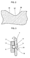
- Fig. 2 is an enlarged view of groove 16. Bottom 37 thereof has a curve having a larger radius than the radius of roller 6. A first slope 36 forms a larger angle than a second slope 35 does.
- roller 6 situated in angular groove 13 reacts the pressure force of spring 7, rolls in V-shaped groove 16, then runs up onto, e.g. slope 35, and comes off V-shaped groove 16.
- the torque limiter thus functions.
- the threshold value of transmittable torque can be selectively varied depending on the pressure force of spring 7 and the shape of V-shaped groove 16 onto which roller 6 runs up, i.e. an angle of slope 35.
- slope 36 requires greater threshold value of the transmittable torque than slope 35.
- Respective desirable torque in different rotating directions can be thus obtained by selecting the pressure force of spring 7 and a shape of asymmetric V-shaped groove.
- roller 6 comes off V-shaped groove 16 and idles.
- the torque on retainer 3 is thus not transmitted to sprocket 4, i.e. the torque transmission from the driver to the follower is discontinued.
- sprocket 4 i.e. the torque transmission from the driver to the follower is discontinued.
- the V-shaped groove is formed in sprocket 4.
- the V-shaped groove may be formed in retainer 3.
- grooves may be formed in both retainer 3 and sprocket 4 with portions of each groove having one or both of the side wall angles described above.
- spring 7 may be deleted if retainer 3 is made of a spring-like material.
- the second embodiment uses a different shape of V-shaped holding groove formed on sprocket 4 from that used in the first embodiment.
- an approximate V-shaped holding groove formed on sprocket 4 has following dimensions: depth: 1 mm, slope 17 of which slant angle ⁇ is 15°, slope 18 is curved with radius of 3 mm, and bottom face 19 lying between slopes 17 and 18.
- three V-shaped grooves 16 are formed radially with 120° intervals.
- three angular grooves 13 are formed radially at the places corresponding to V-shaped grooves 16.
- Grooves 13 have a depth of 4 mm and house respective cylindrical rollers 6 measuring 5.5 mm across rotatably.
- the other structures are the same as those of the first embodiment.
- rollers 6 situated in angular grooves 13 on retainer 3 react the pressure force of the belleville spring, roll in V-shaped grooves 16, run up onto, e.g. slope 17 and come off grooves 16. At this moment, the torque generated by motor 1 stops being transmitted from retainer 3 to sprocket 4.
- the torque limiter functions in this way.
- the threshold value of transmittable torque can be selectively varied depending on the pressure force of the belleville spring and the shape of V-shaped groove 16 onto which roller 6 runs up, i.e. an angle formed by slope 17.
- curved face 18 requires greater threshold value of the transmittable torque than slope 17. For instance, when slope 17 forms an angle of 15° and curved face 18 has a radius of 3 mm, curved face 18 requires three times torque for roller 6 to run up as much as roller 6 runs up slope 17.
- Respective desirable torque in different rotating directions can be thus obtained by selecting the pressure force of the spring and a shape of asymmetric V-shaped groove 16.
- the third embodiment uses a different shape of V-shaped groove formed on sprocket 24 from that used in the second embodiment.
- V-shaped holding grooves are formed in this manner: slopes 22 having a greater slant angle are formed radially on sprocket 24, and slopes 21 having a smaller slant angle are formed in parallel with slopes 22.
- Other structures remain the same as those of the second embodiment.
- Table 1 shows measured threshold values of transmittable torque, i.e. limit torque values, when the pressure force of the belleville spring, and the combination of slant angle ⁇ with curved face R are varied in embodiments 1 through 3.
- Curved face R 3mm 3 kgf 3.2 3.5 3.9 8.1 6 kgf 7.3 8.1 9.0 24.5 9 kgf 10.3 12.1 13.1 35.5
- the fourth embodiment differs from the embodiments 1 through 3 in the structure of approx. V-shaped grooves. As shown in Fig. 6, V-shaped holding grooves 29 and 30 having different slant angles are formed on both sides of sprocket 34 symmetrically. The rotating direction generates a difference between the values of limit torque, which has been proved in the embodiments 1 through 3, and this fact is also true in this fourth embodiment. Further, in this embodiment, the positional relation between slope 27 and curved face 28 can be reversed by turning over sprocket 34, so that the direction generating a difference of limit torque is reversed with ease.
- V-shaped grooves 29 and 30 are provided symmetrically both in shape and location; however, in location wise, they may be asymmetric.
- the retainer is coupled with the output shaft of motor via the sleeve; however, the tapped hole and the spline can be provided on the output shaft so that the output shaft can be directly connected with the retainer.
- a rotary body on the follower side is a sprocket; however, the rotary body can be a pulley that rotates a V belt or a timing belt.
- inner rotary body 43 is fixed by pin 49 on rotary shaft 41 that outputs torque of motor 40 having reduction gears as a driver.
- Outer rotary body 44 on a follower side has a sprocket on its outer circumference.
- Shaft 41 journals outer rotary body 44 outside the inner rotary body 43.
- An angular groove 45 is formed on outer body 44 to hold ball 46.
- Inner body 43 has an asymmetric V-shaped holding groove 42 on its outer face corresponding to angular groove 45. Holding groove 42 normally holds ball 46.
- Angular groove 45 houses ball 46 and coil spring 47 which urges ball 46. Screw 48 can adjust the pressure force loaded to ball 46.
- both the slopes of V-shaped groove 42 have different angles with regard to respective tangent lines of inner body 43, i.e. angle ⁇ is greater than angle ⁇ .
- inner rotary body 43 has three V-shaped grooves formed radially with 120° intervals, and the grooves have the following dimensions: depth: 1 mm, a first slope of which slant angle is 7.5°, a second slope is curved with radius of 2 mm.
- Outer rotary body 44 urges inner body 44 via ball 46 using the pressure force of spring 47. This construction allows inner body 43 to rotate together with outer body 44. When a torque over the pressure force of spring 47 is loaded onto outer body 44, ball 46 can move radially and outwardly.
- rotation of motor 40 entails inner rotary body 43 fixed by pin 49 on shaft 41 to rotate. Since ball 46 in angular groove 45 is urged by spring 47 to V-shaped holding groove 42 formed on outer face of inner rotary body 43, the rotation of inner body 43 naturally entails outer body 44 to rotate. As a result, the torque from the driver is transmitted to the follower.
- the torque loaded to outer body 44 exceeds a given threshold value
- ball 46 reacts the pressure force of spring 47 and rolls in V-shaped groove 42 to run up onto the slope. Ball 46 comes off the groove 42, then the torque transmission is discontinued, i.e. the torque limiter functions.
- the given threshold value is selectively determined depending on the pressure force of spring 47 and a shape of V-groove, namely, a slope angle and a radius of curved face.
- Different threshold values of torque can be thus set responsive to the rotating directions of outer rotary body 44 on the follower side.
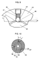
- the sixth embodiment differs from the embodiments 5 in the structure of an angular groove. As shown in Fig. 10, angular grooves 55 are formed having angle ⁇ with regard to respective radial lines extending from the shaft center. This structure allows the limit torque to take different values responsive to rotating directions.
- Outer rotary body 54 on the follower side is journaled by the rotary shaft and disposed outside the inner rotary body 53.
- An angular groove 55 is formed on outer body 54 to house ball 56.
- Inner body 53 has an asymmetric V-shaped groove 52 on its outer face corresponding to angular groove 55. Groove 52 normally holds ball 56.
- Angular groove 55 houses ball 56 and coil spring 57 that urges ball 56. Screw 58 can adjust the pressure force loaded to ball 56.
- Angular groove 55 is provided to form angle ⁇ with regard to a line radially extending from the rotary center.
- the rotary body on the follower side has the sprocket; however, instead of the sprocket the rotary body may have a pulley for a V-belt or a timing belt, or a shaft coupler for power transmission.
- sleeve 65 is fixed by pin 68 on output shaft 62 of motor 61 (driver) with reduction gears.
- Retainer 63 which is a rotary body of the driver side
- sprocket 64 which is a rotary body on the follower side are mounted on a cylindrical section 72 of sleeve 65.
- Angular groove 73 is formed on retainer 63, and groove 73 receives roller 66.
- Belleville spring 67 having elasticity is disposed between pressure nuts 69 and retainer 63. Nuts 69 are screwed onto threaded section 71 on sleeve 65, thereby spring 67 generates pressure force. The pressure force presses retainer 63 to urge roller 66 against sprocket 64. Then sprocket 64 is urged to flange 75 of sleeve 65.
- Retainer 63 in a shape of hollow disc is held in a rotating direction of sleeve 65 by inserting key 70 into spline 74, so that retainer 63 rotates together with sleeve 65.
- Retainer 63 is also urged by belleville spring 67 in axial direction of the output shaft of motor 61. Retainer 63 reacts the pressure force of spring 67 and is able to move in axial direction toward motor 61 when spring 67 is imposed by the force over a given value.
- Sprocket 64 has an approximate and asymmetric V-shaped groove 76 on its side face in, and groove 76 normally holds roller 66 and faces to angular groove 73 of retainer 63.
- Switch 77 is mounted to motor 61 to be adjacent to retainer 63 so that switch 77 can work when retainer 63 moves axially by the excessive torque over a given threshold value loaded to sprocket 64.
- Switch 77 is a "NC" (normally closed) switch, and can be made of piezoelectric elements.
- roller 66 situated in angular groove 73 reacts the pressure force of spring 67, rolls in V-shaped groove 76, then runs up onto a slope, and comes off V-shaped groove 76.
- the torque limiter functions in this way.
- the threshold value of transmittable torque can be selectively varied depending on the pressure force of spring 67 and the shape of V-shaped groove onto which roller 66 runs up, i.e. an angle of the slope.
- Switch 77 is closely placed to retainer 63 with clearance of 0.5 - 1 mm in axial direction on the condition that the torque limiter does not function. When the torque limiter functions, retainer 63 moves axially and push switch 77 to open.
- a breaking circuit including switch 77 is described with reference to Fig. 12.
- the breaking circuit has the following construction.
- a first end of motor coil 201 for spinning the motor clockwise is connected to a first end of motor coil 202 for spinning the motor counter clockwise.
- the contact point of these coils is connected to a first end of commercial power supply 200.
- coil 203 of relay RY1 Between the contact point and a second end of commercial power supply 200, coil 203 of relay RY1, NO switch 214 (normally open) for spinning the motor clockwise, NC switch 219 for breaking current to stop the motor at an emergency, and NC switch 220 corresponding to switch 77 shown in Fig. 11, are connected in series.
- coil 204 of relay RY2 NO switch 215 for counter clockwise spin, stop switch 219, and switch 220 are connected in series.
- Relay RY1 comprises NO switches 211, 213 and NC switch 218.
- Powering coil 203 activates switches 211, 213 and 218.
- Relay RY2 comprises NO switches 212, 216 and NC switch 217.
- Powering coil 204 activates those switches.
- a second end of motor coil 201 is coupled to the second end of commercial power supply 200 via switch 211, and a second end of motor coil 202 is coupled to the second end of commercial power supply 200 via switch 212. Between both the terminals of switch 214, switches 213 and 217 are connected in series. Between both the terminals of switch 215, switches 216 and 218 are connected in series.
- a capacitor is connected between the second end of coil 201 and the second end of coil 202.
- NO switch 216 of relay RY2 closes, and NC switch 218 remains closed because it is not activated.
- the voltage of commercial power supply 200 is thus applied to relay RY2, and current keeps running through coil 204, thereby constructing a self-holding circuit of RY2.
- NO switch 212 of relay RY2 closes, and motor coil 202 is powered, so that the motor spins counter clockwise.
- NC switch 217 of relay RY2 opens so that the voltage of power supply 200 is not applied to relay RY1.
- NC switch 220 opens, thereby breaking the self-holding circuit of relay RY1 and opening NO switch 211.
- current to motor coil 201 is cut off and the motor stops.
- the torque limiter functions and the retainer moves axially to push switch 220.
- the current to motor coil 202 is cut off in the same manner, and the motor stops.
- Pressing stop-switch 219 also breaks the self-holding circuits of relays RY1 and RY2, thereby opening switches 211 and 212. As a result, the current to the motor is cut off, and the motor stops. When restoring the motor, press switch 214 or 215 to work either one of self-holding circuit of relay RY1 or RY2. Then the motor spins clockwise or counter clockwise accordingly.
- threaded section 82 is formed on output shaft 92 of motor 81 (driver) having reduction gears.
- Pressure nut 89 is screwed into threaded section 82.
- Belleville spring 87 an elastic body, is disposed between pressure nut 89 and retainer 83 which is a rotary body of the driver side.
- Sprocket 84 which is a rotary body on the follower side is urged by the pressure force of spring 87 to flange 99 via retainer 83 and roller 86 housed in the angular groove on retainer 83.
- Retainer 83 in a shape of hollow disc is held in a rotating direction of shaft 92 by inserting key 90 into a spline, so that retainer 83 rotates together with shaft 92.
- Retainer 83 is also urged by belleville spring 87 in axial direction.
- Retainer 83 reacts the pressure force of spring 87 and is able to move in axial direction toward motor 81 when spring 87 is loaded by the force over a given value.
- Sprocket 84 has an approximate and asymmetric V-shaped groove on its side face.
- Switch 97 is mounted to motor 81 to be adjacent to retainer 83 so that switch 97 can work when retainer 83 moves axially by the excessive torque over a given threshold value loaded to sprocket 84.
- Switch 97 is a "NC" (normally closed) switch. and can be made of piezoelectric elements. Particularly in this eighth embodiment, protrusions 98 are formed on octant positions of retainer 83 so that protrusion 98 can contact switch 97. This arrangement allows switch 97 to open/close instantaneously free from errors.
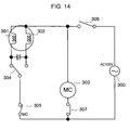
- the ninth embodiment handles a torque transmitter including another breaking circuit shown in Fig. 14.
- a first end of motor coil 301 which spins the motor clockwise is connected to a first end of motor coil 302 which spins the motor counter clockwise.
- the contact point of these motor coils is coupled to a first end of commercial power supply 300 via motor-starter-switch 306.
- Respective second ends of motor coils 301 and 302 are coupled to a second end of commercial power supply 300 via switch 304 which switches a rotating direction, and NC (normally closed) switch 305 that is activated when breaker coil 303 is powered.
- switch 304 which switches a rotating direction
- NC normally closed switch 305
- breaker coil 303 and NO (normaly open) switch 307 are connected in series.
- Switch 307 is disposed adjacently to a retainer and is activated when a rotary body on a driver side is moved axially with limit torque.
- a capacitor is connected across the respective second ends of motor coils 301 and 302.
- the tenth embodiment handles a torque transmitter including still another breaking circuit shown in Fig. 15.
- a first end of motor coil 311 which spins the motor clockwise is connected to a first end of motor coil 312 which spins the motor counter clockwise.
- the contact point of these motor coils is coupled to a first end of commercial power supply 310 via motor-starter-switch 317.
- Respective second ends of motor coils 311 and 312 are coupled to a second end of commercial power supply 310 via switch 315 which switches a rotating direction and NC (normally closed) switch 316 that is activated when breaker coil 313 is powered.
- a stator of the motor has supplemental coils, and a power generator 314 is formed which generates voltages on the supplemental coils by spinning a rotor of the motor.
- a first end of power generator 314 is coupled to a second end thereof via breaker coil 313 and NO (normally open) switch 318 that is activated when the rotary body on a driver side moves axially with limit torque.
- a capacitor is connected across the respective second ends of motor coils 311 and 312.
- switch 315 is coupled to motor coil 311.
- the torque limiter does not function yet, and NC switch 316 is closed.
- close switch 317 and apply a voltage of power supply 310 to motor coil 311.
- the motor spins clockwise.
- the power generator 314 generates power responsive to the spin; however, NO switch 318 is not activated yet and remains open, thus breaker coil 313 is not powered.
- the 11th embodiment handles a torque limiter built in a gear section of reduction gears.
- Shaft 111 on which gears are formed, outputs the torque generated by motor 100 into gear section 115, and the torque is transmitted via a plurality of gears to inner rotary body 112 having gears on its outer rim.
- Rotatable shaft 101 extends through the center of inner rotary body 112 and is fixed in body 112.
- Outer rotary body 113 is disposed outside the inner body 112.
- an angular groove is formed on outer rotary body 113.
- the groove houses ball 106 and spring 107 that urges the ball. Pressure force of spring 107 can be varied by adjusting the fastening force of screw 108.
- Asymmetric V-shaped groove 109 is formed on the outer rim of inner body 112 so that groove 109 can face the angular groove.
- the torque traveled from inner body 112 is transmitted to outer body 113 via ball 106 urged by spring 107.
- the torque is further transmitted to output gear 114 via a pinion gear provided at the end of outer body 113.
- the torque is finally transmitted to the follower side via output shaft 102 fixed to gear 114 and sprocket 104 fixed to shaft 102.
- the 12th embodiment handles an improvement of the first embodiment. A problem still remaining in the first embodiment is discussed hereinafter first.
- the construction of the torque limiter used in the first exemplary embodiment is as follows:
- the angular groove formed on the rotary body of the driver side houses the roller, which engages with the V-shaped groove formed on the rotary body of the follower side.
- the rotary body on the driver side reacts the pressure force of elastic body and moves axially, and then the roller comes off the V-shaped groove.
- torque transmission is discontinued.
- the roller since the roller is housed by the angular groove provided on the rotary body of driver side, the roller is subjected to both the pressure force from the elastic body and the force driving the follower. The roller thus won't roll but just revolves together with the driver and follower sides by friction during the torque transmission. Away of usage may shorten the service life, or make the limit-torque-value unstable.
- the torque limiter used in the first embodiment When the torque limiter used in the first embodiment is employed in an electric shutter, it can be used for detecting an obstacle because it does not function so frequently in such an application; however, it will not endure frequent use because of its service life.
- the twelfth embodiment addresses this problem, and aims to provide a torque limiter having a long service life and a more stable limit torque value than that used in the first embodiment.
- Fig. 17 is a cross sectional view of essential part of a torque limiter in accordance with the twelfth embodiment.
- spline 514 is formed on output shaft 502 of motor 501 (driver) having reduction gears, and key 510 is inserted into spline 514 so that rotary body 503 on the driver's side is fixed.
- Hole 513 is formed on rotary body 503, and hole 513 holds steel ball 506 as a roller.
- Steel ball 506 is sandwiched by rolling panel 520 and rotary body 504 on a follower side.
- Rotary body 504 is a hollow disc and has asymmetric protrusions 516 which hold steel balls 506. Protrusions 516 has different angles formed by its respective slopes.
- Rolling panel 520 urges steel ball 506 with spring 507 that is pressed by fastening pressure nut 509.
- Rotary body 504 on the follower side is fixed axially by collar 515, snap ring 517 and screw 518.
- the pressure force of rolling panel 520 is transmitted to rotary body 504 via steel ball 506.
- Spring 507 is made of a plurality of wave washers, and an elastic body pressing the rolling panel 520 employs spring 507 and flat washers 511, where wave washers and flat washers are alternately arranged.
- the elastic body can be a single wave washer or a coil spring instead of combination of wave washers and flat washers.
- Fig. 18A is a plan view of rotary body 504 on the follower side used in the twelfth embodiment.
- Fig. 18B is a front view of the same, and
- Fig. 18C is a right side view of the same.
- Fig. 18D is an enlarged cross section of protrusion 516 provided on rotary body 504.
- rotary body 504 has protrusions 516 as a holding section, which comprise ridge 539, slope 540 on the left hand of ridge 539, and slope 541 on the right hand of ridge 539. Slope 540 forms angle ⁇ and slope 541 forms angle ⁇ , angle ⁇ is greater than angle ⁇ .
- Fig. 17 first, rotate output shaft 502 of motor 501, then the torque is transmitted to rotary body 503 on the driver side via key 510, and rotary body 503 rotates. Steel ball 506 held in hole 513 of rotary body 503 is urged by spring 507, so that it engages with protrusion 516 formed on a side face of rotary body 504 of the follower side. The torque is thus transmitted to the follower side.
- Rotary body 503 of the driver side rotates together with rotary body 504 of the follower side.
- steel ball 506 in hole 513 reacts the pressure force of spring 507 and rolls around protrusion 516. For instance, steel ball 506 runs up onto slope 540 and comes off ridge 539. At this moment, the torque generated by motor 501 is discontinued being transmitted from rotary body 503 on the driver side to rotary body 504 on the follower side. In other words, the torque transmission is stopped.
- the torque limiter functions in this way.
- the transmittable limit-torque-value can be selectively determined depending on the pressure force of spring 507 and a shape of protrusion 516, i.e. the angle formed by slope 540.
- slope 541 When motor 501 spins the other way around, excessive torque to rotary body 504 on the follower side allows steel body 506 to run up slope 541 and come off ridge 539. Since the angle formed by slope 541 is greater than that by slope 540, slope 541 requires greater torque for steel ball 506 to come off ridge 539 than slope 540 does. In other words, slope 541 needs a greater limit torque value.
- Respective desirable torque in different rotating directions can be thus obtained by selecting the pressure force of the spring 507 and a shape of protrusion 516, i.e. angles of both the slopes.
- the twelfth embodiment proves that different limit torque values depending on rotating directions can be obtained in a simple construction of the torque limiter, which assures a long service life and stable torque.
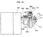
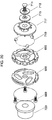
- Fig. 19 is a cross sectional view illustrating the engagement of a rotary body mounted on a driver side, a roller and a rotary body mounted on a follower side in accordance with the 13th embodiment
- Fig. 20 is an exploded perspective view illustrating the engagement of the same.
- spline 614 is formed on output shaft 602 of motor 601 (driver) having reduction gears, and key 610 is inserted into spline 614 so that rotary body 603 on the driver side is fixed to output shaft 602.
- Rotary body 603 integrates position-adjustment-holder 668 with screw 669. Long holes are provided on both holder 668 and rotary body 603, and steel ball 719 is held in the overlapping section of respective long holes. Steel ball 719 is sandwiched by rolling panel 729 and rotary body 717 of the follower side.
- Rotary body 717 is a hollow disc and has asymmetric protrusions as holding sections at the places corresponding to steel ball 719.
- Rolling board 729 urges steel ball 719 with spring 607 that is pressed by fastening pressure nut 609.
- Rotary body 717 on the follower side is fixed axially by collar 715, snap ring 713 and screw 711. The pressure force of rolling panel 729 is transmitted to rotary body 717 via steel ball 719.
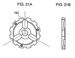
- rotary body 603 As shown in Fig. 21A, three long holes 782 for holding ball 719 are provided on rotary body 603 radially at 120° intervals. As shown in Fig. 22A, long holes 786 are provided on holder 668 forming angle ⁇ with regard to radial lines from the center. Long holes 787 through which screws 669 extend are also provided on holder 668. Rotary body 603 and holder 668 are laid up on top another after respective angles in the rotating direction are adjusted at the given positions. Then, rotary body 603 and holder 668 are integrated with screws 669.
- rotary body 603 and holder 668 are combined concentrically, and the overlapping sections of long holes 782 and 786 hold steel balls 719.
- long hole 786 When long hole 786 is at position 873, the ball is situated at position 853, i.e. middle of long hole 782. When long hole 786 is at position 875, the ball is at position 855, i.e. inner most of long hole 782 (ref. Fig. 23B).
- a relative positional relation between rotary body 603 and holder 668 in the rotating direction can be arbitrary changed, and the ball position can be changed responsive to the relative positional relation.
- this structure allows the radius between the ball center and the center of rotary body 603 to vary from R L shown in Fig. 23C to R S shown in Fig. 23B by changing the position of holder 668 in rotating direction with regard to body 603. Since radius R L is greater than radius R S , the torque transmitted to rotary body 717 on the follower side from output shaft 602 is greater in the case of Fig. 23C than Fig. 23B, provided the output torque is the same. In the meantime, the pressure force of spring 607 and the shape of protrusions provided on rotary body 717 stay the same both in Figs. 23B and 23C. The ball needs a certain power to climb over the protrusion, and the power needed is constant for every protrusion. In the case of Fig. 23C, limit torque is set based on greater transmitted torque, therefore this case can obtain greater limit torque as a torque limiter.
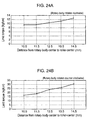
- Fig. 24A illustrates a relation between the limit torque and the radius from the center of rotary body 603 to the ball center, i.e. R L and R S when rotary body 717 rotates clockwise. As this graph tells, the torque limiter has greater limit-torque at a longer radius.
- Fig. 24B shows characteristics when rotary body 717 rotates counter clockwise. In this case also, the torque limiter has greater limit-torque at a longer radius.
- the 13th embodiment thus proves that the limit torque can be changed under the constant pressure force of spring 607. Since both the slopes of the protrusion on rotary body 717 form different angles, respective desirable torque in different rotating directions can be obtained. As comparing Figs. 24A with Fig. 24B illustrates this matter, a limit-torque-value varies responsive to the shape differences of protrusion on rotary body 717.
- the driver of the present invention is not limited to a motor with reduction gears, but other types of motors or a driving device other than the motors can produce the same result.
- the application of the torque limiter of the present invention is not limited to an electric shutter, but the torque limiter can be used in other apparatuses, and thus produces great industrial advantages.
Landscapes
- Engineering & Computer Science (AREA)
- General Engineering & Computer Science (AREA)
- Mechanical Engineering (AREA)
- One-Way And Automatic Clutches, And Combinations Of Different Clutches (AREA)
- Transmission Devices (AREA)
Applications Claiming Priority (6)
| Application Number | Priority Date | Filing Date | Title |
|---|---|---|---|
| JP20892698 | 1998-07-24 | ||
| JP20892698 | 1998-07-24 | ||
| JP22395998 | 1998-08-07 | ||
| JP22395998 | 1998-08-07 | ||
| JP31586198 | 1998-11-06 | ||
| JP31586198 | 1998-11-06 |
Publications (1)
| Publication Number | Publication Date |
|---|---|
| EP0974765A2 true EP0974765A2 (de) | 2000-01-26 |
Family
ID=27328943
Family Applications (1)
| Application Number | Title | Priority Date | Filing Date |
|---|---|---|---|
| EP99114334A Withdrawn EP0974765A2 (de) | 1998-07-24 | 1999-07-21 | Drehmomentübertragungseinrichtung mit Drehmomentbegrenzer |
Country Status (2)
| Country | Link |
|---|---|
| US (1) | US6302798B1 (de) |
| EP (1) | EP0974765A2 (de) |
Cited By (4)
| Publication number | Priority date | Publication date | Assignee | Title |
|---|---|---|---|---|
| FR2972775A1 (fr) * | 2011-03-18 | 2012-09-21 | Thales Sa | Accouplement a glissement bidirectionnel presentant un couple de glissement different dans chaque sens de rotation |
| CN105179917A (zh) * | 2015-09-11 | 2015-12-23 | 湖州乐而达纺织有限公司 | 一种纺织机用防夹装置 |
| CN107588946A (zh) * | 2017-08-22 | 2018-01-16 | 西安交通大学 | 一种基于阿基米德螺旋线的动态加载装置 |
| CN113685456A (zh) * | 2020-05-19 | 2021-11-23 | 株式会社日立大厦系统 | 机器人的动力传递机构以及使用该动力传递机构的机器人 |
Families Citing this family (14)
| Publication number | Priority date | Publication date | Assignee | Title |
|---|---|---|---|---|
| US20080135356A1 (en) * | 2006-12-06 | 2008-06-12 | Yungh-Siang Lin | Transmission motor structure |
| US8011063B2 (en) * | 2007-02-05 | 2011-09-06 | Nilfisk-Advance A/S | Overload clutch for rotating agitation member in cleaning machine |
| DE202011003309U1 (de) * | 2011-02-28 | 2011-06-09 | Magnetic Autocontrol GmbH, 79650 | Durchgangssperre |
| US10433842B2 (en) | 2017-04-07 | 2019-10-08 | Lexington Medical, Inc. | Surgical handle assembly |
| US10912560B2 (en) | 2017-06-23 | 2021-02-09 | Lexington Medical, Inc. | Surgical reloadable cartridge assembly |
| US11376003B2 (en) * | 2018-07-05 | 2022-07-05 | Lexington Medical, Inc. | Surgical handle articulation assembly |
| US10856871B2 (en) | 2019-01-16 | 2020-12-08 | Lexington Medical, Inc. | Advancing a toothed rack of a surgical handle assembly |
| US11298131B2 (en) | 2020-01-15 | 2022-04-12 | Lexington Medical, Inc. | Multidirectional apparatus |
| US11116501B1 (en) | 2020-04-10 | 2021-09-14 | Lexington Medical, Inc. | Surgical handle articulation assemblies |
| US11864757B2 (en) | 2021-01-15 | 2024-01-09 | Lexington, Medical, Inc. | Reloadable cartridge assembly |
| US11622764B2 (en) | 2021-04-27 | 2023-04-11 | Lexington Medical, Inc. | Surgical handle assembly |
| US12343009B2 (en) | 2021-06-07 | 2025-07-01 | Lexington Medical, Inc. | Motorized surgical handle assembly |
| WO2023034616A1 (en) | 2021-09-03 | 2023-03-09 | Lexington Medical, Inc. | Staple line surgical buttress |
| US12508020B2 (en) | 2022-02-11 | 2025-12-30 | Lexington Medical, Inc. | Blade assembly for a surgical reloadable cartridge assembly |
Family Cites Families (12)
| Publication number | Priority date | Publication date | Assignee | Title |
|---|---|---|---|---|
| US2490172A (en) * | 1945-04-21 | 1949-12-06 | Swahnberg Gunnar | Bidirectional overload clutch |
| US2802354A (en) * | 1954-12-06 | 1957-08-13 | Gen Motors Corp | Coupling |
| US2969132A (en) * | 1955-12-09 | 1961-01-24 | Harold H Stewart | Torque limiting devices |
| GB1049525A (en) * | 1962-06-30 | 1966-11-30 | Fisher & Ludlow Ltd | A new or improved overload clutch or torque limiting device |
| US3786693A (en) * | 1972-05-25 | 1974-01-22 | Teletype Corp | Detent mechanism for releasably securing relatively rotatable members |
| US3942337A (en) * | 1974-09-16 | 1976-03-09 | Industrial Analytics Inc. | Torque limiting device |
| JPS5521893A (en) | 1978-07-28 | 1980-02-16 | Siemens Ag | Device for alternatively twisting cable cores in leftthanded and rightthanded lays |
| US4263996A (en) * | 1979-10-01 | 1981-04-28 | Harnischfeger Corporation | Readily resettable torque-limiting coupling device |
| JPS5848860A (ja) * | 1981-09-18 | 1983-03-22 | Toa Medical Electronics Co Ltd | 自動分析測定装置における衝撃緩和機構 |
| US4792321A (en) | 1987-06-22 | 1988-12-20 | Sundstrand Corporation | Radial ball torque limiter |
| DE4121892A1 (de) * | 1991-07-02 | 1993-01-14 | Airbus Gmbh | Rutschkupplung |
| JP3658804B2 (ja) * | 1995-07-17 | 2005-06-08 | 日本精工株式会社 | 回転運動用ダンパ装置 |
-
1999
- 1999-07-21 EP EP99114334A patent/EP0974765A2/de not_active Withdrawn
- 1999-07-23 US US09/359,508 patent/US6302798B1/en not_active Expired - Fee Related
Cited By (5)
| Publication number | Priority date | Publication date | Assignee | Title |
|---|---|---|---|---|
| FR2972775A1 (fr) * | 2011-03-18 | 2012-09-21 | Thales Sa | Accouplement a glissement bidirectionnel presentant un couple de glissement different dans chaque sens de rotation |
| CN105179917A (zh) * | 2015-09-11 | 2015-12-23 | 湖州乐而达纺织有限公司 | 一种纺织机用防夹装置 |
| CN105179917B (zh) * | 2015-09-11 | 2018-05-11 | 湖州乐而达纺织有限公司 | 一种纺织机用防夹装置 |
| CN107588946A (zh) * | 2017-08-22 | 2018-01-16 | 西安交通大学 | 一种基于阿基米德螺旋线的动态加载装置 |
| CN113685456A (zh) * | 2020-05-19 | 2021-11-23 | 株式会社日立大厦系统 | 机器人的动力传递机构以及使用该动力传递机构的机器人 |
Also Published As
| Publication number | Publication date |
|---|---|
| US6302798B1 (en) | 2001-10-16 |
Similar Documents
| Publication | Publication Date | Title |
|---|---|---|
| US6302798B1 (en) | Torque reducer and torque transmitter including the same | |
| US5419745A (en) | Torque release mechanism for an electronically powered tool | |
| US4263996A (en) | Readily resettable torque-limiting coupling device | |
| EP1970165A1 (de) | Motorbetriebenes Drehwerkzeug mit einem ersten und einem zweiten Geschwindigkeitsmodus | |
| US5234089A (en) | Torque limiter | |
| CA1076984A (en) | Limited torque drive roller | |
| JP2022537982A (ja) | 電動工具及び電動工具用トルク応答型ギアユニット | |
| US4593800A (en) | Torque release drive connector | |
| US4693349A (en) | Torque limiting apparatus | |
| EP0006082B1 (de) | Vorrichtung zum Umwandeln einer drehenden in eine geradlinige Bewegung | |
| US3435695A (en) | Shear pin safety hub | |
| PT860579E (pt) | Accionamento de correia de carga | |
| JP2000199530A (ja) | トルクリミッタ及びトルク伝達装置 | |
| JP2759610B2 (ja) | モータ内蔵ローラ及びクラッチ装置 | |
| WO1994020771A1 (en) | Transmission device | |
| JPS6125937B2 (de) | ||
| JPH11873A (ja) | ボルトナット締付け機 | |
| KR820001049B1 (ko) | 전동패스닝(fastening)공구 | |
| CA2270262A1 (en) | Scroll-type compressor | |
| WO2003048609A1 (en) | A lead screw and nut assembly device | |
| US12551999B2 (en) | Overload clutch for a hand-held power tool | |
| JP2001271897A (ja) | 摩擦ローラ式変速機 | |
| RU2215209C1 (ru) | Храповой механизм свободного хода | |
| CN110848284A (zh) | 带反向输入阻断离合器的电动机及反向输入阻断离合器 | |
| JPH0525827Y2 (de) |
Legal Events
| Date | Code | Title | Description |
|---|---|---|---|
| PUAI | Public reference made under article 153(3) epc to a published international application that has entered the european phase |
Free format text: ORIGINAL CODE: 0009012 |
|
| AK | Designated contracting states |
Kind code of ref document: A2 Designated state(s): AT BE CH CY DE DK ES FI FR GB GR IE IT LI LU MC NL PT SE |
|
| AX | Request for extension of the european patent |
Free format text: AL;LT;LV;MK;RO;SI |
|
| STAA | Information on the status of an ep patent application or granted ep patent |
Free format text: STATUS: THE APPLICATION IS DEEMED TO BE WITHDRAWN |
|
| 18D | Application deemed to be withdrawn |
Effective date: 20060201 |