EP0974877A2 - Appareil de formation d'images - Google Patents
Appareil de formation d'images Download PDFInfo
- Publication number
- EP0974877A2 EP0974877A2 EP99114350A EP99114350A EP0974877A2 EP 0974877 A2 EP0974877 A2 EP 0974877A2 EP 99114350 A EP99114350 A EP 99114350A EP 99114350 A EP99114350 A EP 99114350A EP 0974877 A2 EP0974877 A2 EP 0974877A2
- Authority
- EP
- European Patent Office
- Prior art keywords
- transfer
- intermediate transfer
- roller
- voltage
- image
- Prior art date
- Legal status (The legal status is an assumption and is not a legal conclusion. Google has not performed a legal analysis and makes no representation as to the accuracy of the status listed.)
- Withdrawn
Links
- 238000012546 transfer Methods 0.000 claims abstract description 344
- 230000002093 peripheral effect Effects 0.000 claims abstract description 11
- 239000002131 composite material Substances 0.000 claims abstract description 6
- 238000012545 processing Methods 0.000 claims description 10
- 239000010410 layer Substances 0.000 description 49
- 239000002245 particle Substances 0.000 description 16
- 238000004140 cleaning Methods 0.000 description 10
- 239000000654 additive Substances 0.000 description 9
- 230000000996 additive effect Effects 0.000 description 9
- 238000011161 development Methods 0.000 description 6
- 238000000034 method Methods 0.000 description 6
- 229920005989 resin Polymers 0.000 description 6
- 239000011347 resin Substances 0.000 description 6
- 229910052799 carbon Inorganic materials 0.000 description 4
- 239000003795 chemical substances by application Substances 0.000 description 4
- 238000000926 separation method Methods 0.000 description 4
- YCKRFDGAMUMZLT-UHFFFAOYSA-N Fluorine atom Chemical compound [F] YCKRFDGAMUMZLT-UHFFFAOYSA-N 0.000 description 3
- 239000006185 dispersion Substances 0.000 description 3
- 230000005684 electric field Effects 0.000 description 3
- 229910052731 fluorine Inorganic materials 0.000 description 3
- 239000011737 fluorine Substances 0.000 description 3
- 238000002156 mixing Methods 0.000 description 3
- 229920003002 synthetic resin Polymers 0.000 description 3
- 239000000057 synthetic resin Substances 0.000 description 3
- OKTJSMMVPCPJKN-UHFFFAOYSA-N Carbon Chemical compound [C] OKTJSMMVPCPJKN-UHFFFAOYSA-N 0.000 description 2
- JOYRKODLDBILNP-UHFFFAOYSA-N Ethyl urethane Chemical compound CCOC(N)=O JOYRKODLDBILNP-UHFFFAOYSA-N 0.000 description 2
- VYPSYNLAJGMNEJ-UHFFFAOYSA-N Silicium dioxide Chemical compound O=[Si]=O VYPSYNLAJGMNEJ-UHFFFAOYSA-N 0.000 description 2
- 239000006258 conductive agent Substances 0.000 description 2
- 238000010586 diagram Methods 0.000 description 2
- 230000008030 elimination Effects 0.000 description 2
- 238000003379 elimination reaction Methods 0.000 description 2
- 239000003973 paint Substances 0.000 description 2
- 230000003746 surface roughness Effects 0.000 description 2
- XOLBLPGZBRYERU-UHFFFAOYSA-N tin dioxide Chemical compound O=[Sn]=O XOLBLPGZBRYERU-UHFFFAOYSA-N 0.000 description 2
- 238000005054 agglomeration Methods 0.000 description 1
- 230000002776 aggregation Effects 0.000 description 1
- 238000013459 approach Methods 0.000 description 1
- 239000011248 coating agent Substances 0.000 description 1
- 238000000576 coating method Methods 0.000 description 1
- 239000003086 colorant Substances 0.000 description 1
- 230000006866 deterioration Effects 0.000 description 1
- 238000001035 drying Methods 0.000 description 1
- 238000001704 evaporation Methods 0.000 description 1
- 230000008020 evaporation Effects 0.000 description 1
- 239000000463 material Substances 0.000 description 1
- 239000000203 mixture Substances 0.000 description 1
- 239000000049 pigment Substances 0.000 description 1
- 238000003825 pressing Methods 0.000 description 1
- 230000000717 retained effect Effects 0.000 description 1
- 238000007790 scraping Methods 0.000 description 1
- 239000000377 silicon dioxide Substances 0.000 description 1
- 239000002356 single layer Substances 0.000 description 1
- 239000002904 solvent Substances 0.000 description 1
- 238000012421 spiking Methods 0.000 description 1
- 238000009827 uniform distribution Methods 0.000 description 1
- 238000011144 upstream manufacturing Methods 0.000 description 1
- 238000003466 welding Methods 0.000 description 1
Images


Classifications
-
- G—PHYSICS
- G03—PHOTOGRAPHY; CINEMATOGRAPHY; ANALOGOUS TECHNIQUES USING WAVES OTHER THAN OPTICAL WAVES; ELECTROGRAPHY; HOLOGRAPHY
- G03G—ELECTROGRAPHY; ELECTROPHOTOGRAPHY; MAGNETOGRAPHY
- G03G15/00—Apparatus for electrographic processes using a charge pattern
- G03G15/14—Apparatus for electrographic processes using a charge pattern for transferring a pattern to a second base
- G03G15/16—Apparatus for electrographic processes using a charge pattern for transferring a pattern to a second base of a toner pattern, e.g. a powder pattern, e.g. magnetic transfer
- G03G15/1605—Apparatus for electrographic processes using a charge pattern for transferring a pattern to a second base of a toner pattern, e.g. a powder pattern, e.g. magnetic transfer using at least one intermediate support
- G03G15/162—Apparatus for electrographic processes using a charge pattern for transferring a pattern to a second base of a toner pattern, e.g. a powder pattern, e.g. magnetic transfer using at least one intermediate support details of the the intermediate support, e.g. chemical composition
-
- G—PHYSICS
- G03—PHOTOGRAPHY; CINEMATOGRAPHY; ANALOGOUS TECHNIQUES USING WAVES OTHER THAN OPTICAL WAVES; ELECTROGRAPHY; HOLOGRAPHY
- G03G—ELECTROGRAPHY; ELECTROPHOTOGRAPHY; MAGNETOGRAPHY
- G03G2215/00—Apparatus for electrophotographic processes
- G03G2215/01—Apparatus for electrophotographic processes for producing multicoloured copies
- G03G2215/0167—Apparatus for electrophotographic processes for producing multicoloured copies single electrographic recording member
- G03G2215/0174—Apparatus for electrophotographic processes for producing multicoloured copies single electrographic recording member plural rotations of recording member to produce multicoloured copy
Definitions
- the present invention relates to an image forming apparatus, such as a printer, a facsimile or a copier, that forms an image using electrophotography.
- a photosensitive member which serves as a latent image bearing unit, having a photosensitive layer on an external surface
- charging means for uniformly electrifying the external surface of the photosensitive member
- exposure means for selectively exposing the external surface that is uniformly charged by the charging means and for forming an electrostatic latent image on the external surface
- developing means for applying charged toner
- a well known transfer device for transferring the toner image developed on the photosensitive member to a recording medium, such as paper is one that includes an intermediate transfer member to which the toner image formed on the photosensitive member is transferred (first transfer), and from which the toner image is transferred to a recording medium (second transfer).
- Fig. 4A is a schematic perspective view and Fig. 4B is a cross-sectional view taken along line b-b in Fig. 4A.
- a photosensitive member 1 formed on a photosensitive member 1 is a conductive layer 1a and a photosensitive layer 1b.
- the conductive layer 1a is grounded.
- An intermediate transfer member 2 is constituted by a dielectric member (middle resistance layer) having a resistance of, for example, 10 7 to 10 14 ⁇ cm.
- the intermediate transfer member 2 can be fabricated by mixing conductive carbon with synthetic resin.
- the intermediate transfer member 2 contacts the photosensitive member 1, at least during the image forming process, with contact point T1 serving as the first transfer point.
- contact point T1 serving as the first transfer point.
- a first transfer roller 3 which is located inside the intermediate transfer member 2, applies a first transfer voltage to an intermediate transfer member 2.
- a second transfer roller 4, for applying a second transfer voltage, is pressed against the intermediate transfer member 2, and the point at which pressure is applied serves as a second transfer point T2.
- a backup roller 5 is located inside the intermediate transfer member 2.
- the photosensitive member 1 and the intermediate transfer member 2 are rotated, the photosensitive layer 1b of the photosensitive member 1 is uniformly electrified by charging means (not shown), and the photosensitive member is selectively exposed by exposure means (not shown) to form an electronic latent image.
- a developing agent, toner is applied to the electrostatic latent image by developing means (nor shown) and a visible image (a toner image) is formed.
- the toner image is transferred to the intermediate transfer member 2, and at the second transfer point T2, the toner image is transferred to a recording medium, such as paper, that is fed to the second transfer point T2.
- a recording medium to which the toner image has been transferred is passed through a fixing unit (not shown) and the toner image is fixed to the recording medium.
- the intermediate transfer member 2 of the above described conventional image forming apparatus has a single layer structure obtained by mixing conductive particles, such as conductive carbon, with synthetic resin. Since uniform distribution of the conductive particles is not easy, the resistance value tends to vary.
- Another image forming apparatus is also known for the transfer of a visible image to the intermediate transfer member at the first step, and for the transfer of the visible image to a recording medium at the second step. It is desirable for such an image forming apparatus to improve its throughput in such a way that the first transfer and the second transfer be performed at the same time accordingly.
- the intermediate transfer member is so designed that the resistance layer is integrally formed on the conductive layer, however, when the second transfer is performed during the performance of the first transfer such as a situation that the on/off state of the second transfer voltage are changed during said period, it has been found that the potential at the first transfer portion becomes unstable and spikes, and image noise is generated.
- the present invention relates to an image forming apparatus that includes an intermediate transfer member to which an image is first transferred from a latent image bearing member, such as a photosensitive member, and from which the image is later transferred to a recording medium.
- a latent image bearing member such as a photosensitive member
- the image processing apparatus comprises a rotary latent image bearing member, on the surface of which an electrostatic latent image is formed. Further, the image processing apparatus preferably comprises developing means, for applying a developing agent to said surface of said latent image bearing member to develop said latent image as a visible image.
- the image processing apparatus also preferably comprises a rotary intermediate transfer member, to which a first transfer voltage is applied and to which said visible image is transferred first.
- the image processing apparatus also preferably comprises a second transfer member, which is pressed against said intermediate transfer member via a recording medium, for performing a second transfer of said visible image to said recording medium upon application of a second transfer voltage.
- Said intermediate transfer member is preferably constituted by a composite layer member that includes a conductive layer and a resistance layer, which is integrally formed on said conductive layer and to which said visible image is transferred. It is preferred that, when the peripheral speed of said intermediate transfer member is defined as Vp (mm/s), the resistance of said resistance layer is defined as Rit and the resistance of said second transfer member is defined as Rt2, the following condition is satisfied: 1 x 10 11 /Vp ⁇ + Rit + Rt2 ⁇ 1 x 10 9 /Vp.
- the first transfer can be performed at a comparatively low voltage (one equal to or less than 1200 V).
- the second transfer can be preferably performed at voltage that is equal to or less than 4000 V and 300 ⁇ A. Further, the second transfer roller 38 can be preferably cleaned.
- the preferable image transfer can also be performed for rough paper, such as nina bond paper, in accordance with the second transfer roller 38, the toner and the amount of toner deposited before the second transfer.
- rough paper such as nina bond paper
- the dispersion of toner due to the discharge can be limited, even if a high powered electric field is formed by increasing the amount of the additive in the toner.
- the toner transfer efficiency can be enhanced by reducing the amount of toner before the second transfer, as described above.
- the paper feeding state is stabilized because of the heavy load imposed on the second transfer roller 38, and the second transfer roller 38 can be preferably cleaned.
- the intermediate transfer belt 36 is pressed against the photosensitive member 10 by its own tension without a transfer roller being employed to push the belt against the photosensitive member (as it were, the side abutting structure), the intermediate transfer belt 36 contains fluorine particles, and high flowability is provided for the toner. As a result, at the first transfer a so-called transfer hollow phenomenon can be prevented.
- the intermediate transfer belt 36 contains fluorine particles and the toner has the above described high flowability, a so-called transfer hollow phenomenon at the second transfer can be prevented, even though the second transfer roller 38 is hard and a heavy load is imposed on it.
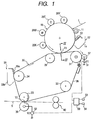
- Fig. 1 is a specific diagram illustrating the essential portion of an image forming apparatus according to an embodiment of the present invention
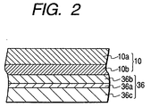
- Fig. 2 is an enlarged cross-sectional view taken along line II-II in Fig. 1.
- the image forming apparatus employs a developing unit of four color toners, for yellow, cyan, magenta and black, to form a full-color image.
- a photosensitive member 10 which serves as a latent image bearing member, is rotated by appropriate drive means (not shown) in the direction indicated by an arrow.
- a charge roller 11, which acts as charging means; developing rollers (Y, C, M and K), which act as developing means; an intermediate transfer unit 30; and cleaning means 12 are located on the periphery of the photosensitive member 10 in the rotational direction.
- the photosensitive member 10 includes a cylindrical conductive member 10a (see Fig. 2) on which is formed a photosensitive layer 10b.
- the charge roller 11 contacts the external surface of the photosensitive member 10 and uniformly electrifies it at -600 V, for example.
- the external surface of the photosensitive member 10, which is uniformly charged, is selectively exposed to light L by an exposing unit (not shown) in accordance with desired image information.
- the potential of the portion that is exposed to light L is reduced to approximately -100 V, for example, and an electrostatic latent image is formed thereat.
- the electrostatic latent image is developed into a visible toner image by the application of toner by the developing rollers 20. Since a development bias is applied to the developing rollers 20, toner having a negative polarity charge is attached to the portion whereat the potential has been reduced to develop the visible toner image.
- a developing roller 20Y for yellow, a developing roller 20C for cyan, a developing roller 20M for magenta, and a developing roller 20K for black are provided.
- the developing rollers 20Y, 20C, 20M and 20K can selectively contact the photosensitive member 10, and while in contact with the photosensitive member 10 can apply yellow, cyan, magenta and black toner to the surface of the photosensitive member 10 to develop the electrostatic latent image on the photosensitive member 10.
- the obtained toner image is first transferred to an intermediate transfer belt 36, which will be described later.
- the cleaning means 12 includes a cleaner blade 13 for scraping off residual toner that is attached to the external surface of the photosensitive member 10 after the transfer process, and a reservoir 14 in which toner scraped off by the cleaner blade 13 is retained.
- the intermediate transfer unit 30 includes a drive roller 31, four follow-up rollers 32, 33, 34 and 35, and the endless intermediate transfer belt 36 that is fitted around these rollers.
- the intermediate transfer belt 36 serves as an intermediate transfer member.
- the drive roller 31 is rotated at substantially the same peripheral speed as that of the photosensitive member 10 by using a gear (not shown) fixed to the end of the drive roller 31 to engage a driving gear (not shown) of the photosensitive member 10.
- the intermediate transfer belt 36 is rotationally fed in the direction indicated by an arrow at substantially the same peripheral speed as that of the photosensitive member 10.
- the follow-up roller 35 is located at a position at which, with a force produced by tension, the intermediate transfer belt 36 is pressed against the photosensitive member 10 in the interval between the follow-up roller 35 and the drive roller 31, and the first transfer point T1 is provided at the portion where the intermediate transfer belt 36 contacts the photosensitive member 10.
- the follow-up roller 35 is located near the first transfer point T1, upstream, in the feeding direction of the intermediate transfer belt 36.
- An electrode roller 37 is located opposite the drive roller 31 via the intermediate transfer belt 36, and a first transfer voltage V1 of, for example, +500 V provided by a constant voltage power source 51 is applied through the electrode roller 37 to a conductive layer 36a of the intermediate transfer belt 36 that will be described later.
- the follow-up roller 32 is a tension roller that employs urging means (not shown) to force the intermediate transfer belt 36 in the direction of the tension.
- the follow-up roller 33 is a backup roller for forming the second transfer point T2.
- a second transfer roller 38 is positioned opposite the backup roller 33, via the intermediate transfer belt 36, as a second transfer member.
- the second transfer roller 38 can be separated from the intermediate transfer belt 36 by a separation mechanism (not shown).
- a power supply device 52 is connected as voltage application means to the second transfer roller 38.
- the power supply device 52 applies to the second transfer roller 38 a second transfer voltage V2 (e.g., +1000 V) that has the same polarity as the first transfer voltage V1 but that has a greater absolute value than has the first transfer voltage V1.
- V2 e.g., +1000 V
- the power supply device 52 halts the application of a voltage to the second transfer roller 38 while applying the first transfer voltage V1 to the intermediate transfer belt 36, i.e., the power supply device 52 halts the application of the second transfer voltage V2.
- the power supply device 52 is a power source of a current sink type.
- the follow-up roller 34 is a backup roller for a belt cleaner 39.
- the belt cleaner 39 includes a cleaner blade 39a, which contacts the intermediate transfer belt 36 and scrapes off residual toner that is attached to the external surface of the belt 36, and a reservoir 39b, which is used to retain the toner scraped off by the cleaner blade 39a.
- the belt cleaner 39 can be separated from the intermediate transfer belt 36 by a separation mechanism (not shown).
- the intermediate transfer belt 36 is a composite layer belt including a conductive layer 36a and a resistance layer 36b, which is integrally formed with the conductive layer 36a and which is pressed against the photosensitive member 10.
- the conductive layer 36a is integrally formed with an insulating base member 36c made of synthetic resin, and the first transfer voltage V1 is applied to the conductive layer 36a via the previously described electrode roller 37.
- the resistance layer 36b which has the shape of a belt, is exposed by removing a corresponding portion along the side edge of the belt 36 so that the electrode roller 37 contacts the exposed portion.
- the toner image on the photosensitive member 10 is transferred to the intermediate transfer belt 36 at the first transfer point T1, and the toner image on the intermediate transfer belt 36 is then transferred to a recording medium S, such as paper, that is fed between the belt 36 and the second transfer roller 38 at the second transfer point T2.
- the recording medium S is fed by a paper feeding device (not shown), and is conveyed by a gate roller pair 40 to the second transfer point T2 at a predetermined timing.
- a temperature sensor 53 and a humidity sensor 54 connected to a controller 50, which controls the entire operation of the image forming apparatus, is a temperature sensor 53 and a humidity sensor 54.
- the controller 50 can be so designed that the first transfer voltage V1 and the second transfer voltage V2 are determined as needed in accordance with the temperature and humidity detected by the sensors 53 and 54.
- the image forming apparatus in this embodiment is so designed that when the peripheral speed of the intermediate transfer belt 36 is defined as Vp (mm/s), the resistance of the resistance layer 36b is defined as Rit, and the resistance of the second transfer roller 38 is defined as Rt2, the following condition is satisfied: 1 x 10 11 /Vp ⁇ Rit + Rt2 ⁇ 1 x 10 9 /Vp.
- the operation of the thus arranged image forming apparatus is as follows.
- the application of the second transfer voltage V2 to the second transfer roller 38 is halted at an appropriate timing (or a voltage is applied tat has the same polarity as the first transfer voltage V1 and that has a smaller absolute value than has the first transfer voltage V1), while the second transfer roller 38 is pressed against the intermediate transfer belt 36 and the first transfer voltage V1 is applied to the intermediate transfer belt 36.
- a potential difference e.g., about +500 V
- the toner attached to the second transfer roller 38 is transferred to the intermediate transfer belt 36, so that the second transfer roller 38 is cleaned.
- the toner transferred to the intermediate transfer roller 36, together with the toner that remains on the intermediate transfer bell 36 after the second transfer is removed when the belt cleaner 39 is brought into contact with the intermediate transfer belt 36.
- the toner image is fixed to the recording medium S by passing the recording medium S through a fixing unit (not shown), and the recording medium S is then discharged outside the apparatus.
- FIG. 3 One example of application timings for various voltages and of separation timing for the second transfer roller 38 is shown in Fig. 3.
- Fig. 3 is a timing chart for a process wherein a color image is sequentially transferred to two recording media S, and the second transfer roller 38 is thereafter cleaned.
- a print command signal (image forming signal) is transmitted by a host computer (personal computer) (not shown) to the controller 50 of the image forming apparatus, which in turn rotates the photosensitive member 10, the developing rollers 20 and the intermediate transfer belt 36. Then, at predetermined time t1 charging by the charge roller 11 is initiated. Thereafter, the above described exposure using the light L is performed, which is not shown in Fig. 3.
- the first transfer voltage V1 is applied.
- the developing roller 20Y for the first recording medium contacts the photosensitive member 10 and the developing bias voltage is applied.
- the developing roller 20Y is separated from the photosensitive member 10 and the application of the developing bias voltage is halted.
- the developing roller 20M for the first recording medium contacts the photosensitive member 10 and the developing bias voltage is applied.
- the developing roller 20M is separated from the photosensitive member 10 and the application of the developing bias voltage is halted.
- the developing roller 20C for the first recording medium contacts the photosensitive member 10 and the developing bias voltage is applied.
- the developing roller 20C is separated from the photosensitive member 10 and the application of the developing bias voltage is halted.
- the developing roller 20K for the first recording medium contacts the photosensitive member 10 and the developing voltage is applied.
- the second transfer voltage V2 for the first recording medium is applied, and the second transfer roller 38 is pressed against the intermediate transfer belt 36.
- the developing roller 20Y for the second recording medium contacts the photosensitive member 10 and the developing bias voltage is applied.
- the second transfer voltage V2 is applied. Also as is apparent from Fig. 1, since the distance between the development position for the fourth color (the position of the developing roller 20K) and the first transfer point T1 is comparatively short, the first transfer of the toner image for the fourth color (K) and the second transfer of the toner image (fill-color image) that has been transferred to the intermediate transfer belt 36 are simultaneously performed at a specific time.
- the developing roller 20K is separated from the photosensitive member 10 and the application of the developing bias voltage is halted.
- the application of the second transfer voltage V2 for the first recording medium is halted, and the second transfer roller 38 is separated from the intermediate transfer belt 36.
- the developing roller 20Y for the second recording medium is separated from the photosensitive member 10
- the application of the developing bias voltage is halted
- the developing roller 20M for the second recording medium contacts the photosensitive member 10, and the developing bias voltage is applied.
- the time (T9), at which the developing roller 20Y has completed the development of the second recording medium, is substantially the same as the time at which the application of the second transfer voltage V2 is halted. However, since the time at which the first transfer of the toner image formed by the developing roller 20Y is completed is later than time t9, the application of the second transfer voltage is halted for a period during which the toner image formed by the developing roller 20Y is first transferred.
- the toner images are formed on the photosensitive member 10 in the order Y, M, C and K, and are first transferred to the intermediate transfer belt 36 to form a color image, which is then transferred to the first recording medium S.
- the development and the first transfer are performed in a period extending from time t3 to time t7.
- the development and the first transfer of the final color K, and the collective second transfer of all the colors are performed for the first recording medium, and also the development for the first color Y is performed for the second recording medium.
- the developing roller 20M for the second recording medium is separated from the photosensitive member 10 and the application of the developing bias voltage is halted. Also, the developing roller 20C for the second recording medium contacts the photosensitive member 10 and the developing bias voltage is applied.
- the developing roller 20C for the second recording medium is separated from the photosensitive member 10 and the application of the developing bias voltage is halted.
- the developing roller 20K for the second recording medium contacts the photosensitive member 10 and the developing bias voltage is applied.
- the second transfer voltage V2 for the second recording medium is applied, and the second transfer roller 38 is pressed against the intermediate transfer belt 36.
- the developing roller 20K for the second recording medium is separated from the photosensitive member 10 and the application of the developing bias voltage is halted.
- the second transfer roller 38 is cleaned each time an image is transferred to two recording media.
- the second transfer roller 38 is cleaned each time images have been transferred to two recording media; however, in a period extending from time t9 to time t12, the second transfer roller 38 may be pressed against the intermediate transfer belt 36 without the second transfer voltage V2 being applied, and the second transfer roller 38 may be cleaned each time an image is transferred to a recording medium.
- the above described image forming operation for the second recording medium is repeated, i.e., at time t12, the developing roller 20Y for the third recording medium contacts the photosensitive member 10 and the application of the developing bias voltage is begun, and at time t14 the developing roller 20M for the third recording medium contacts the photosensitive member 10 and the application of the developing bias voltage is initiated.
- the first transfer voltage V1 is set as a constant voltage of +500 V
- the second transfer voltage V2 is set as a constant voltage of +800 V with a constant current of +30 ⁇ A and a small impedance.
- the second transfer voltage V2 is not applied to the second transfer roller 38 during the cleaning.
- a current flowing across the intermediate transfer belt 36 and the second transfer roller 38 is set to approximately -10 ⁇ A.
- the intermediate transfer belt 36 is formed in the following manner.
- the insulating base member 36c is fabricated from a PET sheet; and the conductive layer 36c is formed thereon by AL evaporation.
- a coat of paint having a thickness of 10 to 100 ⁇ m, wherein fluorine particles and SnO 2 , which is a conductive agent, are dispersed in urethane as a base material, is applied to the resultant structure, thereby forming the conductive layer 36.
- both ends of the belt shaped conductive layer 36 are bonded together by ultrasonic welding to form an endless belt.
- a coat of the paint is applied, except along the side edge of the belt, so that the belt shaped conductive layer 36 is exposed and the electrode roller 37 can contact the exposed portion.
- the surface resistivity of the resistance layer 36b is approximately 10 8 to 10 15 ⁇ /cm, the volume resistivity is approximately 10 7 to 10 14 ⁇ cm, and the surface roughness is equal to or less than Rmax 1 ⁇ m (more preferably, equal to or less than 0.7 ⁇ m).
- the depth (the thrust depth) to which the photosensitive member 10 is pressed against the intermediate transfer belt 36 is 1.2 ⁇ 0.5 mm.
- a current sink constant-voltage source or a constant-voltage source having a bypass resistor, is employed as a power source. It is preferable that a con*21+* voltage value be determined based on the outputs of the temperature sensor and humidity sensors 53 and 54.
- the electrode roller 37 that is employed has a resistance of 1 M ⁇ or less.
- a constant-voltage source is employed to control the lower limit voltage.
- the second transfer roller 38 is rendered conductive by an ionic conductive agent.
- the resistance is 10 6 to 10 8 ⁇
- the hardness is 60 ⁇ 5°
- the pressing load on the backup roller 33 is 5.0 to 9.0 kg (more preferably, about 7.0 kg).
- a high density pigment toner having a particle size of 7 ⁇ m is employed.
- the amount of an additive having a large particle size is 0.5 to 4.0 wt% (more preferably 0.7 wt%), and the amount of an additive having a small particle size is 1.5 to 4.0 wt% (more preferably 2.0 wt%).
- the additive having a large particle size is required mainly to improve the durability and stability of the toner. Although more of this additive is better, the amount of the additive should not exceed 4.0 wt%, otherwise the flowability of toner is deteriorated, and transfer hollows and other faults are caused.
- the additive having a small particle size is required mainly to improve the transfer of rough paper. Although more of this additive is better, the amount of the additive should not exceed 4.0 wt%, otherwise, due to floating silica, a film tends to be formed on the photosensitive member 10 and the intermediate transfer belt 36.
- the flowability of the toner is approximately AD 0.35 g/cc, and the amount of a charge is -10 ⁇ g/cm 2 or smaller.
- the amount of toner deposited before the second transfer i.e., the amount of toner on the intermediate transfer belt 36, is 1.5 mg/cm 2 or less.
- the outer diameter of the drive roller 31 is so set that the peripheral speed of the intermediate transfer belt 36 is slightly higher (including a tolerance) than that of the photosensitive member 10, specifically, 0.6 ⁇ 0.5 % higher.
- the peripheral speed of the photosensitive member 10 correspond exactly to that of the intermediate transfer belt 36 to which the toner image is transferred from the photosensitive member 10.
- the outre diameter of the drive roller 31 is so set that the peripheral speed of the intermediate transfer belt 36 is slightly higher (within the tolerance) than that of the photosensitive member 10.
- the intermediate transfer belt 36 even tough slightly, is held constantly taut at the interval between the drive roller 3 1 and the position (first transfer point T1) whereat the photosensitive member 10 is pressed against the intermediate transfer belt 36, so that at the first transfer point T1 the state of the intermediate transfer belt 36 is stable.
- Urethan is coated on the external surface of the drive roller 31 in order to increase a friction coefficient.
Landscapes
- Physics & Mathematics (AREA)
- General Physics & Mathematics (AREA)
- Electrostatic Charge, Transfer And Separation In Electrography (AREA)
- Laminated Bodies (AREA)
Priority Applications (1)
| Application Number | Priority Date | Filing Date | Title |
|---|---|---|---|
| EP06005125A EP1698947A1 (fr) | 1998-07-21 | 1999-07-21 | Appareil de formation d'images avec une bande de transfert intermédiaire et son procédé de fabrication |
Applications Claiming Priority (2)
| Application Number | Priority Date | Filing Date | Title |
|---|---|---|---|
| JP22102798A JP3913904B2 (ja) | 1998-07-21 | 1998-07-21 | 画像形成装置 |
| JP22102798 | 1998-07-21 |
Related Child Applications (1)
| Application Number | Title | Priority Date | Filing Date |
|---|---|---|---|
| EP06005125A Division EP1698947A1 (fr) | 1998-07-21 | 1999-07-21 | Appareil de formation d'images avec une bande de transfert intermédiaire et son procédé de fabrication |
Publications (2)
| Publication Number | Publication Date |
|---|---|
| EP0974877A2 true EP0974877A2 (fr) | 2000-01-26 |
| EP0974877A3 EP0974877A3 (fr) | 2001-07-25 |
Family
ID=16760347
Family Applications (2)
| Application Number | Title | Priority Date | Filing Date |
|---|---|---|---|
| EP06005125A Withdrawn EP1698947A1 (fr) | 1998-07-21 | 1999-07-21 | Appareil de formation d'images avec une bande de transfert intermédiaire et son procédé de fabrication |
| EP99114350A Withdrawn EP0974877A3 (fr) | 1998-07-21 | 1999-07-21 | Appareil de formation d'images |
Family Applications Before (1)
| Application Number | Title | Priority Date | Filing Date |
|---|---|---|---|
| EP06005125A Withdrawn EP1698947A1 (fr) | 1998-07-21 | 1999-07-21 | Appareil de formation d'images avec une bande de transfert intermédiaire et son procédé de fabrication |
Country Status (3)
| Country | Link |
|---|---|
| US (1) | US6112038A (fr) |
| EP (2) | EP1698947A1 (fr) |
| JP (1) | JP3913904B2 (fr) |
Families Citing this family (5)
| Publication number | Priority date | Publication date | Assignee | Title |
|---|---|---|---|---|
| JP3975049B2 (ja) * | 2000-07-10 | 2007-09-12 | 株式会社リコー | 転写装置及び画像形成装置 |
| US20040086305A1 (en) * | 2002-10-31 | 2004-05-06 | Samsung Electronics Co. Ltd. | Image transfer belt having a polymeric coating on a conductive substrate on a polymeric film |
| US7106997B2 (en) * | 2002-11-29 | 2006-09-12 | Samsung Electronics Co., Ltd. | Intermediate transfer member for carrying intermediate electrophotographic image |
| US6954606B2 (en) * | 2003-04-18 | 2005-10-11 | Lexmark International, Inc. | Polyurethane coatings and drive rollers including the same |
| US7177560B2 (en) | 2003-09-24 | 2007-02-13 | Seiko Epson Corporation | Method of warming fixing device, method of determining humidity value used in image formation apparatus, and image formation apparatus |
Family Cites Families (8)
| Publication number | Priority date | Publication date | Assignee | Title |
|---|---|---|---|---|
| JPH0540417A (ja) * | 1991-08-07 | 1993-02-19 | Seiko Epson Corp | 中間転写型記録装置 |
| US5586304A (en) * | 1994-09-08 | 1996-12-17 | Compaq Computer Corporation | Automatic computer upgrading |
| JP3416389B2 (ja) * | 1996-04-26 | 2003-06-16 | キヤノン株式会社 | 画像形成装置 |
| JPH1078689A (ja) * | 1996-07-08 | 1998-03-24 | Ricoh Co Ltd | 画像形成装置 |
| JPH1097148A (ja) * | 1996-08-02 | 1998-04-14 | Canon Inc | 画像形成装置 |
| JP3507305B2 (ja) * | 1996-11-01 | 2004-03-15 | キヤノン株式会社 | 画像形成装置 |
| JPH1184910A (ja) * | 1997-07-11 | 1999-03-30 | Canon Inc | 画像形成装置 |
| EP0919884B1 (fr) * | 1997-11-28 | 2005-05-11 | Seiko Epson Corporation | Appareil de formation d'images |
-
1998
- 1998-07-21 JP JP22102798A patent/JP3913904B2/ja not_active Expired - Fee Related
-
1999
- 1999-07-20 US US09/357,392 patent/US6112038A/en not_active Expired - Fee Related
- 1999-07-21 EP EP06005125A patent/EP1698947A1/fr not_active Withdrawn
- 1999-07-21 EP EP99114350A patent/EP0974877A3/fr not_active Withdrawn
Non-Patent Citations (3)
| Title |
|---|
| PATENT ABSTRACTS OF JAPAN vol. 017, no. 332 (P-1562), 23 June 1993 (1993-06-23) & JP 05 040417 A (SEIKO EPSON CORP), 19 February 1993 (1993-02-19) * |
| PATENT ABSTRACTS OF JAPAN vol. 1998, no. 03, 27 February 1998 (1998-02-27) & JP 09 292777 A (CANON INC), 11 November 1997 (1997-11-11) & US 5 809 287 A (TAKEUCHI) 15 September 1998 (1998-09-15) * |
| PATENT ABSTRACTS OF JAPAN vol. 1998, no. 08, 30 June 1998 (1998-06-30) & JP 10 078689 A (RICOH CO LTD), 24 March 1998 (1998-03-24) * |
Also Published As
| Publication number | Publication date |
|---|---|
| JP3913904B2 (ja) | 2007-05-09 |
| US6112038A (en) | 2000-08-29 |
| EP1698947A1 (fr) | 2006-09-06 |
| JP2000039780A (ja) | 2000-02-08 |
| EP0974877A3 (fr) | 2001-07-25 |
Similar Documents
| Publication | Publication Date | Title |
|---|---|---|
| EP0919884B1 (fr) | Appareil de formation d'images | |
| US6016418A (en) | Image forming apparatus | |
| US6112038A (en) | Image forming apparatus having a stable potential at a first transfer point | |
| CN1069419C (zh) | 成象装置 | |
| JP3632409B2 (ja) | 画像形成装置 | |
| JP3702627B2 (ja) | 画像形成装置 | |
| JP3502967B2 (ja) | 画像形成装置 | |
| JPH11153910A (ja) | 画像形成装置 | |
| JP2002202670A (ja) | 画像形成装置 | |
| JP3272126B2 (ja) | 一成分現像装置 | |
| US6330408B1 (en) | Transfer apparatus | |
| JPH0627831A (ja) | 画像形成装置 | |
| JPH05303289A (ja) | 画像形成装置 | |
| JP3695134B2 (ja) | 画像形成装置 | |
| JP3074506B2 (ja) | 画像形成装置 | |
| JPH11161062A (ja) | 画像形成装置 | |
| JPH11282286A (ja) | 画像形成装置 | |
| JPH11288178A (ja) | 画像形成装置 | |
| JP3666009B2 (ja) | 画像形成装置 | |
| JP3620564B2 (ja) | 画像形成装置 | |
| JPH11288179A (ja) | 画像形成装置 | |
| JPH0922194A (ja) | 湿式現像装置 | |
| JPH11282263A (ja) | 画像形成装置 | |
| JPH11282288A (ja) | 画像形成装置 | |
| JPH11282282A (ja) | 画像形成装置 |
Legal Events
| Date | Code | Title | Description |
|---|---|---|---|
| PUAI | Public reference made under article 153(3) epc to a published international application that has entered the european phase |
Free format text: ORIGINAL CODE: 0009012 |
|
| AK | Designated contracting states |
Kind code of ref document: A2 Designated state(s): AT BE CH CY DE DK ES FI FR GB GR IE IT LI LU MC NL PT SE |
|
| AX | Request for extension of the european patent |
Free format text: AL;LT;LV;MK;RO;SI |
|
| PUAL | Search report despatched |
Free format text: ORIGINAL CODE: 0009013 |
|
| AK | Designated contracting states |
Kind code of ref document: A3 Designated state(s): AT BE CH CY DE DK ES FI FR GB GR IE IT LI LU MC NL PT SE |
|
| AX | Request for extension of the european patent |
Free format text: AL;LT;LV;MK;RO;SI |
|
| 17P | Request for examination filed |
Effective date: 20010906 |
|
| AKX | Designation fees paid |
Free format text: AT BE CH CY DE DK ES FI FR GB GR IE IT LI LU MC NL PT SE |
|
| 17Q | First examination report despatched |
Effective date: 20030424 |
|
| STAA | Information on the status of an ep patent application or granted ep patent |
Free format text: STATUS: THE APPLICATION IS DEEMED TO BE WITHDRAWN |
|
| 18D | Application deemed to be withdrawn |
Effective date: 20060804 |