EP0975152A2 - Systeme de caméra vidéo avec contrôle d'exposition - Google Patents
Systeme de caméra vidéo avec contrôle d'exposition Download PDFInfo
- Publication number
- EP0975152A2 EP0975152A2 EP99120635A EP99120635A EP0975152A2 EP 0975152 A2 EP0975152 A2 EP 0975152A2 EP 99120635 A EP99120635 A EP 99120635A EP 99120635 A EP99120635 A EP 99120635A EP 0975152 A2 EP0975152 A2 EP 0975152A2
- Authority
- EP
- European Patent Office
- Prior art keywords
- video camera
- luminance
- average value
- information
- light measurement
- Prior art date
- Legal status (The legal status is an assumption and is not a legal conclusion. Google has not performed a legal analysis and makes no representation as to the accuracy of the status listed.)
- Granted
Links
Images


Classifications
-
- G—PHYSICS
- G01—MEASURING; TESTING
- G01S—RADIO DIRECTION-FINDING; RADIO NAVIGATION; DETERMINING DISTANCE OR VELOCITY BY USE OF RADIO WAVES; LOCATING OR PRESENCE-DETECTING BY USE OF THE REFLECTION OR RERADIATION OF RADIO WAVES; ANALOGOUS ARRANGEMENTS USING OTHER WAVES
- G01S3/00—Direction-finders for determining the direction from which infrasonic, sonic, ultrasonic or electromagnetic waves, or particle emission, not having a directional significance, are being received
- G01S3/78—Direction-finders for determining the direction from which infrasonic, sonic, ultrasonic or electromagnetic waves, or particle emission, not having a directional significance, are being received using electromagnetic waves other than radio waves
- G01S3/782—Systems for determining direction or deviation from predetermined direction
- G01S3/785—Systems for determining direction or deviation from predetermined direction using adjustment of orientation of directivity characteristics of a detector or detector system to give a desired condition of signal derived from that detector or detector system
- G01S3/786—Systems for determining direction or deviation from predetermined direction using adjustment of orientation of directivity characteristics of a detector or detector system to give a desired condition of signal derived from that detector or detector system the desired condition being maintained automatically
- G01S3/7864—T.V. type tracking systems
-
- H—ELECTRICITY
- H04—ELECTRIC COMMUNICATION TECHNIQUE
- H04N—PICTORIAL COMMUNICATION, e.g. TELEVISION
- H04N23/00—Cameras or camera modules comprising electronic image sensors; Control thereof
- H04N23/70—Circuitry for compensating brightness variation in the scene
-
- H—ELECTRICITY
- H04—ELECTRIC COMMUNICATION TECHNIQUE
- H04N—PICTORIAL COMMUNICATION, e.g. TELEVISION
- H04N23/00—Cameras or camera modules comprising electronic image sensors; Control thereof
- H04N23/70—Circuitry for compensating brightness variation in the scene
- H04N23/71—Circuitry for evaluating the brightness variation
-
- H—ELECTRICITY
- H04—ELECTRIC COMMUNICATION TECHNIQUE
- H04N—PICTORIAL COMMUNICATION, e.g. TELEVISION
- H04N23/00—Cameras or camera modules comprising electronic image sensors; Control thereof
- H04N23/70—Circuitry for compensating brightness variation in the scene
- H04N23/72—Combination of two or more compensation controls
-
- H—ELECTRICITY
- H04—ELECTRIC COMMUNICATION TECHNIQUE
- H04N—PICTORIAL COMMUNICATION, e.g. TELEVISION
- H04N5/00—Details of television systems
- H04N5/76—Television signal recording
- H04N5/765—Interface circuits between an apparatus for recording and another apparatus
- H04N5/77—Interface circuits between an apparatus for recording and another apparatus between a recording apparatus and a television camera
Definitions
- the present invention relates to video cameras, and in particular to techniques for following a change of an object in the field of view of a video camera and for controlling the exposure so as to adjust the luminance of the object.
- Numerous methods may be employed for controlling the exposure of a video camera.
- such methods may include an automatic multi-split light measurement exposure control method, an automatic centralised or spot light measurement exposure control method, a manual exposure control method and so forth.
- the automatic multi-split light measurement exposure control method utilizes a multi-split light measurement pattern to measure luminance information obtained from picture information.
- the measured luminance information may be processed to obtain an average value, a distribution, and/or a histogram of such luminance information which may be utilized to control exposure.
- the automatic centralized or spot light measurement exposure control method utilizes a light measurement pattern which may be respectively located in or around the center portion of a screen and in a relatively small or spot area in or around such center portion. Luminance information obtained from picture information is measured by use of the light measurement pattern which may be utilized to control exposure.
- an operator or cameraman may determine and/or manually adjust the luminance of an object to be photographed to obtain a desired or acceptable value.
- the automatic multi-split light measurement exposure control method may have difficultly in obtaining a proper exposure of an object in a scene having a relatively large luminance difference between the object and its background (such as in a scene having a backlight or excessive normal light).
- the background information may be incorporated with information of the object to be photographed, thereby making it difficult to obtain a proper exposure of the object.
- the automatic centralized or spot light measurement exposure control method such method may be difficult to use when the object to be photographed is moving. That is, in such method, the operator or cameraman has to photograph the object such that it is always located at the center of a screen.
- a video camera system comprises a picture information temporary storage device having a temporary memory for dividing a video signal obtained from at least one video camera into luminance information and color information and for storing picture information composed of the luminance information and the color information in the temporary memory at an arbitrary timing; an object recognizing and tracking device for recognizing, extracting and tracking a displayed object from the picture information stored in the temporary memory; a tracked object initialization device for storing characteristic values of the tracked object; a tracked object extraction and light measurement device for extracting and integrating only the luminance information of the tracked object and for calculating an average value; a recognized color extraction and light measurement device for extracting color information having the same color as the recognized object, integrating the corresponding luminance information, and calculating an average value; a centralized light measurement device for integrating the luminance information of the object in or around the center portion of a screen and calculating an average value; a spot light measurement device for integrating the luminance information in a relatively small area in or around the
- a video camera exposure control method comprises dividing a video signal obtained from a video camera into luminance information and color information and storing picture information including the luminance information and the color information in a temporary memory at an arbitrary timing; recognizing, extracting and tracking a displayed object from the picture information stored in the temporary memory; storing chacacteristic values of the tracked object; extracting and integrating only the luminance information of the traced object and calculating a first average value; extracting color information having the same color as the recognized object, integrating the corresponding luminance information, and calculating a second average value; integrating the luminance information of the object around the center portion of a screen and calculating a third average value; integrating the luminance information in a relatively small area around the center portion of the screen and calculating a fourth average value; selecting the luminance information of the first average value, the second average value, the third average value or the fourth average value in accordance with the object condition; and controlling an iris and/or an automatic
- the luminance information and color information stored in the picture information temporary storage device may be read out and supplied to the centralized light measurement device or spot light measurement device, the recognized color extraction and light measurement device, the object recognizing and tracking device, and the tracked object extraction and light measurement device in accordance with a command signal which may be supplied by the light-measuring method selection device.
- the recognized color extraction and light measurement device calculates a luminance average value of pixels having information which is relatively close to the recognized color.
- the object recognizing and tracking device and the tracked object extraction and light measurement device extract only the recognized object and calculate its average luminance value.
- the centralized light measurement device or spot light measurement device calculates a average luminance value of a center portion of a screen or in a relatively small area of such center portion, respectively.
- the light-measuring method selection device determines or selects a luminance average value from among the calculated luminance average values in accordance with the object condition or present operating conditions, and further selects a reference value.
- the selected luminance average value and reference value may be compared by the exposure control device so as to obtain a signal which may be utilized to properly adjust the luminance value of an object.
- a preferred embodiment of the present invention provides a system and method for properly controlling the exposure of a video camera for an object to be photographed, in which luminance values are selected from among a plurality of luminance values and in which the selected luminance values are utilized to control the exposure of the video camera; the plurality of luminance values preferably includes a plurality of average luminance values each calculated by a respective technique, as well as at least one reference luminance value.
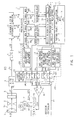
- Fig. 1 illustrates a video camera system (VCS) which is capable of performing object recognition and automatic exposure adjustment.
- VCS video camera system
- such VCS generally includes a lens block section 50, a sample and hold (S/H) and automatic gain control (AGC) circuit 4, an analog-to-digital (A/D) circuit 5, a luminance and color difference signal generator 6, an image temporary memory 7, a recognized color extraction and light measurement unit 9, an object recognizing and tracking unit 10, a tracked object extraction and light measurement unit 11, a tracked object initialization unit 8, a centralized light measurement/spot light measurement unit 12, a light-measuring method selector 15, an exposure controller 16 and a driver 17 which are connected as shown.
- the lens block section 50 includes a lens 1, an iris 2 and a solid pickup or charge coupled device (CCD) 3.
- CCD charge coupled device
- Image pickup light LA from an object is supplied through the lens 1 and the iris 2 to the CCD 3, whereupon a pickup signal S1 which represents a field-of-view picture is generated and supplied to the S/H and AGC 4.
- the S/H and AGC is adapted to sample and hold the received pickup signal S1 and to perform or adjust the gain thereof in accordance with an AGC control signal S16 from the exposure controller 16 so as to produce a pickup signal S2.
- pickup signal S2 is converted to a digital pickup signal S3 by the A/D converter 5.
- the digital pickup signal S3 is supplied to the luminance and color difference signal generator 6.
- the luminance and color difference signal generator 6 is adapted to receive the digital pickup signal S3 and to generate therefrom a luminance (Y) signal S4, a color difference (R-Y) signal S5 and a color difference (B-Y) signal S6.
- Such luminance and color difference signals are supplied to the image temporary memory 7, whereupon they are respectively preprocessed as an object tracking detection signal and an object luminance light-measuring signal.
- Such preprocessing may include a thinning out operation in which the number of samples of the luminance data are decreased, whereupon the total number of data bits processed are reduced thereby reducing or improving the sampling frequency and/or processing speed.
- the preprocessed signals are stored in an image memory or memories.
- three image memories 51, 52 and 53 may be utilized, wherein the luminance picture information is stored in the image memory 51, the color difference (R-Y) picture information is stored in the image memory 52, and the color difference (3-Y) picture information is stored in the image memory 53.
- Such stored picture information may be randomly-accessed by the centralized light measurement/spot light measurement unit 12, the recognized color extraction and light measurement unit 9, the object recognizing and tracking unit 10, and the tracked object extraction and light measurement unit 11. More specifically, when stored picture information is desired, the unit requesting such information supplies a signal, such as an address signal (ad1, ad2 or ad3) which indicates the address or location of the desired stored picture information, to the image memories.
- the requested information is supplied to the respective unit by way of signal da1, da2 or da3.
- the unit 12 supplies a request or address signal ad1 to the image memory 51, whereupon signal da1 having the requested luminance picture information is supplied to the unit 12.
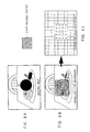
- the centralized light measurement/spot light measurement unit 12 receives the requested stored luminance picture information from the image temporary memory 7, as previously described, and generates therefrom an average value of the luminance information contained within a predetermined portion. For example, the centralized light measurement/spot light measurement unit 12 fray generate an average value of the luminance information in a center portion 98 of an image screen 97 which is indicated by a cross-hatched or shaded portion in Fig. 2.
- the center portion or area 98 has a size of X/3 x Y/3, in which the horizontal dimension of the screen 97 is X and the vertical dimension of the screen is Y.
- the centralized light measurement unit 12 supplies the generated average value of the center luminance information (which may be referred to as a centralized light measurement) as an output signal S7 to one terminal of a switch swl of the light-measuring method selector 15.
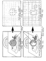
- FIG. 4A illustrates a image on which the unit 12 is to determine an average value of the center luminance information.
- the light measured or center portion of such image is indicated as a shaded area in Fig. 4B.
- the information contained within this shaded area is processed by the unit 12 so as to determine the centralized light measurement or average luminance levels (light values) as illustrated in Fig. 4C.
- the centralized light measurement unit/spot light measurement unit 12 may further generate an average value of the luminance information obtained from the signal dal pertaining to a relatively small predetermined portion or spot of the image screen 97.
- Such predetermined portion may be at the center portion of the image screen 97 as, for example, indicated by a shaded portion 99 in Fig. 3.
- the unit 12 determines an average value of the luminance information contained within the center portion or area having a size of X/10 x Y/10 (in which the horizontal dimension of the screen 97 is X and the vertical dimension of the screen is Y).
- Such area 99 is smaller or narrower than the area 98 of Fig. 2.
- the spot light measurement unit 12 supplies the generated average value of the center spot luminance information (which may be referred to as a spot light measurement) as the output signal S7 to one terminal of the switch SW1 of the light-measuring method selector 15.
- the object recognizing and tracking unit 10 may receive the luminance information signal da1 and the color difference information signals da2 and da3 from the image temporary memory 7.
- the object recognizing and tracking unit 10 may further receive an instructing or trigger signal S17,
- the object recognizing and tracking unit 10 extracts and holds characteristic values or information, which may include position information, of a desired object contained within the image represented by the respective luminance and color difference signals in a hold area of the unit 10.
- the hue of such object, or recognized hue is supplied to the recognized colar extraction and light measurement unit 9.
- the tracked object extraction and light measurement unit 11 may receive an instructing signal S17 and information pertaining to the recognized and tracked object from the object recognizing and tracking unit 10.
- the tracked object extraction and light measurement unit 11 may integrate only the luminance information of tne object extracted by the object recognizing and tracking unit 10 and average the same so as to form an average value S9.
- Such average value S9 is supplied from the tracked object extraction and light measurement unit 11 to one terminal of a switch sw3 of the light-measuring method selector 15.
- An example of the procedure performed by the tracked object extraction and light measurement unit 11 is illustrated in Figs. 5A and 5B.
- the center piece of fruit or apple of the image of Fig. 4A is the recognized or tracked object and, as such, is shown as a shaded object in Fig. 5A.
- the information contained within this shaded area is processed by the unit 11 so as to determine the light measurement or average luminance values as illustrated in Fig. 5B.
- the tracked object extraction and light measurement unit 11 may hold the luminance average value S9 of the tracked object in a hold area of the unit 11 and may cause such average value to be supplied to an object recognized color extraction/object recognizing, tracking and light-measuring reference luminance value generating circuit 13 so that a reference luminance value signal S10 may be produced therefrom.
- signal S10 which may represent an average of the luminance of the extracted object prior to autotracking, is supplied from the circuit 13 to one terminal of a switch sw4 of the light-measuring method selector 15.
- the recognized color extraction and light measurement unit 9 may receive the luminance information da1, the color difference information da2 and da3, and the recognized hue information from the object recognizing and tracking unit 10 as previously described.
- the unit 9 is adapted to process the received information so as to determine other locations or objects of the respective image (such as that of Fig. 4A) which have hues substantially similar to that of the recognized hue from the unit 10.
- the unit 9 extracts information from tne color difference signals R-Y and B-Y so as to determine locations or points having substantially the same hue as the recognized color among the luminance information da1 from the image memory 7, integrates the values of the determined points, averages the integrated values to obtain an averaged value S8, and supplies such average value S8 to one terminal of a switch sw2 of the light measuring method selector 15. To avoid or minimize count errors of the luminance of the same hue of noise component(s) in a black object or an environment color in a white object, black and environment colors may be checked.
- Figs. 5C and 5D An example of the procedure performed by the recognized color extraction and light measurement unit 9 is illustrated in Figs. 5C and 5D.
- the hue or color of the center piece of fruit (or apple) of Fig. 5A is the extracted or recognized color. Accordingly, the unit 9 determines other locations or objects within the image of Fig. 4A having substantially the same hue as that of the apple.
- objects such as the three cherries which have substantially the same color as that of the apple are identified or extracted. These objects are shaded in a similar manner to that of the apple as shown in Fig. 5C.
- the area of the apple having an oval shape which is not shaded represents an area which may be affected by so-called "white saturation" or "black crushing".
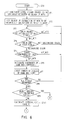
- Fig. 6 illustrates the processing in which luminance levels except a black portion and noise are averaged and the presence of an object is determined.
- Fig. 7 illustrates the processing wherein, in the presence of an object, Ymin/Ymax are set again to calculate Y average.
- step SP0 Processing is initiated in step SP0 and proceeds therefrom to steps SP1 and SP2 wherein a luminance level and a degree of saturation are respectively set. Thereafter, processing proceeds to step SP3 whereupon the degree of saturation of each pixel is checked. If the saturation is less than a predetermined amount, then processing returns to step SP3. If, however, the saturation is more than the predetermined amount, then processing proceeds to step SP4 wherein the hue of each pixel is checked. If tne hue is not the recognized color, then processing returns to step SP3. If the hue is the recognized color, then processing proceeds to step SP5 whereat the luminance of each pixel is checked. If the luminance is less than a prcdetermined amount, then processing returns to step SP3. However, if the luminance is more than the predetermined amount, then processing proceeds to step SP6 whereat the luminance values are integrated. Thereafter, the number of pixels having the same hue are counted at step SP7.
- step SP7 processing proceeds to step SP8, whereupon a determination is made as to whether all the pixels were observed. If such determination is negative, processing returns to step SP3. If, however, this determination is affirmative, processing proceeds to step SP9 wherein a determination is made as to whether the object is present by determining if the count number is less than a reference value.
- step SP9 If the determination in step SP9 is affirmative, processing proceeds to step SP21 wherein it is decided that there was no object. Thereafter, processing is terminated at step SP20.
- step SP9 determines whether the determination in step SP9 is negative. If the determination in step SP9 is negative, then processing proceeds to step SP10 wherein an average luminance value is calculated. Thereafter, processing proceeds to step SP11, whereupon upper and lower limits of the luminance are set.
- step SP14 the luminance of each pixel is checked. If the luminance is less than a predetermined amount or greater than another predetermined amount, then processing returns to step SP12. If, however, such luminance lies within a predetermined range, then processing proceeds to step SP15.
- step SP19 processing is terminated at step SP20.
- the tracked object initialization unit 8 produces the signal S17 which may be supplied to the object recognizing and tracking unit 10 and the tracked object extraction and light measurement unit 11 as previously described. Such signal S17 may start and/or stop automatic exposure adjustment and object tracking.
- the tracked object initialization unit 8 may include a memory switch 18 arranged on the body or housing of the video camera which, upon activating, may cause a signal to be transmitted therefrom which may cause the signal S17 to be produced and/or the previously-mentioned operations to be initiated.
- a recording start switch of the video camera, a signal from the recording start switch, or a memory switch of a radio or cable remote controller or the like may be utilized instead of the memory switch 18 arranged on the video camera body.
- the trigger signal S17 may be supplied to the object recognizing and tracking unit 10 so as to cause characteristic values to be extracted and held and the recognized hue to be supplied to the recognized color extraction and light measurement unit 9, and may also be supplied to the tracked object extraction and light measurement unit 11 so as to cause the luminance average value S9 of the tracked object to be held and an object recognized color extraction/object recognizing, tracking and light-measuring reference luminance value signal to be generated.
- the tracked object initialization unit a may generate a signal S19 and may supply the same to the light-measuring method selector 15.
- signal S19 provides an indication of one of a so-called pre-memory, memory and object tracking and exposure adjustment modes and the like to the light-measuring method selector 15.
- Such modes will be hereinafter more fully described with reference to steps SP31, SP35 and SP41-SP33 of Fig. 8.
- the light-measuring method selector 15 receives the signal S7 from the centralized light measurement/spot light measurement unit 12, the signal S8 from the recognized color and light measurement unit 9, the signal S9 from the tracked object extraction and light measurement unit 11, and the reference signal S10 from the reference luminance value unit 13. Additionally, the light-measuring method unit 15 receives a reference signal S11 from a centralized light measurement reference luminance value generating circuit 14. In particular, such circuit 14 supplies the signal S11 to one terminal of a switch sw5 of the light-measuring method selector 15.
- the circuit 14 may include a memory, such as read only memory (ROM), wherein the reference signal S11 is stored.
- the light-measuring method selector 15 receives signals S7, S8 and S9 which contain average values of luminance information respectively obtained from units 12, 9 and 10, and the light-measuring method selector 15 further receives reference value signals S10 and S11 from reference luminance value circuits 13 and 14.
- the light-measuring method selector 15 further receives the signal S19 from the tracked object initialization unit 8, as previously described.
- the light-measuring method selector 15 selects from among the luminance average values S7, S8 and S9 so as to form a selected signal S12, and selects from among luminance reference values S10 and S11 so as to form a selected reference signal S13.
- Such selection of signals may be performed by the selective opening and/or closing of switches sw1-sw5.
- the light-measuring method selector 15 may detect a tracked object unrecognizable or abnormal state in which a tracked object cannot be extracted by the tracked object extraction and light measurement unit 11. Such situation may occur, for example, during a white saturation or black crushing state which may result from a sudden luminance change or the like. In this situation, the light-measuring method selector 15 selects from among the luminance average value signals S7 and S8 from the centralized light measurement unit or spot light measurement unit 12 and the recognized color and light measurement unit 9, and the reference luminance value signals corresponding thereto, as luminance information to obtain or recover an operating state in which exposure may be controlled through tracked object extraction and light measurement.
- the light-measuring method selector 15 may further detect a state in which luminance other than that of a tracked object is abnormal, for example, an extreme saturation state or extreme black crushing state. Such situation or state may occur when the tracked object hides or moves off of the screen. In such situation, the light-measuring method selector 15 selects the luminance average value S7 from the centralized light measurement unit or spot light measurement unit 12 and the reference luminance value S11 (which corresponds to the signal S7) as luminance information.
- the light-measuring method selector 15 may select the signal S7 from the centralized light measurement unit or spot light measurement unit 12 and the reference luminance value S11 (corresponding to the signal S7) when the selector receives the instruction signal S19 from the tracked object initialization unit 8 prior to the initialization of an object as the luminance information.
- the luminance of the object to be recognized and extracted may be adjusted to an optimum exposure.
- the light-measuring method selector 15 may further provide a picture information update signal S18 after obtaining light measurement data. Such signal S18 is supplied to the picture information temporary memory 7.
- step SP30 a determination is made as to whether storing has begun. If the determination is affirmative, processing proceeds to step SP32 whereupon the light measurement value signal S7 from the unit 12 and the corresponding reference luminance value are selected. Thereafter, processing proceeds to step SP33 whereupon a picture information update signal S18 is generated and supplied to the memory 7.
- step SP31 determines whether it is the first time through such step. If it is the first time, processing proceeds to step SP36 wherein the characteristics of the recognized object are stored. processing then proceeds to step SP37 wherein the hue of the recognized color is stored. Thereafter, object recognition processing is performed in step SP38.
- the reference luminance value S10 is formed in step SP39. Processing then proceeds to step SP40 wherein the light measurement value signal S8 from the unit 9 and the corresponding reference luminance value are selected. Thereafter, processing proceeds to step SP33.
- step SP35 determines whether it is possible to extract the desired object. If it is possible, the light measurement value signal S9 and the corresponding reference luminance value are selected in step SP43. processing then proceeds to step SP33.
- step SP42 determines whether the object moves off of the screen. If such determination is affirmative, processing proceeds to step SP45 wherein the light measurement value signal S7 and the corresponding reference luminance value are selected. Processing then proceeds to step SP33. If, however, the determination in step SP44 is negative, processing proceeds to step SP46 wherein the light measurement value signal S9 from the unit 11 and the corresponding reference luminance value are selected. Processing then proceeds to step SP33.
- step SP33 Processing proceeds from step SP33 to step SP34, whereupon the selected signals are supplied to the exposure controller 16.
- the selected signals S12 and S13 from the light-measuring method selector 15 are respectively supplied to positive and negative inputs of a comparator or gain circuit 60 of the exposure controller 16, which may function as an error detector.
- the comparator 60 produces a compared or error signal S14 which is supplied to an iris/AGC circuit 61 which, in turn, produces an iris signal S15 and the AGC signal S16.
- the iris signal S15 is supplied to an iris driver circuit 17 so as to drive the iris, and the AGC signal S16 is supplied to the S/H and AGC circuit 4 as previously described.
- the exposure controller 16 may control the luminance and color difference signal generator 6.
- the present invention enables a light measurement to be obtained without being influenced by the background or other objects. Further, since the present invention enables an object to be light-measured while tracking, a cameraman photographing an object does not have to maintain such object in a light measurement area of a light measurement pattern. Furthermore, the present invention enables light measurement to be performed on the background around the center of an image screen when the object being photographed moves off the screen. As a result, normal luminance may be maintained.
- the present invention provides a video camera which determines a plurality of average values of luminance and a plurality of values of reference luminance values, and which selects therefrom the appropriate average luminance and reference luminance values in accordance with operating conditions. Such selected values are utilized to generate control signals for controlling or adjusting the exposure of the video camera so as to provide automatic and proper exposure control even when photographing under adverse or harsh conditions, such as, when backlight and excessive normal light (spot light) exists which may present serious problems for a conventional video camera.
- the present video camera was described as having a specific number of measurement units and reference value generating circuits, the present invention is not so limited. Instead, other numbers of such units and reference value generating circuits may be utilized.
Landscapes
- Engineering & Computer Science (AREA)
- Multimedia (AREA)
- Signal Processing (AREA)
- Physics & Mathematics (AREA)
- Electromagnetism (AREA)
- General Physics & Mathematics (AREA)
- Radar, Positioning & Navigation (AREA)
- Remote Sensing (AREA)
- Studio Devices (AREA)
- Exposure Control For Cameras (AREA)
- Color Television Image Signal Generators (AREA)
Applications Claiming Priority (3)
| Application Number | Priority Date | Filing Date | Title |
|---|---|---|---|
| JP33962494 | 1994-12-30 | ||
| JP6339624A JPH08186761A (ja) | 1994-12-30 | 1994-12-30 | ビデオカメラ装置及びビデオカメラ露出制御方法 |
| EP95309538A EP0720361B1 (fr) | 1994-12-30 | 1995-12-29 | Contrôle d'exposition pour caméras vidéo |
Related Parent Applications (1)
| Application Number | Title | Priority Date | Filing Date |
|---|---|---|---|
| EP95309538A Division EP0720361B1 (fr) | 1994-12-30 | 1995-12-29 | Contrôle d'exposition pour caméras vidéo |
Publications (3)
| Publication Number | Publication Date |
|---|---|
| EP0975152A2 true EP0975152A2 (fr) | 2000-01-26 |
| EP0975152A3 EP0975152A3 (fr) | 2000-07-05 |
| EP0975152B1 EP0975152B1 (fr) | 2003-04-23 |
Family
ID=18329264
Family Applications (2)
| Application Number | Title | Priority Date | Filing Date |
|---|---|---|---|
| EP99120635A Expired - Lifetime EP0975152B1 (fr) | 1994-12-30 | 1995-12-29 | Systeme de caméra vidéo avec contrôle d'exposition |
| EP95309538A Expired - Lifetime EP0720361B1 (fr) | 1994-12-30 | 1995-12-29 | Contrôle d'exposition pour caméras vidéo |
Family Applications After (1)
| Application Number | Title | Priority Date | Filing Date |
|---|---|---|---|
| EP95309538A Expired - Lifetime EP0720361B1 (fr) | 1994-12-30 | 1995-12-29 | Contrôle d'exposition pour caméras vidéo |
Country Status (6)
| Country | Link |
|---|---|
| US (1) | US5880782A (fr) |
| EP (2) | EP0975152B1 (fr) |
| JP (1) | JPH08186761A (fr) |
| KR (1) | KR960028218A (fr) |
| CN (1) | CN1078792C (fr) |
| DE (2) | DE69522197T2 (fr) |
Families Citing this family (53)
| Publication number | Priority date | Publication date | Assignee | Title |
|---|---|---|---|---|
| WO1999013376A1 (fr) * | 1997-09-11 | 1999-03-18 | Koninklijke Philips Electronics N.V. | Reglage d'iris |
| JP3481430B2 (ja) * | 1997-09-11 | 2003-12-22 | 富士通株式会社 | 移動体追跡装置 |
| US6424371B1 (en) * | 1997-09-24 | 2002-07-23 | Sheree H. Wen | Intelligent video monitor system |
| DE19743580B4 (de) * | 1997-10-02 | 2004-12-02 | Robert Bosch Gmbh | Verfahren und Anordnung zur Ermittlung der Lichtverhältnisse in Front eines beweglichen Fahrzeuges, insbesondere vor einem Kraftfahrzeug |
| US6380968B1 (en) | 1998-01-06 | 2002-04-30 | Intel Corporation | Method and apparatus for controlling a remote video camera in a video conferencing system |
| US6118113A (en) * | 1998-03-02 | 2000-09-12 | Hibbard; Earl Roger | Focusing mirror control system and method for adjusting same |
| JP4057147B2 (ja) * | 1998-06-16 | 2008-03-05 | コニカミノルタビジネステクノロジーズ株式会社 | 逆光シーン判定方法、逆光シーン判定方法プログラムを記憶したコンピュータにより読み取り可能な記憶媒体及び逆光シーン判定機能を有する画像処理装置 |
| KR100284305B1 (ko) * | 1998-10-28 | 2001-03-02 | 김영환 | 이미지 센서에서 녹색 화소의 평균값을 이용하여 화면의 밝기를조절하기 위한 장치 및 방법 |
| KR100495415B1 (ko) * | 1999-12-30 | 2005-06-14 | 매그나칩 반도체 유한회사 | 이미지 센서에서의 자동 노출 장치 |
| CH694952A5 (de) * | 2000-01-21 | 2005-10-14 | Volpi Ag | Verfahren zur Regelung der Leuchtdichte eines Betrachtungsfeldes bei der Endoskopie, sowie Endoskop und Blendenanordnung dafür. |
| JP4576658B2 (ja) * | 2000-02-29 | 2010-11-10 | ソニー株式会社 | 撮像装置、撮像方法及び撮像プログラム |
| US6765619B1 (en) * | 2000-04-04 | 2004-07-20 | Pixim, Inc. | Method and apparatus for optimizing exposure time in image acquisitions |
| US6701005B1 (en) | 2000-04-29 | 2004-03-02 | Cognex Corporation | Method and apparatus for three-dimensional object segmentation |
| US7342609B2 (en) * | 2000-05-09 | 2008-03-11 | Eastman Kodak Company | Exposure adjustment in an imaging apparatus |
| JP3615462B2 (ja) | 2000-05-12 | 2005-02-02 | 三洋電機株式会社 | 自動露光調節カメラ |
| US6704044B1 (en) * | 2000-06-13 | 2004-03-09 | Omnivision Technologies, Inc. | Completely integrated baseball cap camera |
| US6476865B1 (en) * | 2001-03-07 | 2002-11-05 | Eastman Kodak Company | Sparsely sampled image sensing device with color and luminance photosites |
| US6999126B2 (en) * | 2001-09-17 | 2006-02-14 | Mazzapica C Douglas | Method of eliminating hot spot in digital photograph |
| US8331621B1 (en) * | 2001-10-17 | 2012-12-11 | United Toll Systems, Inc. | Vehicle image capture system |
| US7725348B1 (en) * | 2001-10-17 | 2010-05-25 | United Toll Systems, Inc. | Multilane vehicle information capture system |
| JP2003255901A (ja) * | 2001-12-28 | 2003-09-10 | Sanyo Electric Co Ltd | 有機elディスプレイの輝度制御方法および輝度制御回路 |
| US7245320B2 (en) * | 2002-06-04 | 2007-07-17 | Micron Technology, Inc. | Method and apparatus for automatic gain and exposure control for maintaining target image brightness in video imager systems |
| WO2004017628A1 (fr) * | 2002-07-24 | 2004-02-26 | Matsushita Electric Industrial Co., Ltd. | Systeme capteur d'images |
| US7920718B2 (en) * | 2002-09-05 | 2011-04-05 | Cognex Corporation | Multi-zone passageway monitoring system and method |
| US20040189849A1 (en) * | 2003-03-31 | 2004-09-30 | Hofer Gregory V. | Panoramic sequence guide |
| JP4242691B2 (ja) * | 2003-04-15 | 2009-03-25 | オリンパス株式会社 | 固体撮像装置 |
| KR100510532B1 (ko) * | 2003-06-10 | 2005-08-26 | 삼성전자주식회사 | 베이어 패턴 컬러 신호에 대한 적응형 노이즈 제거 필터,이를 구비한 디지털 영상 신호 처리 장치, 및 그 방법 |
| JP4748702B2 (ja) * | 2003-06-10 | 2011-08-17 | 三星電子株式会社 | 輝度ノイズフィルタリング方法及び輝度ノイズフィルタリングシステム |
| JP4738778B2 (ja) * | 2003-10-15 | 2011-08-03 | 富士通テン株式会社 | 画像処理装置、運転支援装置および運転支援システム |
| US7623674B2 (en) * | 2003-11-05 | 2009-11-24 | Cognex Technology And Investment Corporation | Method and system for enhanced portal security through stereoscopy |
| US8326084B1 (en) * | 2003-11-05 | 2012-12-04 | Cognex Technology And Investment Corporation | System and method of auto-exposure control for image acquisition hardware using three dimensional information |
| CN1317671C (zh) * | 2003-11-26 | 2007-05-23 | 佳能株式会社 | 信号处理设备和控制方法 |
| JP4875833B2 (ja) * | 2004-03-16 | 2012-02-15 | オリンパス株式会社 | 撮像装置、画像処理装置、画像処理システム、及び画像処理方法 |
| JP4364903B2 (ja) * | 2004-03-17 | 2009-11-18 | 富士通マイクロエレクトロニクス株式会社 | 自動利得制御回路 |
| EP1594321A3 (fr) * | 2004-05-07 | 2006-01-25 | Dialog Semiconductor GmbH | Dispositif de prise d'images en couleur à plage dynamique étendue |
| JP4572583B2 (ja) | 2004-05-31 | 2010-11-04 | パナソニック電工株式会社 | 撮像装置 |
| US20050275737A1 (en) * | 2004-06-10 | 2005-12-15 | Cheng Brett A | System and method for effectively utilizing a live preview mode in an electronic imaging device |
| US7095892B2 (en) * | 2005-01-26 | 2006-08-22 | Motorola, Inc. | Object-of-interest image capture |
| JP2007060118A (ja) * | 2005-08-23 | 2007-03-08 | Casio Comput Co Ltd | 投影装置及び投影制御方法 |
| US8111904B2 (en) | 2005-10-07 | 2012-02-07 | Cognex Technology And Investment Corp. | Methods and apparatus for practical 3D vision system |
| JP2008135824A (ja) * | 2006-11-27 | 2008-06-12 | Matsushita Electric Ind Co Ltd | 位相調整装置、デジタルカメラおよび位相調整方法 |
| US7952021B2 (en) | 2007-05-03 | 2011-05-31 | United Toll Systems, Inc. | System and method for loop detector installation |
| US8126260B2 (en) * | 2007-05-29 | 2012-02-28 | Cognex Corporation | System and method for locating a three-dimensional object using machine vision |
| JP4424403B2 (ja) * | 2007-09-28 | 2010-03-03 | ソニー株式会社 | 撮像装置、撮像方法及び撮像プログラム |
| US20090278014A1 (en) * | 2008-05-06 | 2009-11-12 | Jim Allen | Overhead track system for roadways |
| CN101304489B (zh) * | 2008-06-20 | 2010-12-08 | 北京中星微电子有限公司 | 一种自动曝光方法及装置 |
| JP2011182304A (ja) * | 2010-03-03 | 2011-09-15 | Renesas Electronics Corp | 撮像装置及びその制御方法 |
| TWI438554B (zh) * | 2010-06-04 | 2014-05-21 | Hon Hai Prec Ind Co Ltd | 光圈控制系統 |
| CN102269913A (zh) * | 2010-06-07 | 2011-12-07 | 鸿富锦精密工业(深圳)有限公司 | 光圈控制系统 |
| US9413976B2 (en) * | 2012-08-08 | 2016-08-09 | Intuitive Surgical Operations, Inc. | Auto exposure of a camera in a surgical robot |
| EP3579545B1 (fr) | 2016-08-17 | 2021-02-24 | Google LLC | Ajustement de réglage de caméra basé sur des facteurs environnementaux prédits et systèmes de suivi l'utilisant |
| RU2667790C1 (ru) | 2017-09-01 | 2018-09-24 | Самсунг Электроникс Ко., Лтд. | Способ автоматической регулировки экспозиции для инфракрасной камеры и использующее этот способ вычислительное устройство пользователя |
| CN107707814A (zh) * | 2017-09-13 | 2018-02-16 | 华南理工大学 | 一种用于无线光通信的智能终端自动曝光控制方法及结构 |
Family Cites Families (11)
| Publication number | Priority date | Publication date | Assignee | Title |
|---|---|---|---|---|
| JPS5797275A (en) * | 1980-12-08 | 1982-06-16 | Sony Corp | Television camera |
| JPS6074878A (ja) * | 1983-09-30 | 1985-04-27 | Canon Inc | 光電変換器の蓄積時間補正装置 |
| JPH0664531B2 (ja) * | 1985-07-25 | 1994-08-22 | 日本電気株式会社 | 計算機システムの装置構成認識装置 |
| US5272538A (en) * | 1987-11-04 | 1993-12-21 | Canon Kabushiki Kaisha | Exposure control device |
| JP3113259B2 (ja) * | 1989-07-18 | 2000-11-27 | 富士写真フイルム株式会社 | ビデオカメラの露出制御方法及び装置 |
| US5194960A (en) * | 1990-03-05 | 1993-03-16 | Konica Corporation | Optical image signal control device |
| JP2766067B2 (ja) * | 1990-10-31 | 1998-06-18 | キヤノン株式会社 | 撮像装置 |
| US5347371A (en) * | 1990-11-29 | 1994-09-13 | Hitachi, Ltd. | Video camera with extraction unit for extracting specific portion of video signal |
| JPH06225328A (ja) * | 1993-01-27 | 1994-08-12 | Hitachi Ltd | 被写体抽出装置 |
| US5412487A (en) * | 1991-11-27 | 1995-05-02 | Hitachi, Ltd. | Video camera and apparatus for extracting an object |
| JP3412174B2 (ja) * | 1992-05-21 | 2003-06-03 | 松下電器産業株式会社 | 自動露光制御装置 |
-
1994
- 1994-12-30 JP JP6339624A patent/JPH08186761A/ja active Pending
-
1995
- 1995-12-27 US US08/578,076 patent/US5880782A/en not_active Expired - Lifetime
- 1995-12-29 EP EP99120635A patent/EP0975152B1/fr not_active Expired - Lifetime
- 1995-12-29 KR KR1019940072176A patent/KR960028218A/ko active Pending
- 1995-12-29 DE DE69522197T patent/DE69522197T2/de not_active Expired - Lifetime
- 1995-12-29 DE DE69530532T patent/DE69530532T2/de not_active Expired - Lifetime
- 1995-12-29 EP EP95309538A patent/EP0720361B1/fr not_active Expired - Lifetime
- 1995-12-30 CN CN95121761A patent/CN1078792C/zh not_active Expired - Fee Related
Also Published As
| Publication number | Publication date |
|---|---|
| DE69530532T2 (de) | 2004-03-25 |
| EP0720361B1 (fr) | 2001-08-16 |
| EP0975152A3 (fr) | 2000-07-05 |
| KR960028218A (ko) | 1996-07-22 |
| DE69530532D1 (de) | 2003-05-28 |
| EP0975152B1 (fr) | 2003-04-23 |
| US5880782A (en) | 1999-03-09 |
| JPH08186761A (ja) | 1996-07-16 |
| CN1159006A (zh) | 1997-09-10 |
| DE69522197D1 (de) | 2001-09-20 |
| CN1078792C (zh) | 2002-01-30 |
| EP0720361A3 (fr) | 1997-04-23 |
| EP0720361A2 (fr) | 1996-07-03 |
| DE69522197T2 (de) | 2002-05-02 |
Similar Documents
| Publication | Publication Date | Title |
|---|---|---|
| EP0975152B1 (fr) | Systeme de caméra vidéo avec contrôle d'exposition | |
| US7925047B2 (en) | Face importance level determining apparatus and method, and image pickup apparatus | |
| JP3540485B2 (ja) | 電子スチルカメラ | |
| JP3528202B2 (ja) | 電子スチルカメラ | |
| JP3368041B2 (ja) | 撮像装置 | |
| US5049997A (en) | Video camera exposure control method and apparatus for preventing improper exposure due to changing object size or displacement and luminance difference between the object and background | |
| US8004599B2 (en) | Automatic focus adjusting apparatus and automatic focus adjusting method, and image pickup apparatus and image pickup method | |
| CN101272505B (zh) | 摄像装置以及摄像方法 | |
| US20040061796A1 (en) | Image capturing apparatus | |
| JP2006074164A (ja) | 撮像装置 | |
| CN100508558C (zh) | 图像捕获设备及控制方法、图像处理设备 | |
| JP2528368B2 (ja) | カメラ | |
| US5325185A (en) | Apparatus and method for adjusting white balance of a video camera | |
| US6980251B1 (en) | Image sensing apparatus which carries out optimum exposure control of subject | |
| JPH08205021A (ja) | 画像入力装置 | |
| JPH08280041A (ja) | 撮像装置 | |
| JP2568161B2 (ja) | 自動露光制御装置 | |
| JP3277051B2 (ja) | デジタルカメラの自動制御装置 | |
| JP2001136546A (ja) | 電子カメラ | |
| JP3757403B2 (ja) | 被写体検出装置および被写体検出方法 | |
| JP2887814B2 (ja) | 自動露出制御装置 | |
| GB2256990A (en) | Television camera automatic iris adjustable apparatus | |
| JP3063097B2 (ja) | 撮像装置 | |
| JPH11146264A (ja) | 撮像装置、撮像方法及びコンピュータ読み取り可能な記憶媒体 | |
| KR100242292B1 (ko) | 오토 화이트 밸런스 조정방법 |
Legal Events
| Date | Code | Title | Description |
|---|---|---|---|
| PUAI | Public reference made under article 153(3) epc to a published international application that has entered the european phase |
Free format text: ORIGINAL CODE: 0009012 |
|
| AC | Divisional application: reference to earlier application |
Ref document number: 720361 Country of ref document: EP |
|
| AK | Designated contracting states |
Kind code of ref document: A2 Designated state(s): DE FR GB |
|
| PUAL | Search report despatched |
Free format text: ORIGINAL CODE: 0009013 |
|
| AK | Designated contracting states |
Kind code of ref document: A3 Designated state(s): DE FR GB |
|
| 17P | Request for examination filed |
Effective date: 20001130 |
|
| AKX | Designation fees paid |
Free format text: DE FR GB |
|
| 17Q | First examination report despatched |
Effective date: 20020306 |
|
| GRAH | Despatch of communication of intention to grant a patent |
Free format text: ORIGINAL CODE: EPIDOS IGRA |
|
| GRAH | Despatch of communication of intention to grant a patent |
Free format text: ORIGINAL CODE: EPIDOS IGRA |
|
| GRAA | (expected) grant |
Free format text: ORIGINAL CODE: 0009210 |
|
| AC | Divisional application: reference to earlier application |
Ref document number: 0720361 Country of ref document: EP Kind code of ref document: P |
|
| AK | Designated contracting states |
Designated state(s): DE FR GB |
|
| REG | Reference to a national code |
Ref country code: GB Ref legal event code: FG4D |
|
| REF | Corresponds to: |
Ref document number: 69530532 Country of ref document: DE Date of ref document: 20030528 Kind code of ref document: P |
|
| ET | Fr: translation filed | ||
| PLBE | No opposition filed within time limit |
Free format text: ORIGINAL CODE: 0009261 |
|
| STAA | Information on the status of an ep patent application or granted ep patent |
Free format text: STATUS: NO OPPOSITION FILED WITHIN TIME LIMIT |
|
| 26N | No opposition filed |
Effective date: 20040126 |
|
| PGFP | Annual fee paid to national office [announced via postgrant information from national office to epo] |
Ref country code: GB Payment date: 20121220 Year of fee payment: 18 |
|
| PGFP | Annual fee paid to national office [announced via postgrant information from national office to epo] |
Ref country code: FR Payment date: 20130130 Year of fee payment: 18 Ref country code: DE Payment date: 20121220 Year of fee payment: 18 |
|
| REG | Reference to a national code |
Ref country code: DE Ref legal event code: R119 Ref document number: 69530532 Country of ref document: DE |
|
| GBPC | Gb: european patent ceased through non-payment of renewal fee |
Effective date: 20131229 |
|
| REG | Reference to a national code |
Ref country code: FR Ref legal event code: ST Effective date: 20140829 |
|
| REG | Reference to a national code |
Ref country code: DE Ref legal event code: R119 Ref document number: 69530532 Country of ref document: DE Effective date: 20140701 |
|
| PG25 | Lapsed in a contracting state [announced via postgrant information from national office to epo] |
Ref country code: DE Free format text: LAPSE BECAUSE OF NON-PAYMENT OF DUE FEES Effective date: 20140701 |
|
| PG25 | Lapsed in a contracting state [announced via postgrant information from national office to epo] |
Ref country code: FR Free format text: LAPSE BECAUSE OF NON-PAYMENT OF DUE FEES Effective date: 20131231 Ref country code: GB Free format text: LAPSE BECAUSE OF NON-PAYMENT OF DUE FEES Effective date: 20131229 |