EP0975840B1 - Dispositif de montage rapide pour pelle mecanique - Google Patents
Dispositif de montage rapide pour pelle mecanique Download PDFInfo
- Publication number
- EP0975840B1 EP0975840B1 EP98914694A EP98914694A EP0975840B1 EP 0975840 B1 EP0975840 B1 EP 0975840B1 EP 98914694 A EP98914694 A EP 98914694A EP 98914694 A EP98914694 A EP 98914694A EP 0975840 B1 EP0975840 B1 EP 0975840B1
- Authority
- EP
- European Patent Office
- Prior art keywords
- rapid
- bar
- bolt
- safety bolt
- indicator device
- Prior art date
- Legal status (The legal status is an assumption and is not a legal conclusion. Google has not performed a legal analysis and makes no representation as to the accuracy of the status listed.)
- Expired - Lifetime
Links
- 230000006835 compression Effects 0.000 claims description 7
- 238000007906 compression Methods 0.000 claims description 7
- 238000006073 displacement reaction Methods 0.000 claims 5
- 239000003973 paint Substances 0.000 claims 2
- 238000011179 visual inspection Methods 0.000 description 7
- 240000001546 Byrsonima crassifolia Species 0.000 description 4
- 230000007547 defect Effects 0.000 description 3
- 230000000694 effects Effects 0.000 description 2
- 230000000903 blocking effect Effects 0.000 description 1
- 238000010276 construction Methods 0.000 description 1
- 238000010586 diagram Methods 0.000 description 1
- 230000036316 preload Effects 0.000 description 1
Images





Classifications
-
- E—FIXED CONSTRUCTIONS
- E02—HYDRAULIC ENGINEERING; FOUNDATIONS; SOIL SHIFTING
- E02F—DREDGING; SOIL-SHIFTING
- E02F3/00—Dredgers; Soil-shifting machines
- E02F3/04—Dredgers; Soil-shifting machines mechanically-driven
- E02F3/28—Dredgers; Soil-shifting machines mechanically-driven with digging tools mounted on a dipper- or bucket-arm, i.e. there is either one arm or a pair of arms, e.g. dippers, buckets
- E02F3/36—Component parts
- E02F3/3604—Devices to connect tools to arms, booms or the like
- E02F3/3609—Devices to connect tools to arms, booms or the like of the quick acting type, e.g. controlled from the operator seat
- E02F3/3627—Devices to connect tools to arms, booms or the like of the quick acting type, e.g. controlled from the operator seat with a hook and a longitudinal locking element
-
- E—FIXED CONSTRUCTIONS
- E02—HYDRAULIC ENGINEERING; FOUNDATIONS; SOIL SHIFTING
- E02F—DREDGING; SOIL-SHIFTING
- E02F3/00—Dredgers; Soil-shifting machines
- E02F3/04—Dredgers; Soil-shifting machines mechanically-driven
- E02F3/28—Dredgers; Soil-shifting machines mechanically-driven with digging tools mounted on a dipper- or bucket-arm, i.e. there is either one arm or a pair of arms, e.g. dippers, buckets
- E02F3/36—Component parts
- E02F3/3604—Devices to connect tools to arms, booms or the like
- E02F3/3609—Devices to connect tools to arms, booms or the like of the quick acting type, e.g. controlled from the operator seat
- E02F3/364—Devices to connect tools to arms, booms or the like of the quick acting type, e.g. controlled from the operator seat using wedges
-
- E—FIXED CONSTRUCTIONS
- E02—HYDRAULIC ENGINEERING; FOUNDATIONS; SOIL SHIFTING
- E02F—DREDGING; SOIL-SHIFTING
- E02F3/00—Dredgers; Soil-shifting machines
- E02F3/04—Dredgers; Soil-shifting machines mechanically-driven
- E02F3/28—Dredgers; Soil-shifting machines mechanically-driven with digging tools mounted on a dipper- or bucket-arm, i.e. there is either one arm or a pair of arms, e.g. dippers, buckets
- E02F3/36—Component parts
- E02F3/3604—Devices to connect tools to arms, booms or the like
- E02F3/3609—Devices to connect tools to arms, booms or the like of the quick acting type, e.g. controlled from the operator seat
- E02F3/365—Devices to connect tools to arms, booms or the like of the quick acting type, e.g. controlled from the operator seat with redundant latching means, e.g. for safety purposes
-
- E—FIXED CONSTRUCTIONS
- E02—HYDRAULIC ENGINEERING; FOUNDATIONS; SOIL SHIFTING
- E02F—DREDGING; SOIL-SHIFTING
- E02F3/00—Dredgers; Soil-shifting machines
- E02F3/04—Dredgers; Soil-shifting machines mechanically-driven
- E02F3/28—Dredgers; Soil-shifting machines mechanically-driven with digging tools mounted on a dipper- or bucket-arm, i.e. there is either one arm or a pair of arms, e.g. dippers, buckets
- E02F3/36—Component parts
- E02F3/3604—Devices to connect tools to arms, booms or the like
- E02F3/3609—Devices to connect tools to arms, booms or the like of the quick acting type, e.g. controlled from the operator seat
- E02F3/3663—Devices to connect tools to arms, booms or the like of the quick acting type, e.g. controlled from the operator seat hydraulically-operated
Definitions
- the invention relates to a quick-change device for excavators, with which an attachment (attachment tool) on an excavator boom, e.g. a shovel or the like can be attached with the features of the introductory part of claim 1.
- an attachment attachment tool
- an excavator boom e.g. a shovel or the like
- Quick-change devices with hydraulic locking are known, in which a, for example conical, wedge of the quick-change device using a pressure medium cylinder, preferably a hydraulic cylinder, into a, possibly conical, Mount on the attachment, e.g. the spoon that is pushed.
- a quick change device with a securing element is out the US 5 467 542 A known. In its operative position, this prevents known securing element moving the bolt from the Quick change device out.
- the securing element is a Indicator pin connected to the position of the securing element (and not the latch) by pulling out of the quick-change device protrudes when the securing element is not in the active position is.
- the aim of the invention is to provide a fuse for quick-change devices, which has a simple construction and which is easy to use.
- the safety bolt can be replaced by a spring-loaded pressure cylinder, preferably hydraulic cylinder, be operable.
- a spring-loaded pressure cylinder preferably hydraulic cylinder
- the hydraulic cylinder by a spring is acted upon, its piston rod holding the safety pin can form so loaded that the locking bolt even at one Hydraulic defect does not recede. So this is backup the locking of the quick-change device takes effect automatically.
- the quick-change device The hydraulic circuit holding the locking cylinder can be opened again the quick-change device on the piston rod side acted to pull the bolt back, also used to act on the cylinder for the safety bolt in such a way that the safety bolt is pulled back, the (locking) Wedge backs away and the attachment (spoon) from the quick-change device can be uncoupled.
- the securing bolt which is transverse to the bolt the quick-change device can be pushed back and forth, even with a failure of the locking force (e.g. break of the adjusting spindle for the bolt) cannot withdraw from its active position.
- a failure of the locking force e.g. break of the adjusting spindle for the bolt
- the securing bolt is provided with a tab on a locking pin held in position by means of a folding pin can be.
- the invention is also based on the object, based on a quick-change device with the features of the introductory Parts of claims 13 or 14 to provide a quick-change device, which reliably indicates the position of the bolt.
- FIG. 1 shows a position in which the implement 2 on the quick-change device 1 only by means of the hooks 5 is coupled, the bolt 4 not yet in the receptacle 3 is introduced.
- the position in which the implement 2 with the Quick-change device 1 is coupled, is shown in Fig. 2.
- the latch 4 is in the receptacle 3 on the attachment 2nd inserted.
- the latch 4 is in a box-like Recording room of the quick-change device 1, consisting out of four walls 7, 8, 9 and 10 slidably guided.
- a pressure medium cylinder 11 (Locking cylinder), preferably a hydraulic cylinder, arranged inside the box-like receiving space and with the bolt 4 coupled.
- Safety bolt 15 is provided.
- the quick-change device 1 can, for example via the hydraulic circuit that the Locking cylinder 11 of the quick-change device 1 acted on the piston rod side, the cylinder 16 so be applied that the locking bolt 15 and the bolt 4 of the quick-change device 1 are withdrawn can.
- the attachment 2 can then by the quick-change device 1 can be removed.
- a safety bolt 15 can be provided which is mechanically, e.g. by hand is to be operated from.
- This (mechanical) embodiment of the securing bolt 15 is preferred, but not exclusively, for quick change devices 1 used, in which the bolt 4 is to be adjusted mechanically.
- a quick-change device 1 show FIGS. 8 to 11.
- an adjusting spindle 20 is provided with which the bolt 4 from the box-shaped recording space can be pulled out when on the quick-change device 1 to fix an attachment 2 is.
- the latch 4 by appropriate Actuate the adjusting spindle 20 again in the quick-change device 1 or their box-shaped receptacle pushed back.
- the securing bolt 15 is in the in FIGS. 11 and 12 embodiment shown through a hole in the side wall 10 of the box-shaped receiving space of the quick-change device 1 inserted bolt, which is connected to a tab 36 is, which has a hole 17 through which in its Active position pushed locking pin 15 on the outside the wall 10 attached pin 18 protrudes.
- a folding pin through a transverse hole 19 in pin 18 or a pin is pushed.
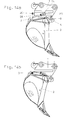
- FIGS. 6 and 7 show another embodiment a locking bolt 15, namely FIGS. 6 and 7 on Example of an actuable by means of a hydraulic cylinder 11 Riegel 4 and Fig. 13 using the example of one with a Spindle 20 operable bolt 4 of a quick-change device 1.
- Fig. 6 shows the locking pin 15 in its unlocked position (also Fig. 13 and 14) and Fig. 7 the securing bolt 15 in its the movement of the bolt 4 blocking operative position.
- Embodiment is the locking bolt 15 by a compression coil spring 25 in its operative position shown in FIG. 7 loaded, the compression coil spring 25 in one on the side wall 9 of the box-shaped receiving space the locking device 1 screwed housing 26 added is.
- a handle 27 which one facing inward Pin 28 carries.
- an operator attracts the handle 27 and rotates it so that the pin 28 on a console 21 of an attachment 2 rests (position according to 6 and 13).
- the quick-change device 1 In this position of the securing bolt 15 can the quick-change device 1 either by pressing of the locking cylinder 11 or the adjusting spindle 20 opened and the attachment 2 from the quick-change device 1 be removed. As soon as this is done, the spring presses 25 the locking bolt 15 in contact with the side surface of the bolt 4, with the free end of the pin 28 just next to the outside of the side wall 9 of the box-shaped receiving space the locking device 1 comes to rest.
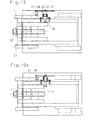
- 15 and 16 is for a quick-change device 1 similar to that of Figs. 3 to 5 shown that the inventive Quick-change device 1 a locking control, a visual inspection of the position of the bolt 4 allowed, can be provided.
- 17 and 18 show this for a quick change device 1 with adjustment of the bolt 4 by the screw spindle 20.
- an indicator 30 is provided which is in line with the rear one End 14 of the bolt 4 is connected and as described above indicates the position of the bolt 4, so that a visual inspection the locked or unlocked position of the lock constantly, even from the cab of the excavator.
- the part of the indicator can be used to improve the visual inspection 30, the unlocked position of the bolt 4 from the Recording space of the quick-change device 1 protrudes in the signal color be painted so that it indicates "danger".
- the operative position of the bolt 4 only visible end surface 31 of the indicator 30 is preferably the same Colored like the quick-change device so that "No danger” is displayed and the correct locking between quick-change device 1 and attachment 2 is.
- the bolt 4 of the quick-change device 1 is by the Hydraulic cylinder 11 moved forward or backward.
- the advanced one (Extended) position of the cylinder 11 corresponds to that advanced, engaging in the receptacle 3 of the attachment 2 Bolt 4 of the quick-change device 1.
- the check valve 42 and the pressure reducing valve 41 are in a common valve block 40 included.
- Preload valve 45 installed, which only at a pressure of 80 bar opens.
- Two 3/2 way ball valves 43 and 46 are used to shut off the Hydraulic system, furthermore these 3/2 way valves 43 and 46 other hydraulic via the same hydraulic circuit controlled work equipment.
- an indicator shown in FIG. 20 30 this is designed as a round rod, which is in a sleeve 50 is led.
- the sleeve 50 is on the quick-change device attached so that the free end 31 of the indicator 30, so as shown in Fig. 18, for example is coming.
- Fig. 20 it is also shown that the interior of the Rifle in the area where the indicator 30 is on its side wall 32 is colored or painted with signal color, is set off, so that signal color when moving the indicator 30 is not damaged.
- a collar 52 is fastened via a screw 51, against which a compression coil spring 53 abuts, with their other end abuts a shoulder 54 in the sleeve 50.
- the bolt 4 of the quick-change device is one Bolted round rod 55, the 4 on the screw 51 of the indicator 30 and this in Fig. 20 moves to the left so that the free end of the indicator 30 and its area 32 painted with signal color is visible and, as before, for the other embodiments of the safety display device, indicates that the quick-change device is unlocked.
- a quick-change device 1 via which an attachment on The boom of an excavator can be attached in one provided in the quick-change device 1, box-shaped Guided recording room, a bolt 4, which in the locked position in a correspondingly shaped receptacle engages on the attachment.
- a hydraulic cylinder 11 is provided be, the piston rod coupled to the bolt 4 is.
- the bolt 4 can also be moved forward and backward by means of an adjusting spindle be pushed back.
- a safety bolt 15 provided that in its operative position against the Back 14 of the bolt 4 abuts and prevents this be pushed back into the quick-change device 1 can.
- a hydraulic cylinder is used to actuate the securing bolt 15 16 provided, the piston rod preferably immediately forms the securing bolt 15.
- the piston in the Hydraulic cylinder 16 is spring-loaded so that when depressurized Cylinder 16 of the locking pin 15 in its operative position is advanced. This ensures that if there is a drop in pressure in the hydraulic system of the safety bolts 15 in any case its active action is postponed.
- the latch 4 may be assigned a display device 30 which with bolt 4 advanced into its operative position the quick-change device 1 is included and the in its non-operative position retracted bolt 4 from the Quick-change device 1 protrudes.
Landscapes
- Engineering & Computer Science (AREA)
- Mechanical Engineering (AREA)
- Mining & Mineral Resources (AREA)
- Civil Engineering (AREA)
- General Engineering & Computer Science (AREA)
- Structural Engineering (AREA)
- Shovels (AREA)
Abstract
Claims (22)
- Dispositif à échange rapide (1) permettant de fixer des outils portés (2) sur des flèches d'excavateur, comprenant un verrou (4) pouvant être déplacé dans le dispositif à échange rapide (1) et introduit dans le creux de réception (3) de l'outil porté (2) pour coupler celui-ci au dispositif à échange rapide (1), dans lequel est prévu un élément de sécurité (15) qui peut être déplacé, transversalement à la direction de déplacement du verrou (4), dans ou hors de sa position active, dans laquelle il empêche le déplacement du verrou (4) hors du creux de réception (3) de l'outil porté (2), caractérisé en ce que l'élément de sécurité est une cheville de sûreté (15), que celle-ci passe à travers un trou dans une paroi (7, 8, 9, 10) d'un espace de réception, qui sert de guide au verrou (4) et qui est disposé dans le dispositif à échange rapide (1), en ce qu'à verrou déplacé en avant, hors du dispositif à échange rapide (1), la cheville de sûreté (15) est disposée à côté de l'extrémité (14) du verrou (4) se trouvant à l'intérieur du dispositif à échange rapide (1) ou s'appuie contre l'extrémité (14) et que l'extrémité avant de la cheville de sûreté (15), à verrou (4) déplacé en arrière, est disposée à côté d'une des faces latérales du verrou (4).
- Dispositif selon la revendication 1, caractérisé en ce qu'un moteur linéaire (16) est prévu pour déplacer la cheville de sûreté (15).
- Dispositif selon la revendication 2, caractérisé en ce que le moteur linéaire est un vérin hydraulique (16).
- Dispositif selon la revendication 3, caractérisé en ce que le piston du vérin hydraulique (16) est à ressort dans le sens de déplacement en avant, dans sa position active, de la cheville de sûreté (15).
- Dispositif selon revendication 3 ou 4, caractérisé en ce que le piston du vérin hydraulique (16) est la cheville de sûreté (15).
- Dispositif selon la revendication 1, caractérisé en ce qu'à la cheville de sûreté (15) est reliée une commande de manipulation (27), par l'intermédiaire de laquelle, la cheville de sûreté (15) peut être déplacée dans et hors de sa position active.
- Dispositif selon la revendication 6, caractérisé en ce qu'à la cheville de sûreté (15) est associée une vis à pression à ressort (25), qui charge la cheville de sûreté (15) dans le sens d'un déplacement dans sa position active.
- Dispositif selon les revendications 6 ou 7, caractérisé en ce qu'un bouton (28) prévu sur la commande de manipulation (27), vient s'appuyer, après avoir tourné la commande de manipulation (27), contre un composant (27) du dispositif à échange rapide (1) ou contre l'outil porté (2), où il maintient la cheville de sûreté (15) dans sa position inactive déplacée en arrière.
- Dispositif selon la revendication 1, caractérisé en ce qu'une patte (36), par l'intermédiaire de laquelle la cheville de sûreté (15) peut être arrêtée dans sa position active, est reliée à celle-ci.
- Dispositif selon la revendication 9, caractérisé en ce qu'un trou (17) est prévu dans la patte (36), à travers lequel fait saillie une tige (18) fixée sur la face extérieure d'une des parois (7 à 10) du creux de réception, quand la cheville de sûreté (15) est déplacée dans sa position active.
- Dispositif selon la revendication 10, caractérisé en ce qu'à l'extrémité libre de la tige (18) est prévu un trou transversal, à travers lequel peut être passée une cheville de retenue, par exemple une dent escamotable ou une goupille pour fixer la patte (36).
- Dispositif selon une des revendications 3 à 5, caractérisé en ce que le vérin hydraulique (16), qui est associé à la cheville de sûreté (15) est alimenté en milieu hydraulique par une conduite dérivée de celle, par laquelle le vérin (11) servant au déplacement du verrou (4) est alimenté en milieu hydraulique dans le sens du déplacement en arrière du verrou (4).
- Dispositif (1) servant à fixer des outils portés (2) sur des flèches d'excavateurs comportant un verrou (4) pouvant être déplacé dans le dispositif à échange rapide (1) et pouvant être introduit dans un creux de réception (3) de l'outil porté (2), pour coupler l'outil porté (2) au dispositif à échange rapide (1),, ainsi qu'un dispositif indicateur (30), caractérisé en ce que celui-ci est fixé sur l'extrémité du verrou (4), se trouvant à l'intérieur du dispositif à échange rapide (1), et que le dispositif indicateur (30) se trouve à l'intérieur du dispositif à échange rapide (1), à verrou (4) déplacé en avant, dans sa position active, et qu'il fait saillie du dispositif à échange rapide (1), à verrou (4) déplacé en arrière, en position inactive.
- Dispositif (1) servant à fixer des outils portés (2) sur des flèches d'excavateurs comportant un verrou (4) pouvant être déplacé dans le dispositif à échange rapide (1) et introduit dans un creux de réception (3) de l'outil porté (2), pour coupler l'outil porté (2) au dispositif à échange rapide (1), ainsi qu'un dispositif indicateur (30), caractérisé en ce que le dispositif indicateur (30), à verrou (4) déplacé en avant, dans sa position active, se trouve à l'intérieur du dispositif à échange rapide (1) et fait saillie du dispositif à échange rapide (1), à verrou (4) déplacé en arrière, dans sa position inactive, en ce que le dispositif indicateur est un bâton guidé dans une fourrure (50) et qu'un bâton (55) relié au verrou (4) du dispositif à échange rapide (1) est associé à l'extrémité du dispositif indicateur(30) se trouvant à l'intérieur du dispositif à échange rapide (1).
- Dispositif selon la revendication 13, caractérisé en ce que le dispositif indicateur (30) est conçu en forme de bâton ou de baguette.
- Dispositif selon les revendications 14 ou 15, caractérisé en ce que le dispositif indicateur (30) en forme de bâton ou de baguette s'étend dans la direction de l'axe de déplacement du verrou (4).
- Dispositif selon une des revendications 13 à 16, caractérisé en ce que l'extrémité libre, en particulier, la face d'extrémité (31), tournée vers l'extérieur, du dispositif indicateur (30) est de la même couleur que le dispositif à échange rapide (1).
- Dispositif selon une des revendications 13 à 17, caractérisé en ce que les faces latérales (32) du dispositif indicateur (30) sont peintes dans une couleur contrastant avec celle du dispositif à échange rapide (1), notamment dans une couleur de signalisation.
- Dispositif selon une des revendications 13 à 18, caractérisé en ce que le dispositif indicateur (30), à verrou (4) déplacé en arrière, fait saillie du dispositif à échange rapide (1) sur le côté tourné vers la cabine de l'excavateur.
- Dispositif selon une des revendications 14 à 19, caractérisé en ce que le dispositif indicateur (30) se trouve sous l'effet d'un ressort (53), qui le charge dans sa position rentrée dans le dispositif à échange rapide (1).
- Dispositif selon une des revendications 14 à 20, caractérisé en ce que la fourrure (50) est écartée de la circonférence du dispositif indicateur (30) dans la zone de la section (32) du dispositif indicateur (30), qui est peinte dans une couleur de signalisation.
- Dispositif selon une des revendications 14 à 21, caractérisé en ce que la vis à pression à ressort (53) est serrée entre un collet (52) sur le dispositif indicateur (30) et un épaulement dans la fourrure (50).
Priority Applications (1)
| Application Number | Priority Date | Filing Date | Title |
|---|---|---|---|
| SI9830014T SI0975840T1 (en) | 1997-04-14 | 1998-04-09 | Device for attaching interchangeable items of equipment rapidly, for an excavator |
Applications Claiming Priority (5)
| Application Number | Priority Date | Filing Date | Title |
|---|---|---|---|
| AT22597U | 1997-04-14 | ||
| AT0022697U AT2088U1 (de) | 1997-04-14 | 1997-04-14 | Schnellwechselvorrichtung für bagger mit verriegelungssicherung |
| AT0022597U AT2087U1 (de) | 1997-04-14 | 1997-04-14 | Schnellwechselvorrichtung für bagger mit verriegelungsanzeige |
| AT22697U | 1997-04-14 | ||
| PCT/AT1998/000093 WO1998046835A1 (fr) | 1997-04-14 | 1998-04-09 | Dispositif de montage rapide pour pelle mecanique |
Publications (2)
| Publication Number | Publication Date |
|---|---|
| EP0975840A1 EP0975840A1 (fr) | 2000-02-02 |
| EP0975840B1 true EP0975840B1 (fr) | 2001-03-07 |
Family
ID=25591937
Family Applications (1)
| Application Number | Title | Priority Date | Filing Date |
|---|---|---|---|
| EP98914694A Expired - Lifetime EP0975840B1 (fr) | 1997-04-14 | 1998-04-09 | Dispositif de montage rapide pour pelle mecanique |
Country Status (4)
| Country | Link |
|---|---|
| EP (1) | EP0975840B1 (fr) |
| AU (1) | AU6910498A (fr) |
| DE (1) | DE59800510D1 (fr) |
| WO (1) | WO1998046835A1 (fr) |
Cited By (1)
| Publication number | Priority date | Publication date | Assignee | Title |
|---|---|---|---|---|
| DE102015225498A1 (de) | 2015-12-16 | 2017-06-22 | Oilquick Deutschland Gmbh | Schnellwechselsystem mit mechanischer sicherheitseinrichtung gegen unbeabsichtigtes ablösen eines arbeitsgerätes |
Families Citing this family (20)
| Publication number | Priority date | Publication date | Assignee | Title |
|---|---|---|---|---|
| FR2785952B1 (fr) | 1998-11-12 | 2001-04-06 | Alain Husson | Attache rapide pour fixer un outil a l'extremite du bras d'un chargeur ou analogue |
| AU5310000A (en) * | 1999-06-08 | 2000-12-28 | Up-Right Inc. | Device for coupling an implement to a telescopic boom type vehicle |
| IT1319865B1 (it) * | 2000-03-27 | 2003-11-03 | C M S N C Di Cangini Giorgio & | Dispositivo per l'aggancio e lo sgancio rapido dell'attrezzo di scavonegli escavatori idraulici. |
| FR2809779B1 (fr) * | 2000-05-31 | 2002-07-19 | Alain Husson | Dispositif de securite pour attache rapide destinee a fixer un outil a l'extremite du bras d'un chargeur ou analogue |
| AT413117B (de) * | 2003-04-24 | 2005-11-15 | Baumaschinentechnik Ges M B H | Anbauplatte für schnellwechselvorrichtung |
| FR2854415B1 (fr) * | 2003-04-30 | 2005-07-08 | Const Du Beaujolais Atel | Dispositif securise de verrouillage hydraulique d'attaches rapides et de connexions hydrauliques associees, entre le coupleur d'un bras porteur d'un engin et un outil |
| AT8623U3 (de) | 2006-03-27 | 2007-04-15 | Baumaschinentechnik Ges M B H | Vorrichtung zum befestigen von anbaugeräten |
| AT9344U1 (de) | 2006-03-27 | 2007-08-15 | Baumaschinentechnik Ges M B H | Anbauplatte für eine schnellwechselvorrichtung |
| CA2590464A1 (fr) | 2007-05-30 | 2008-11-30 | Brandt Industries Ltd. | Mecanisme a raccord rapide pour fixation d'outil |
| AT507598B1 (de) * | 2008-12-05 | 2012-03-15 | Wacker Neuson Linz Gmbh | Vorrichtung zum auswechselbaren aufnehmen von werkzeugen |
| AT11312U1 (de) | 2009-03-23 | 2010-08-15 | Baumaschinentechnik Ges M B H | Schnellkupplung für baumaschinen |
| AT508631A1 (de) | 2009-08-21 | 2011-03-15 | Perwein Baumaschinen Systeme Gmbh | Kupplungsvorrichtung |
| AT510095B1 (de) * | 2010-07-06 | 2012-06-15 | Erna Kronberger | Insektenschutzvorrichtung |
| EP2931981A4 (fr) * | 2012-12-10 | 2016-11-02 | Wedgelock Equipment Ltd | Mécanisme de verrouillage |
| ITBO20130410A1 (it) * | 2013-07-29 | 2015-01-30 | Cangini Benne Srl | Dispositivo di connessione di un utensile ad un braccio di azionamento |
| DE102014116245B4 (de) * | 2014-11-07 | 2016-11-10 | Bela Cseri | Schnellwechseleinrichtung einer Arbeitsmaschine |
| AT515695B1 (de) | 2014-11-20 | 2015-11-15 | Baumaschinentechnik Ges M B H | Kupplung für Baumaschinen |
| AT15516U1 (de) | 2016-07-14 | 2017-11-15 | Baumaschinentechnik Ges M B H | Kupplung für Baumaschinen |
| DE102017110586B4 (de) | 2017-05-16 | 2023-03-23 | OilQuick Deutschland KG | Schnellwechsler und Schnellwechselsystem mit einem derartigen Schnellwechsler |
| DE102023127568A1 (de) * | 2023-10-10 | 2025-04-10 | OilQuick Deutschland KG | Schnellwechselsystem und adapter für ein derartiges schnellwechselsystem |
Family Cites Families (7)
| Publication number | Priority date | Publication date | Assignee | Title |
|---|---|---|---|---|
| US3985249A (en) * | 1975-04-14 | 1976-10-12 | International Harvester Company | Quick change attachment |
| US4436477A (en) * | 1982-03-25 | 1984-03-13 | Farmhand, Inc. | Quick attachment carrier assembly |
| US5010962A (en) * | 1990-04-30 | 1991-04-30 | Caterpillar Inc. | Indicating apparatus for a coupling |
| GB9107596D0 (en) * | 1991-04-10 | 1991-05-29 | Dunbar Ian S | A mounting assembly for a digging bucket |
| DE4410194A1 (de) * | 1994-03-24 | 1995-10-05 | Karl Heinz Josef Leh | Am Auslegerarm eines Bodenbearbeitungswerkzeuges, Baggers o. dgl. befestigbare Aufnahme- und Befestigungsvorrichtung für ein Werkzeug, einen Baggerlöffel o. dgl. |
| US5467542A (en) * | 1994-08-23 | 1995-11-21 | Hulden; Fritiof | Coupling assembly and actuating mechanism therefor |
| US5634735A (en) * | 1995-06-07 | 1997-06-03 | Wain-Roy, Inc. | Tool coupler |
-
1998
- 1998-04-09 DE DE59800510T patent/DE59800510D1/de not_active Expired - Lifetime
- 1998-04-09 WO PCT/AT1998/000093 patent/WO1998046835A1/fr not_active Ceased
- 1998-04-09 EP EP98914694A patent/EP0975840B1/fr not_active Expired - Lifetime
- 1998-04-09 AU AU69104/98A patent/AU6910498A/en not_active Abandoned
Cited By (1)
| Publication number | Priority date | Publication date | Assignee | Title |
|---|---|---|---|---|
| DE102015225498A1 (de) | 2015-12-16 | 2017-06-22 | Oilquick Deutschland Gmbh | Schnellwechselsystem mit mechanischer sicherheitseinrichtung gegen unbeabsichtigtes ablösen eines arbeitsgerätes |
Also Published As
| Publication number | Publication date |
|---|---|
| EP0975840A1 (fr) | 2000-02-02 |
| AU6910498A (en) | 1998-11-11 |
| WO1998046835A1 (fr) | 1998-10-22 |
| DE59800510D1 (de) | 2001-04-12 |
Similar Documents
| Publication | Publication Date | Title |
|---|---|---|
| EP0975840B1 (fr) | Dispositif de montage rapide pour pelle mecanique | |
| DE60215289T2 (de) | Werkzeugschnellkupplung zum Kuppeln eines Anbauteils an einen Baggerarm und die Werkzeugschnellkupplung umfassend ein Steuerungssystem | |
| DE102004045663B4 (de) | Verschiebevorrichtung für eine Sattelkupplung | |
| EP3591122B1 (fr) | Système de changement rapide | |
| DE69625440T2 (de) | Kupplungsanordnung für einen Bagger | |
| DE102018128479A1 (de) | Schnellwechsler und Schnellwechselsystem mit einem derartigen Schnellwechsler | |
| DE10221942A1 (de) | Vorrichtung zum Festlegen eines Werkzeugs an einem Hubwerk | |
| EP3266940B1 (fr) | Raccord rapide | |
| DE202021100754U1 (de) | Schnellwechsler und Schnellwechselvorrichtung mit einem Schnellwechsler | |
| DE202021101016U1 (de) | Schnellwechsler für Baumaschinenwerkzeuge | |
| AT2322U2 (de) | Schnellwechselvorrichtung für bagger mit verriegelungssicherung | |
| AT2087U1 (de) | Schnellwechselvorrichtung für bagger mit verriegelungsanzeige | |
| DE3322551A1 (de) | Adapter zum ausschalten der seitenbeweglichkeit von unterlenkern eines ackerschleppers | |
| EP3770330B1 (fr) | Dispositif de changement rapide | |
| EP4310260B1 (fr) | Dispositif de changement rapide et système de changement rapide doté d'un tel dispositif de changement rapide | |
| AT2088U1 (de) | Schnellwechselvorrichtung für bagger mit verriegelungssicherung | |
| DE102012002122A1 (de) | Verriegelungsvorrichtung für einen Teleskopausleger | |
| AT411075B (de) | Schnellwechselvorrichtung für bagger | |
| DE2856039C2 (de) | Kupplungsvorrichtung zum Anbringen eines Arbeitsgeräts am Ausleger eines Fahrzeugs | |
| DE3512981A1 (de) | Kupplungswechselrahmen | |
| DE102016014905B3 (de) | Werkzeugadapter mit einer Vorrichtung zur Verriegelungskontrolle einer Schnellwechselvorrichtung für Baugeräte | |
| DE102015225498A1 (de) | Schnellwechselsystem mit mechanischer sicherheitseinrichtung gegen unbeabsichtigtes ablösen eines arbeitsgerätes | |
| EP4229243B1 (fr) | Dispositif à changement rapide pourvu d'un dispositif de commande doté d'une soupape à commande mécanique et hydraulique | |
| DE102006049059A1 (de) | Hydraulischer Schnellwechsler | |
| DE20215590U1 (de) | Schnellkupplung zum Befestigen von Arbeitswerkzeugen an einem Baggerausleger |
Legal Events
| Date | Code | Title | Description |
|---|---|---|---|
| PUAI | Public reference made under article 153(3) epc to a published international application that has entered the european phase |
Free format text: ORIGINAL CODE: 0009012 |
|
| 17P | Request for examination filed |
Effective date: 19991013 |
|
| AK | Designated contracting states |
Kind code of ref document: A1 Designated state(s): DE FR IT |
|
| AX | Request for extension of the european patent |
Free format text: SI PAYMENT 19991013 |
|
| GRAG | Despatch of communication of intention to grant |
Free format text: ORIGINAL CODE: EPIDOS AGRA |
|
| 17Q | First examination report despatched |
Effective date: 20000626 |
|
| GRAG | Despatch of communication of intention to grant |
Free format text: ORIGINAL CODE: EPIDOS AGRA |
|
| GRAH | Despatch of communication of intention to grant a patent |
Free format text: ORIGINAL CODE: EPIDOS IGRA |
|
| GRAH | Despatch of communication of intention to grant a patent |
Free format text: ORIGINAL CODE: EPIDOS IGRA |
|
| GRAA | (expected) grant |
Free format text: ORIGINAL CODE: 0009210 |
|
| AK | Designated contracting states |
Kind code of ref document: B1 Designated state(s): DE FR IT |
|
| AX | Request for extension of the european patent |
Free format text: SI PAYMENT 19991013 |
|
| ET | Fr: translation filed | ||
| REF | Corresponds to: |
Ref document number: 59800510 Country of ref document: DE Date of ref document: 20010412 |
|
| ITF | It: translation for a ep patent filed | ||
| PLBE | No opposition filed within time limit |
Free format text: ORIGINAL CODE: 0009261 |
|
| STAA | Information on the status of an ep patent application or granted ep patent |
Free format text: STATUS: NO OPPOSITION FILED WITHIN TIME LIMIT |
|
| 26N | No opposition filed | ||
| REG | Reference to a national code |
Ref country code: SI Ref legal event code: IF |
|
| PGFP | Annual fee paid to national office [announced via postgrant information from national office to epo] |
Ref country code: FR Payment date: 20120525 Year of fee payment: 15 |
|
| PGFP | Annual fee paid to national office [announced via postgrant information from national office to epo] |
Ref country code: IT Payment date: 20120426 Year of fee payment: 15 |
|
| PGFP | Annual fee paid to national office [announced via postgrant information from national office to epo] |
Ref country code: DE Payment date: 20130416 Year of fee payment: 16 |
|
| REG | Reference to a national code |
Ref country code: FR Ref legal event code: ST Effective date: 20131231 Ref country code: SI Ref legal event code: KO00 Effective date: 20131231 |
|
| PG25 | Lapsed in a contracting state [announced via postgrant information from national office to epo] |
Ref country code: IT Free format text: LAPSE BECAUSE OF NON-PAYMENT OF DUE FEES Effective date: 20130409 Ref country code: FR Free format text: LAPSE BECAUSE OF NON-PAYMENT OF DUE FEES Effective date: 20130430 |
|
| REG | Reference to a national code |
Ref country code: DE Ref legal event code: R119 Ref document number: 59800510 Country of ref document: DE |
|
| PG25 | Lapsed in a contracting state [announced via postgrant information from national office to epo] |
Ref country code: DE Free format text: LAPSE BECAUSE OF NON-PAYMENT OF DUE FEES Effective date: 20141101 |
|
| REG | Reference to a national code |
Ref country code: DE Ref legal event code: R119 Ref document number: 59800510 Country of ref document: DE Effective date: 20141101 |