EP0975925B1 - Brenngutträger - Google Patents
Brenngutträger Download PDFInfo
- Publication number
- EP0975925B1 EP0975925B1 EP98912364A EP98912364A EP0975925B1 EP 0975925 B1 EP0975925 B1 EP 0975925B1 EP 98912364 A EP98912364 A EP 98912364A EP 98912364 A EP98912364 A EP 98912364A EP 0975925 B1 EP0975925 B1 EP 0975925B1
- Authority
- EP
- European Patent Office
- Prior art keywords
- carrier
- support
- baked according
- baked
- support beams
- Prior art date
- Legal status (The legal status is an assumption and is not a legal conclusion. Google has not performed a legal analysis and makes no representation as to the accuracy of the status listed.)
- Expired - Lifetime
Links
- 239000000463 material Substances 0.000 title claims abstract description 28
- 239000002826 coolant Substances 0.000 claims abstract description 17
- 239000000919 ceramic Substances 0.000 claims abstract description 11
- 239000002184 metal Substances 0.000 claims abstract 2
- 238000010304 firing Methods 0.000 claims description 17
- 229910000831 Steel Inorganic materials 0.000 claims description 3
- 238000005192 partition Methods 0.000 claims description 3
- 239000010959 steel Substances 0.000 claims description 3
- 239000000725 suspension Substances 0.000 claims description 3
- 230000008878 coupling Effects 0.000 claims 1
- 238000010168 coupling process Methods 0.000 claims 1
- 238000005859 coupling reaction Methods 0.000 claims 1
- 238000009422 external insulation Methods 0.000 claims 1
- 238000007373 indentation Methods 0.000 claims 1
- HBMJWWWQQXIZIP-UHFFFAOYSA-N silicon carbide Chemical compound [Si+]#[C-] HBMJWWWQQXIZIP-UHFFFAOYSA-N 0.000 claims 1
- 229910010271 silicon carbide Inorganic materials 0.000 claims 1
- 238000002485 combustion reaction Methods 0.000 description 12
- 238000001816 cooling Methods 0.000 description 3
- 229910010293 ceramic material Inorganic materials 0.000 description 2
- 238000010438 heat treatment Methods 0.000 description 2
- 238000009413 insulation Methods 0.000 description 2
- XLYOFNOQVPJJNP-UHFFFAOYSA-N water Substances O XLYOFNOQVPJJNP-UHFFFAOYSA-N 0.000 description 2
- 239000011449 brick Substances 0.000 description 1
- 239000004927 clay Substances 0.000 description 1
- 238000007872 degassing Methods 0.000 description 1
- 238000001035 drying Methods 0.000 description 1
- 230000000694 effects Effects 0.000 description 1
- 238000001704 evaporation Methods 0.000 description 1
- 230000008020 evaporation Effects 0.000 description 1
- 239000002737 fuel gas Substances 0.000 description 1
- 230000017525 heat dissipation Effects 0.000 description 1
- 238000004519 manufacturing process Methods 0.000 description 1
- 238000003032 molecular docking Methods 0.000 description 1
- 238000000465 moulding Methods 0.000 description 1
- 230000035939 shock Effects 0.000 description 1
- 230000008646 thermal stress Effects 0.000 description 1
Images




Classifications
-
- F—MECHANICAL ENGINEERING; LIGHTING; HEATING; WEAPONS; BLASTING
- F27—FURNACES; KILNS; OVENS; RETORTS
- F27D—DETAILS OR ACCESSORIES OF FURNACES, KILNS, OVENS OR RETORTS, IN SO FAR AS THEY ARE OF KINDS OCCURRING IN MORE THAN ONE KIND OF FURNACE
- F27D9/00—Cooling of furnaces or of charges therein
-
- F—MECHANICAL ENGINEERING; LIGHTING; HEATING; WEAPONS; BLASTING
- F27—FURNACES; KILNS; OVENS; RETORTS
- F27B—FURNACES, KILNS, OVENS OR RETORTS IN GENERAL; OPEN SINTERING OR LIKE APPARATUS
- F27B9/00—Furnaces through which the charge is moved mechanically, e.g. of tunnel type; Similar furnaces in which the charge moves by gravity
- F27B9/14—Furnaces through which the charge is moved mechanically, e.g. of tunnel type; Similar furnaces in which the charge moves by gravity characterised by the path of the charge during treatment; characterised by the means by which the charge is moved during treatment
- F27B9/20—Furnaces through which the charge is moved mechanically, e.g. of tunnel type; Similar furnaces in which the charge moves by gravity characterised by the path of the charge during treatment; characterised by the means by which the charge is moved during treatment the charge moving in a substantially straight path
- F27B9/26—Furnaces through which the charge is moved mechanically, e.g. of tunnel type; Similar furnaces in which the charge moves by gravity characterised by the path of the charge during treatment; characterised by the means by which the charge is moved during treatment the charge moving in a substantially straight path on or in trucks, sleds, or containers
- F27B9/262—Furnaces through which the charge is moved mechanically, e.g. of tunnel type; Similar furnaces in which the charge moves by gravity characterised by the path of the charge during treatment; characterised by the means by which the charge is moved during treatment the charge moving in a substantially straight path on or in trucks, sleds, or containers on or in trucks
-
- F—MECHANICAL ENGINEERING; LIGHTING; HEATING; WEAPONS; BLASTING
- F27—FURNACES; KILNS; OVENS; RETORTS
- F27D—DETAILS OR ACCESSORIES OF FURNACES, KILNS, OVENS OR RETORTS, IN SO FAR AS THEY ARE OF KINDS OCCURRING IN MORE THAN ONE KIND OF FURNACE
- F27D3/00—Charging; Discharging; Manipulation of charge
- F27D3/12—Travelling or movable supports or containers for the charge
- F27D3/123—Furnace cars
-
- F—MECHANICAL ENGINEERING; LIGHTING; HEATING; WEAPONS; BLASTING
- F27—FURNACES; KILNS; OVENS; RETORTS
- F27D—DETAILS OR ACCESSORIES OF FURNACES, KILNS, OVENS OR RETORTS, IN SO FAR AS THEY ARE OF KINDS OCCURRING IN MORE THAN ONE KIND OF FURNACE
- F27D5/00—Supports, screens or the like for the charge within the furnace
- F27D5/0006—Composite supporting structures
-
- F—MECHANICAL ENGINEERING; LIGHTING; HEATING; WEAPONS; BLASTING
- F27—FURNACES; KILNS; OVENS; RETORTS
- F27B—FURNACES, KILNS, OVENS OR RETORTS IN GENERAL; OPEN SINTERING OR LIKE APPARATUS
- F27B9/00—Furnaces through which the charge is moved mechanically, e.g. of tunnel type; Similar furnaces in which the charge moves by gravity
- F27B9/14—Furnaces through which the charge is moved mechanically, e.g. of tunnel type; Similar furnaces in which the charge moves by gravity characterised by the path of the charge during treatment; characterised by the means by which the charge is moved during treatment
- F27B9/20—Furnaces through which the charge is moved mechanically, e.g. of tunnel type; Similar furnaces in which the charge moves by gravity characterised by the path of the charge during treatment; characterised by the means by which the charge is moved during treatment the charge moving in a substantially straight path
- F27B9/26—Furnaces through which the charge is moved mechanically, e.g. of tunnel type; Similar furnaces in which the charge moves by gravity characterised by the path of the charge during treatment; characterised by the means by which the charge is moved during treatment the charge moving in a substantially straight path on or in trucks, sleds, or containers
- F27B9/262—Furnaces through which the charge is moved mechanically, e.g. of tunnel type; Similar furnaces in which the charge moves by gravity characterised by the path of the charge during treatment; characterised by the means by which the charge is moved during treatment the charge moving in a substantially straight path on or in trucks, sleds, or containers on or in trucks
- F27B2009/266—Furnaces through which the charge is moved mechanically, e.g. of tunnel type; Similar furnaces in which the charge moves by gravity characterised by the path of the charge during treatment; characterised by the means by which the charge is moved during treatment the charge moving in a substantially straight path on or in trucks, sleds, or containers on or in trucks the truck having conducts for guiding the oven atmosphere
- F27B2009/268—Furnaces through which the charge is moved mechanically, e.g. of tunnel type; Similar furnaces in which the charge moves by gravity characterised by the path of the charge during treatment; characterised by the means by which the charge is moved during treatment the charge moving in a substantially straight path on or in trucks, sleds, or containers on or in trucks the truck having conducts for guiding the oven atmosphere through the structure of the car and through the charge
-
- F—MECHANICAL ENGINEERING; LIGHTING; HEATING; WEAPONS; BLASTING
- F27—FURNACES; KILNS; OVENS; RETORTS
- F27D—DETAILS OR ACCESSORIES OF FURNACES, KILNS, OVENS OR RETORTS, IN SO FAR AS THEY ARE OF KINDS OCCURRING IN MORE THAN ONE KIND OF FURNACE
- F27D3/00—Charging; Discharging; Manipulation of charge
- F27D2003/0085—Movement of the container or support of the charge in the furnace or in the charging facilities
- F27D2003/0087—Rotation about a vertical axis
Definitions
- the invention relates to a firing tray for ceramic Material according to the preamble of claim 1.
- a firing tray of the known type (DE 40 16 227 A1) are provided on a kiln car, ceramic support rods on which brick moldings in several Floors are arranged in the air-washed trim.
- the support rods rest on ceramic support elements that are sensitive to shock, as well as inelastic and take up a lot of space to have.
- Another firing tray of this type (EP 0 208 249 A) has only ceramic components Support elements on which the disadvantages of have ceramic designs.
- the invention has for its object a Brennguta to create the shockproof and elastic trained and is inexpensive to manufacture.
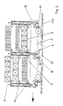
- a combustion car 1 is located in a combustion chamber 14 of a furnace 21 guided longitudinally on rails 21a.
- the kiln car 1 consists of a vehicle frame 5 with wheels 5a, the through an insulating cover 2 from the high temperatures of the combustion chamber 14 is protected.
- On the vehicle frame 5 are attached to both long sides sliding plates 5b, the in connection with counter plates 21b the bottom area 14c of the Separate the combustion chamber 14 from the rest of the combustion chamber 14.
- On the Carriage frame 5 rest vertical supports 4, on which in several Floors cross member 8 are attached, in which support rods 7 are stored.
- the ceramic support rods 7 take that Firing material 3 in such a way that there is air on all sides and / or Fuel gases can be washed around.
- a coolant supply line is in the protected floor area 14c 13 housed, in which a nozzle 12 protrudes.
- the nozzle 12 is with a distribution line 11 in the car frame 5 connected, the the gaseous coolant the hollow Supports 4 in which it is due to the chimney effect flows upwards and at the upper open end into the combustion chamber 14 exits.
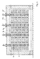
- FIG. 2 shows a kiln car 1 in longitudinal section, which is movable on rails 21a.
- three supports 4 are attached one behind the other, between which Support rods 7 rest on brackets 6. With the help of the consoles 6, the distance between the support rods 7 of the height of the firing material 3 can be adjusted.
- the supports 4 are of one Outside insulation 9 surrounded.
- Each transverse row of supports 4 is supplied with coolant through a distributor line 11, which is connected to the interior of the support 4 and a connector 12 for docking to a coolant supply line 13 has. As indicated by the arrows in Fig. 2, the coolant occurs on the supports 4 in the Combustion chamber 14 out.
- the cavity of the support 4 ' as shown in FIGS. 3a and 3b, by a Longitudinal partition 10 divided into two cooling channels 10a, 10b of which the one channel 10b as a return line serves.
- the support 4 ' is on the top 4b' locked. Between the top 4b 'and the Longitudinal partition wall 10 remains a gap that the cooling channels 10a, 10b connects together. Part of the coolant get into the combustion chamber 14, a correspondingly dimensioned Opening 15 at the top 4b 'of the support 4 'are provided.
- Brackets 6 are attached to the support 4 '(FIG. 3b) penetrate the outer insulation 9. Wear the consoles 6 Cross member 8, in which parallel support rods, not shown run across.
- Fig. 4 is a hanging arrangement of the Brenngut lacking shown.
- Each suspension device 16 can be one Wear support 4.
- the connector 12 ' is coupled to the support 4.
- the support rods 7 are fastened to the supports 4, on which the kiln 3 rests. The firing and drying process can be improved if the firing tray supports the Longitudinal axes 4a of the supports 4 are rotatable.
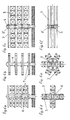
- FIG. 6a shows different arrangements the support rods 7 on a support 4.
- Cross in Fig. 6a two horizontal ones arranged parallel to each other Support rods 7 at a right angle and enclose the Support 4, as seen from the plan view shown in Fig. 6d 6a can be seen.
- Fig. 6b there are three pairs in parallel on each floor Support rods 7 arranged. As shown in Fig. 6e Top view of Fig. 6b can be seen, are in pairs parallel support rods 7 to the neighboring Pairs arranged at a 60 degree angle.
- the support 4 has a square Cross-section.
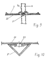
- the ceramic support rod 7 ' has a trapezoidal shape Hollow profile with a wider contact area 7a.
- the support rod 7 ' rests with its two side surfaces 7b, 7c in a recording 17. By the inclination of the Side surfaces 7b, 7c and the counter surfaces of the receptacle 17 the support rod 7 'is centered.
- On the support area 7a the kiln 3 is placed.
- To improve water evaporation or degassing is the support area 7a a groove-like recess 7d.
- FIG. 8 The attachment of a triangular support rod 7 "to one Support 4 shows FIG. 8.
- a cross member 8 is on support 4 attached, the triangular receptacles 17 'on its top having.
- Two mutually parallel support rods 7 "through an abutment 20 is held in the receptacle 17 '.
Landscapes
- Engineering & Computer Science (AREA)
- Mechanical Engineering (AREA)
- General Engineering & Computer Science (AREA)
- Furnace Charging Or Discharging (AREA)
- Heat Treatments In General, Especially Conveying And Cooling (AREA)
- Furnace Details (AREA)
- Crystals, And After-Treatments Of Crystals (AREA)
- Fixed Capacitors And Capacitor Manufacturing Machines (AREA)
Description
Durch die Innenkühlung der Stützen werden tragfähige, elastische und gegen Temperaturschwankungen unempfindliche Materialien für die vertikalen Stützen verwendbar.
Es zeigen:
- Figur 1 -
- einen Ofenquerschnitt mit dem erfindungsgemä- ßen Brenngutträger auf einem Transportmittel;
- Figur 2 -
- einen Längsschnitt durch den Brenngutträger nach Fig. 1;
- Figur 3 -
- den Kopfteil einer Stütze im Längsschnitt;
- Figur 3a -
- einen Querschnitt der Stütze nach Fig. 3;
- Figur 4 -
- einen Ofenquerschnitt mit hängenden Brenngut trägern;
- Figur 5 -
- einen Ofenquerschnitt mit aufgeständerten Brenngutträgern;
- Figur 6a -
- einen Brenngutträger mit sich kreuzender Tragstabanordnung;
- Figur 6b -
- einen Brenngutträger mit sternförmiger Tragstabanordnung;
- Figur 6c -
- einen Brenngutträger mit paralleler Tragstabanordnung
- Figur 6d -
- eine Draufsicht auf den Brenngutträger nach Fig. 6a;
- Figur 6e -
- eine Draufsicht auf einen Brenngutträger nach Fig. 6b;
- Figur 6f -
- eine Draufsicht auf einen Brenngutträger nach Fig. 6c;
- Figur 7 -
- eine perspektivische Darstellung eines Tragstababschnitts mit Brenngut;
- Figur 8 -
- einen Abschnitt einer Stütze mit einem Tragstab und Quersprossen;
- Figur 9 -
- einen Abschnitt einer Stütze mit paarweiser Aufnahme der Tragstäbe;
- Figur 10 -
- einen Tragstab im Querschnitt mit offener Auflagefläche.
Claims (20)
- Brenngutträger für keramische Erzeugnisse mit mindestens einer vertikalen Stütze (4; 4') und an dieser befestigten, das Brenngut (3) tragenden, keramischen Tragstäben (7; 7';7"),
dadurch gekennzeichnet, daß die Stütze (4; 4') ein hohles, von einem gasförmigen Kühlmittel durchströmtes Metallprofil ist, welches eine Außenisolierung (9) aufweist. - Brenngutträger nach Anspruch 1,
dadurch gekennzeichnet, daß die Tragstäbe (7; 7'; 7") mindestens ein freies Ende aufweisen. - Brenngutträger nach Anspruch 1 oder 2,
dadurch gekennzeichnet, daß die Tragstäbe (7; 7'; 7") parallel zueinander an der Stütze (4; 4') befestigt sind. - Brenngutträger nach einem oder mehreren der Ansprüche 1 bis 3,
dadurch gekennzeichnet, daß die Tragstäbe (7; 7'; 7") die Stütze (4; 4') horizontal durchsetzen. - Brenngutträger nach einem oder mehreren der Ansprüche 1 bis 3,
dadurch gekennzeichnet, daß die Tragstäbe (7; 7'; 7") über Konsolen (6) an den Stützen (4, 4') befestigt sind. - Brenngutträger nach eienm oder mehreren der Ansprüche 1 bis 5,
dadurch gekennzeichnet, daß die keramischen Tragstäbe (7; 7'; 7") aus Siliciumcarbid bestehen. - Brenngutträger nach einem oder mehreren der Ansprüche 1 bis 6,
dadurch gekennzeichnet,
die Stütze (4; 4') aus hitzebeständigem Stahl besteht. - Brenngutträger nach einem oder mehreren der Ansprüch 1 bis 7,
dadurch gekennzeichnet, daß die Stütze (4; 4') über einen kuppelbaren Stutzen (12; 12') mit einer Kühlmittelzuleitung (13) verbunden ist. - Brenngutträger nach einem oder mehreren der Ansprüche 1 bis 8,
dadurch gekennzeichnet, daß die Stütze (4; 4') eine Öffnung (15) aufweist, über die das gasförmige Kühlmittel in den Brennraum (14) austritt. - Brenngutträger nach einem oder mehreren der Ansprüche 1 bis 9,
dadurch gekennzeichnet, daß die Stütze (4; 4') durch eine innere Längstrennwand (10) in zwei Kühlkanäle (10a; 10b) unterteilt ist, die am dem Kühlmitteleinlaß gegenüberliegenden Ende miteinander verbunden sind. - Brenngutträger nach einem oder mehreren der Ansprüche 1 bis 10,
dadurch gekennzeichnet, daß parallele Tragstäbe (7; 7'; 7") in mehreren Etagen übereinander an der Stütze (4; 4') befestigt sind. - Brenngutträger nach einem oder mehreren der Ansprüche 1 bis 11,
dadurch gekennzeichnet, daß die parallelen Tragstäbe (7; 7'; 7") einer Etage in der Draufsicht in Umfangsrichtung zueinander versetzt angeordnet sind. - Brenngutträger nach einem oder mehreren der Ansprüche 1 bis 12,
dadurch gekennzeichnet, daß die Stütze (4; 4') eine Aufhängevorrichtung (16) aufweist, mit der sie an einer Brennraumdecke (14a) befestigbar ist. - Brenngutträger nach einem oder mehreren der Ansprüche 1 bis 13,
dadurch gekennzeichnet, daß Stützen (4; 4') um ihre Längsachse (4a) drehbar gelagert sind. - Brenngutträger nach einem oder mehreren der Ansprüche 1 bis 14,
dadurch gekennzeichnet, daß die Tragstäbe (7') hohl sind. - Brenngutträger nach einem oder mehreren der Ansprüche 1 bis 15,
dadurch gekennzeichnet, daß die Tragstäbe (7'; 7") einen horizontalen Auflagebereich (7a) aufweisen und zwei einander gegenüberliegende Seitenflächen (7b; 7c) zueinander geneigt angeordnet sind, die an den Flanken einer zentrierenden, stützenfesten Aufnahme (17; 17') anliegen. - Brenngutträger nach Anspruch 16,
dadurch gekennzeichnet, daß der Querschnitt der Tragstäbe (7") dreieckig ist. - Brenngutträger nach Anspruch 16,
dadurch gekennzeichnet, daß der Querschnitt der Tragstäbe (7') trapezförmig ist. - Brenngutträger nach Anspruch 16,
dadurch gekennzeichnet, daß der horizontale Auflagebereich (7a) nutartige Vertiefungen (7d; 7d') aufweist. - Brenngutträger nach Anspruch 16,
dadurch gekennzeichnet, daß die Tragstäbe (7'; 7") durch Widerlager (20) in ihren Aufnahmen (17; 17') fixiert sind.
Applications Claiming Priority (7)
| Application Number | Priority Date | Filing Date | Title |
|---|---|---|---|
| DE19710045 | 1997-03-12 | ||
| DE1997110045 DE19710045A1 (de) | 1997-03-12 | 1997-03-12 | Brennwagenaufbau |
| DE19713562 | 1997-04-02 | ||
| DE1997113562 DE19713562A1 (de) | 1997-03-12 | 1997-04-02 | Brennwagenaufbau |
| DE29801681U DE29801681U1 (de) | 1998-02-02 | 1998-02-02 | Keramischer Brenngutträger |
| DE29801681U | 1998-02-02 | ||
| PCT/EP1998/001007 WO1998040682A1 (de) | 1997-03-12 | 1998-02-21 | Brenngutträger |
Publications (2)
| Publication Number | Publication Date |
|---|---|
| EP0975925A1 EP0975925A1 (de) | 2000-02-02 |
| EP0975925B1 true EP0975925B1 (de) | 2002-06-19 |
Family
ID=27217202
Family Applications (1)
| Application Number | Title | Priority Date | Filing Date |
|---|---|---|---|
| EP98912364A Expired - Lifetime EP0975925B1 (de) | 1997-03-12 | 1998-02-21 | Brenngutträger |
Country Status (5)
| Country | Link |
|---|---|
| EP (1) | EP0975925B1 (de) |
| AT (1) | ATE219571T1 (de) |
| DE (1) | DE59804517D1 (de) |
| ES (1) | ES2175694T3 (de) |
| WO (1) | WO1998040682A1 (de) |
Family Cites Families (9)
| Publication number | Priority date | Publication date | Assignee | Title |
|---|---|---|---|---|
| DE277757C (de) * | ||||
| DE279120C (de) * | ||||
| FR487611A (fr) * | 1917-11-15 | 1918-07-17 | George Hillard Benjamin | Four-tunnel à marche continue |
| GB433473A (en) * | 1934-02-19 | 1935-08-15 | Bernard Joseph Moore | Improvements in trucks |
| FR1337833A (fr) * | 1962-08-02 | 1963-09-20 | Fetok Gmbh | Perfectionnement aux fours-tunnels |
| GB2179127A (en) * | 1985-07-05 | 1987-02-25 | Acme Marls Ltd | Kiln cars |
| DE3605780C1 (en) * | 1986-02-22 | 1987-06-19 | Manfred Zimmermann | Tunnel furnace for baking raw graphite electrodes |
| DE3716532A1 (de) * | 1987-05-16 | 1988-12-08 | Didier Eng | Herdwagen fuer durchschuboefen |
| DE4008631C1 (en) * | 1990-03-17 | 1991-07-11 | Reining Heisskuehlung Gmbh & Co Kg, 4330 Muelheim, De | Furnace conveyor cooling method - has coolant fed to immersion troughs to cool conveyor trolley |
-
1998
- 1998-02-21 WO PCT/EP1998/001007 patent/WO1998040682A1/de not_active Ceased
- 1998-02-21 ES ES98912364T patent/ES2175694T3/es not_active Expired - Lifetime
- 1998-02-21 EP EP98912364A patent/EP0975925B1/de not_active Expired - Lifetime
- 1998-02-21 AT AT98912364T patent/ATE219571T1/de active
- 1998-02-21 DE DE59804517T patent/DE59804517D1/de not_active Expired - Lifetime
Also Published As
| Publication number | Publication date |
|---|---|
| DE59804517D1 (de) | 2002-07-25 |
| ES2175694T3 (es) | 2002-11-16 |
| EP0975925A1 (de) | 2000-02-02 |
| WO1998040682A1 (de) | 1998-09-17 |
| ATE219571T1 (de) | 2002-07-15 |
Similar Documents
| Publication | Publication Date | Title |
|---|---|---|
| DE3332592C1 (de) | Aus Rostelementen zusammengesetzter Rostboden fuer Schuettgueter,wie Zementklinker | |
| EP3355015B1 (de) | Tragelement für einen tunnelofenwagen oder -schlitten, tunnelofenwagen oder -schlitten mit derartigen tragelementen sowie tunnelofen mit einem derartigen tunnelofenwagen oder -schlitten | |
| DE3604501C1 (de) | Verfahren und Vorrichtung zur Unterwagenkuehlung von Ofenwagen in einem Tunnelofen | |
| DE2512485C3 (de) | Verfahren zum Brennen von keramischen Gegenständen im Brennraum eines intermittierenden Ofens und Brennofen zur Durchführung des Verfahrens | |
| EP0227927B2 (de) | Tunnelofen mit Unterwagenkühlung | |
| DE68911967T2 (de) | Verfahren zum Brennen von Keramik und dafür verwendetes Brennhilfsmittel. | |
| EP0975925A1 (de) | Brenngutträger | |
| DE10041132A1 (de) | Tunnelofenanlage zum Brennen von keramischen Formlingen, insbesondere Ziegeln | |
| DE2354672A1 (de) | Nach dem baukastenprinzip zusammenstellbares traggeruest aus feuerfestem baustoff zum brennen keramischer erzeugnisse, insbesondere fuer den einzelbrand glasierter formlinge | |
| DE2540401B2 (de) | Feuerfest in Sandwichbauweise zugestellter Tunnelofen | |
| DE69511277T2 (de) | Wärmedämmanordnung | |
| EP0002193A1 (de) | Brennhilfsmittelbesatz für das einlagige Brennen keramischer Formlinge | |
| DE3515856C1 (de) | Tunnelförmiger Industrieofen | |
| DE1007300B (de) | Unteres Ofenverschlussteil fuer OEfen, insbesondere Reaktionsoefen | |
| DE3248234A1 (de) | Verfahren zum transport von dachziegeln in einem tunnelofen | |
| EP0405493A1 (de) | Durchlauftrockner für keramische Formlinge | |
| EP0639257B1 (de) | Industrieofen mit rollelementen und laufflächen für den transport von brenngütern | |
| DE10129000A1 (de) | Brennofen für Keramikfliesen mit verbesserter Kühlsektion | |
| DE19937870C1 (de) | Verfahren zum Dachziegel-Brennen sowie Schrägbesatz-Kassetten zur Durchführung desselben | |
| DE3923564C1 (de) | ||
| DE19843964C2 (de) | Modul für Heiz- und/oder Kühlplatten in Vorrichtungen zum Härten von Glastafeln | |
| DE19728740C2 (de) | Brennwagen für Ziegel, insbesondere Dachziegel | |
| DE102020203289A1 (de) | Kühler zum Kühlen von Schüttgut, insbesondere Zementklinker | |
| DE3438384C1 (de) | Glühgutträger | |
| DE3931301A1 (de) | Tunnelofen |
Legal Events
| Date | Code | Title | Description |
|---|---|---|---|
| PUAI | Public reference made under article 153(3) epc to a published international application that has entered the european phase |
Free format text: ORIGINAL CODE: 0009012 |
|
| 17P | Request for examination filed |
Effective date: 19991126 |
|
| AK | Designated contracting states |
Kind code of ref document: A1 Designated state(s): AT CH DE ES FR GB IT LI |
|
| GRAG | Despatch of communication of intention to grant |
Free format text: ORIGINAL CODE: EPIDOS AGRA |
|
| 17Q | First examination report despatched |
Effective date: 20011025 |
|
| GRAG | Despatch of communication of intention to grant |
Free format text: ORIGINAL CODE: EPIDOS AGRA |
|
| GRAH | Despatch of communication of intention to grant a patent |
Free format text: ORIGINAL CODE: EPIDOS IGRA |
|
| GRAH | Despatch of communication of intention to grant a patent |
Free format text: ORIGINAL CODE: EPIDOS IGRA |
|
| GRAA | (expected) grant |
Free format text: ORIGINAL CODE: 0009210 |
|
| AK | Designated contracting states |
Kind code of ref document: B1 Designated state(s): AT CH DE ES FR GB IT LI |
|
| REF | Corresponds to: |
Ref document number: 219571 Country of ref document: AT Date of ref document: 20020715 Kind code of ref document: T |
|
| REG | Reference to a national code |
Ref country code: GB Ref legal event code: FG4D Free format text: NOT ENGLISH |
|
| REG | Reference to a national code |
Ref country code: CH Ref legal event code: EP |
|
| GBT | Gb: translation of ep patent filed (gb section 77(6)(a)/1977) |
Effective date: 20020619 |
|
| REF | Corresponds to: |
Ref document number: 59804517 Country of ref document: DE Date of ref document: 20020725 |
|
| ET | Fr: translation filed | ||
| REG | Reference to a national code |
Ref country code: ES Ref legal event code: FG2A Ref document number: 2175694 Country of ref document: ES Kind code of ref document: T3 |
|
| PG25 | Lapsed in a contracting state [announced via postgrant information from national office to epo] |
Ref country code: LI Free format text: LAPSE BECAUSE OF NON-PAYMENT OF DUE FEES Effective date: 20030228 Ref country code: CH Free format text: LAPSE BECAUSE OF NON-PAYMENT OF DUE FEES Effective date: 20030228 |
|
| PLBE | No opposition filed within time limit |
Free format text: ORIGINAL CODE: 0009261 |
|
| STAA | Information on the status of an ep patent application or granted ep patent |
Free format text: STATUS: NO OPPOSITION FILED WITHIN TIME LIMIT |
|
| 26N | No opposition filed |
Effective date: 20030320 |
|
| REG | Reference to a national code |
Ref country code: CH Ref legal event code: PL |
|
| PGFP | Annual fee paid to national office [announced via postgrant information from national office to epo] |
Ref country code: FR Payment date: 20120316 Year of fee payment: 15 |
|
| PGFP | Annual fee paid to national office [announced via postgrant information from national office to epo] |
Ref country code: DE Payment date: 20120305 Year of fee payment: 15 |
|
| PGFP | Annual fee paid to national office [announced via postgrant information from national office to epo] |
Ref country code: IT Payment date: 20120208 Year of fee payment: 15 Ref country code: GB Payment date: 20120206 Year of fee payment: 15 |
|
| PGFP | Annual fee paid to national office [announced via postgrant information from national office to epo] |
Ref country code: AT Payment date: 20120224 Year of fee payment: 15 |
|
| PGFP | Annual fee paid to national office [announced via postgrant information from national office to epo] |
Ref country code: ES Payment date: 20120210 Year of fee payment: 15 |
|
| REG | Reference to a national code |
Ref country code: AT Ref legal event code: MM01 Ref document number: 219571 Country of ref document: AT Kind code of ref document: T Effective date: 20130228 |
|
| GBPC | Gb: european patent ceased through non-payment of renewal fee |
Effective date: 20130221 |
|
| PG25 | Lapsed in a contracting state [announced via postgrant information from national office to epo] |
Ref country code: AT Free format text: LAPSE BECAUSE OF NON-PAYMENT OF DUE FEES Effective date: 20130228 |
|
| REG | Reference to a national code |
Ref country code: FR Ref legal event code: ST Effective date: 20131031 |
|
| REG | Reference to a national code |
Ref country code: DE Ref legal event code: R119 Ref document number: 59804517 Country of ref document: DE Effective date: 20130903 |
|
| PG25 | Lapsed in a contracting state [announced via postgrant information from national office to epo] |
Ref country code: IT Free format text: LAPSE BECAUSE OF NON-PAYMENT OF DUE FEES Effective date: 20130221 |
|
| PG25 | Lapsed in a contracting state [announced via postgrant information from national office to epo] |
Ref country code: GB Free format text: LAPSE BECAUSE OF NON-PAYMENT OF DUE FEES Effective date: 20130221 Ref country code: FR Free format text: LAPSE BECAUSE OF NON-PAYMENT OF DUE FEES Effective date: 20130228 Ref country code: DE Free format text: LAPSE BECAUSE OF NON-PAYMENT OF DUE FEES Effective date: 20130903 |
|
| REG | Reference to a national code |
Ref country code: ES Ref legal event code: FD2A Effective date: 20140409 |
|
| PG25 | Lapsed in a contracting state [announced via postgrant information from national office to epo] |
Ref country code: ES Free format text: LAPSE BECAUSE OF NON-PAYMENT OF DUE FEES Effective date: 20130222 |