EP0976506B1 - Porte-outil pour forets et ciseaux - Google Patents
Porte-outil pour forets et ciseaux Download PDFInfo
- Publication number
- EP0976506B1 EP0976506B1 EP99810533A EP99810533A EP0976506B1 EP 0976506 B1 EP0976506 B1 EP 0976506B1 EP 99810533 A EP99810533 A EP 99810533A EP 99810533 A EP99810533 A EP 99810533A EP 0976506 B1 EP0976506 B1 EP 0976506B1
- Authority
- EP
- European Patent Office
- Prior art keywords
- locking
- sleeve
- locking element
- passage
- locating sleeve
- Prior art date
- Legal status (The legal status is an assumption and is not a legal conclusion. Google has not performed a legal analysis and makes no representation as to the accuracy of the status listed.)
- Expired - Lifetime
Links
- 238000003754 machining Methods 0.000 claims description 16
- 238000013016 damping Methods 0.000 claims description 5
- 238000003780 insertion Methods 0.000 description 4
- 230000037431 insertion Effects 0.000 description 4
- 238000006073 displacement reaction Methods 0.000 description 2
- 238000005553 drilling Methods 0.000 description 2
- 230000006835 compression Effects 0.000 description 1
- 238000007906 compression Methods 0.000 description 1
- 238000009527 percussion Methods 0.000 description 1
Images
Classifications
-
- B—PERFORMING OPERATIONS; TRANSPORTING
- B25—HAND TOOLS; PORTABLE POWER-DRIVEN TOOLS; MANIPULATORS
- B25D—PERCUSSIVE TOOLS
- B25D17/00—Details of, or accessories for, portable power-driven percussive tools
- B25D17/08—Means for retaining and guiding the tool bit, e.g. chucks allowing axial oscillation of the tool bit
- B25D17/084—Rotating chucks or sockets
- B25D17/088—Rotating chucks or sockets with radial movable locking elements co-operating with bit shafts specially adapted therefor
-
- Y—GENERAL TAGGING OF NEW TECHNOLOGICAL DEVELOPMENTS; GENERAL TAGGING OF CROSS-SECTIONAL TECHNOLOGIES SPANNING OVER SEVERAL SECTIONS OF THE IPC; TECHNICAL SUBJECTS COVERED BY FORMER USPC CROSS-REFERENCE ART COLLECTIONS [XRACs] AND DIGESTS
- Y10—TECHNICAL SUBJECTS COVERED BY FORMER USPC
- Y10S—TECHNICAL SUBJECTS COVERED BY FORMER USPC CROSS-REFERENCE ART COLLECTIONS [XRACs] AND DIGESTS
- Y10S279/00—Chucks or sockets
- Y10S279/906—Self grasping socket
-
- Y—GENERAL TAGGING OF NEW TECHNOLOGICAL DEVELOPMENTS; GENERAL TAGGING OF CROSS-SECTIONAL TECHNOLOGIES SPANNING OVER SEVERAL SECTIONS OF THE IPC; TECHNICAL SUBJECTS COVERED BY FORMER USPC CROSS-REFERENCE ART COLLECTIONS [XRACs] AND DIGESTS
- Y10—TECHNICAL SUBJECTS COVERED BY FORMER USPC
- Y10T—TECHNICAL SUBJECTS COVERED BY FORMER US CLASSIFICATION
- Y10T279/00—Chucks or sockets
- Y10T279/17—Socket type
- Y10T279/17042—Lost motion
- Y10T279/17076—Spreading elements
-
- Y—GENERAL TAGGING OF NEW TECHNOLOGICAL DEVELOPMENTS; GENERAL TAGGING OF CROSS-SECTIONAL TECHNOLOGIES SPANNING OVER SEVERAL SECTIONS OF THE IPC; TECHNICAL SUBJECTS COVERED BY FORMER USPC CROSS-REFERENCE ART COLLECTIONS [XRACs] AND DIGESTS
- Y10—TECHNICAL SUBJECTS COVERED BY FORMER USPC
- Y10T—TECHNICAL SUBJECTS COVERED BY FORMER US CLASSIFICATION
- Y10T279/00—Chucks or sockets
- Y10T279/17—Socket type
- Y10T279/17128—Self-grasping
- Y10T279/17162—Yielding detent
-
- Y—GENERAL TAGGING OF NEW TECHNOLOGICAL DEVELOPMENTS; GENERAL TAGGING OF CROSS-SECTIONAL TECHNOLOGIES SPANNING OVER SEVERAL SECTIONS OF THE IPC; TECHNICAL SUBJECTS COVERED BY FORMER USPC CROSS-REFERENCE ART COLLECTIONS [XRACs] AND DIGESTS
- Y10—TECHNICAL SUBJECTS COVERED BY FORMER USPC
- Y10T—TECHNICAL SUBJECTS COVERED BY FORMER US CLASSIFICATION
- Y10T279/00—Chucks or sockets
- Y10T279/17—Socket type
- Y10T279/17231—Pivoted jaws
- Y10T279/17264—Fixed cam and moving jaws
Definitions
- the invention relates to a tool holder according to the preamble of the claim 1.
- a tool holder of the type mentioned is for example from DE-296 12 795 U1 known.
- the receiving sleeve of this tool holder has a passage opening, whose extension parallel to the longitudinal axis of the receiving sleeve in is essentially the same size as the length of the Locking element. So that the locking element when inserting a Tool in the tool holder or when removing the tool from the Tool holder can tip freely from the clear width of the receiving opening, the locking ring must support the locking element radially at both Insert as well as when removing the tool against the machining direction in a position releasing the locking element. this happens with the help of those detectable outside the drilling and / or chiseling device, contrary to Machining direction adjustable actuating sleeve, in which the guide ring is stored
- the invention has for its object to provide a tool holder in the Tool can be used without actuating the actuating sleeve and in which the Actuating sleeve can be moved to a position in which the locking element with little effort releases the tool.
- the locking element is in the Passage opening displaceable parallel to the longitudinal axis of the receiving sleeve.
- the one with the Actuating sleeve connected locking element is, for example, at a Removal of the tool from the tool holder together with the Actuating sleeve offset against the machining direction. That way the locking element from the effective range of the guide ring in a Release position and is in this about a perpendicular to the longitudinal axis of the receiving sleeve Aligned swivel axis can be tilted outwards so that it no longer protrudes into the clear width of the mounting hole or into a longitudinal groove of the tool.
- the locking element has a locking area projecting into the passage opening and one against the machining direction to the locking area adjoining stop area connected to the actuating sleeve on.
- the locking element move against the processing direction to a release position can, is advantageously the largest, parallel to the longitudinal axis of the receiving sleeve running length of the locking area less than that parallel to the longitudinal axis extension of the through opening of the receiving sleeve.
- the length of the The locking range suitably corresponds to 0.3 to 0.8 times Extension of the passage opening.
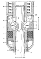
- the invention is based on a drawing that shows an embodiment explained.
- the tool holder shown in the locked position is not part of one Chisel device shown and has a receiving sleeve 1 with a central receiving bore 11 into which the insertion end of a drilling or chisel tool 2 protrudes.
- the receiving sleeve 1 has two diametrically opposite passage openings 12 provided, which extend parallel to the longitudinal axis of the receiving sleeve 1.
- the receiving sleeve 1 is surrounded by a stop ring 3 and one against the machining direction to the stop ring 3, elastic Damping ring 4 and a guide ring 5.
- the stop ring 3 is at least in Machining direction axially fixed.
- the guide ring 5 interacts with two diametrically opposite locking elements 6 together and keeps them a radially inwardly directed stop surface 51 in a locking position in which they pass through the openings 12 of the receiving sleeve 1 and in two each other diametrically opposite, axially closed longitudinal grooves 21 of the tool 2 protrude.
- Each locking element 6 is composed of one machining-side locking area 61 with the length L1 and one on it adjoining stop area 62. Since the length L1 of the locking area 61 is less than the length of the axially closed longitudinal groove 21 in the tool 2 axially limited displaceable in the locking position of the tool holder. The length L1 of the locking area 61 corresponds approximately to 0.5 times the length L2 of the Passage opening 12.
- Each locking element 6 is opposite to the machining direction adjoining actuating sleeve 7 in connection and is perpendicular to the Longitudinal axis of the receiving sleeve 1 aligned pivot axis S with respect to Actuating sleeve 7 tiltable.
Landscapes
- Engineering & Computer Science (AREA)
- Mechanical Engineering (AREA)
- Gripping On Spindles (AREA)
- Percussive Tools And Related Accessories (AREA)
Claims (6)
- Porte-outil pour outils de forage et/ou de burinage comprenant une douille de réception (1) qui sert à recevoir un outil (2) et qui est pourvu d'au moins un orifice traversant (12), une douille d'actionnement (7) qui entoure la douille de réception (1) et est déplaçable à l'opposé de la direction de travail à l'encontre de la force d'un ressort (8), au moins un élément de verrouillage (6) qui peut basculer de manière limitée autour d'un axe de basculement (S) orienté perpendiculairement à l'axe longitudinal de la douille de réception (1) et qui traverse au moins partiellement l'orifice traversant (12) et, en position verrouillée, pénètre dans le diamètre intérieur de la douille de réception (1), une bague de. guidage (5) qui entoure la douille de réception (1) et qui, dans la position verrouillée, recouvre au moins une partie de l'élément de verrouillage (6) et empêche ainsi l'élément de verrouillage (6) de basculer dans une position libérée, caractérisé en ce que l'élément de verrouillage (6) est relié à la douille d'actionnement (7) et ce, de manière basculante autour d'un axe de basculement (S) de la douille d'actionnement (7).
- Porte-outil selon la revendication 1, caractérisé en ce que l'élément de verrouillage (6) comporte une zone de verrouillage (61) pénétrant dans l'orifice traversant (12) et une zone de liaison (62) qui se raccorde à la zone de verrouillage (61) à l'opposé de la direction de travail et est reliée à la douille d'actionnement (7).
- Porte-outil selon la revendication 2, caractérisé en ce que la plus grande longueur (L1) de la zone de verrouillage (61), laquelle s'étend parallèlement à l'axe longitudinal de la douille de réception (1), est inférieure à l'extension (L2) de l'orifice traversant (12), laquelle s'étend parallèlement à l'axe longitudinal de la douille de réception (1).
- Porte-outil selon la revendication 3, caractérisé en ce que la longueur (L1) de la zone de verrouillage (61) correspond à 0,3 à 0,8 fois l'extension (L2) de l'orifice traversant (12).
- Porte-outil selon une des revendications 1 à 4, caractérisé en ce que la bague de guidage (5) prend appui, dans la direction de travail, sur un élément amortisseur élastique (4) .
- Porte-outil selon une des revendications 1 à 5, caractérisé en ce que deux éléments de verrouillage diamétralement opposés (6) sont prévus.
Applications Claiming Priority (2)
| Application Number | Priority Date | Filing Date | Title |
|---|---|---|---|
| DE19834503 | 1998-07-31 | ||
| DE19834503A DE19834503A1 (de) | 1998-07-31 | 1998-07-31 | Werkzeughalter für Bohr- und Meisselgeräte |
Publications (2)
| Publication Number | Publication Date |
|---|---|
| EP0976506A1 EP0976506A1 (fr) | 2000-02-02 |
| EP0976506B1 true EP0976506B1 (fr) | 2002-08-14 |
Family
ID=7875937
Family Applications (1)
| Application Number | Title | Priority Date | Filing Date |
|---|---|---|---|
| EP99810533A Expired - Lifetime EP0976506B1 (fr) | 1998-07-31 | 1999-06-17 | Porte-outil pour forets et ciseaux |
Country Status (5)
| Country | Link |
|---|---|
| US (1) | US6135461A (fr) |
| EP (1) | EP0976506B1 (fr) |
| JP (1) | JP4256539B2 (fr) |
| CN (1) | CN1116150C (fr) |
| DE (1) | DE19834503A1 (fr) |
Families Citing this family (24)
| Publication number | Priority date | Publication date | Assignee | Title |
|---|---|---|---|---|
| US6467987B1 (en) * | 1999-03-29 | 2002-10-22 | Honeywell International Inc. | Resettable non-explosive actuator |
| DE10026021A1 (de) * | 2000-05-25 | 2001-11-29 | Hilti Ag | Werkzeugaufnahme für einen Bohrmeissel |
| DE10043416A1 (de) * | 2000-09-04 | 2002-03-14 | Hilti Ag | Schlagendes Handwerkzeuggerät mit Werkzeugaufnahme |
| DE10044387A1 (de) * | 2000-09-08 | 2002-04-04 | Bosch Gmbh Robert | Werkzeughalterung für eine Handwerkzeugmaschine |
| GB0105547D0 (en) | 2001-03-07 | 2001-04-25 | Black & Decker Inc | Tool holder for a rotary hammer or a chisel hammer |
| GB0121947D0 (en) * | 2001-09-12 | 2001-10-31 | Black & Decker Inc | Tool holder for hammer |
| GB0121958D0 (en) * | 2001-09-12 | 2001-10-31 | Black & Decker Inc | Tool holder for hammer |
| DE10243290B4 (de) * | 2002-09-18 | 2007-04-05 | Robert Bosch Gmbh | Werkzeugaufnahme |
| GB2394202A (en) * | 2002-10-18 | 2004-04-21 | Black & Decker Inc | Tool holder for impacting machine |
| DE10324426A1 (de) * | 2003-05-30 | 2004-12-16 | Robert Bosch Gmbh | Handwerkzeugmaschine |
| DE102005000168A1 (de) * | 2005-11-25 | 2007-05-31 | Hilti Ag | Werkzeugaufnahme |
| US8690876B2 (en) | 2011-04-07 | 2014-04-08 | DePuy Synthes Products, LLC | Cutting burr shank configuration |
| US8801713B2 (en) | 2011-04-07 | 2014-08-12 | DePuy Synthes Products, LLC | Surgical drill instrument with motor and locking mechanism to receive an attachment and a cutting burr |
| DE102011075861A1 (de) * | 2011-05-16 | 2012-11-22 | Robert Bosch Gmbh | Werkzeugaufnahme |
| EP2799188A4 (fr) | 2011-12-28 | 2015-08-12 | Positec Power Tools Suzhou Co | Outil électrique |
| CN103182706B (zh) * | 2011-12-28 | 2016-02-17 | 苏州宝时得电动工具有限公司 | 动力工具 |
| US9662778B2 (en) | 2012-02-10 | 2017-05-30 | Milwaukee Electric Tool Corporation | Bit retention assembly for rotary hammer |
| WO2014075165A1 (fr) * | 2012-11-14 | 2014-05-22 | British Columbia Cancer Agency Branch | Accessoire de marteau perforateur tubulaire |
| GB201411392D0 (en) * | 2014-06-26 | 2014-08-13 | Black & Decker Inc | A tool holder |
| US9579731B2 (en) * | 2015-07-29 | 2017-02-28 | Kaarle Homola | Drill chuck assembly |
| US10206691B2 (en) * | 2015-10-29 | 2019-02-19 | Medtronic Xomed, Inc. | Method and apparatus to select vibration |
| US10058927B2 (en) * | 2016-02-04 | 2018-08-28 | Mince Master Inc. | Spindle clamp for tool holder |
| US12102369B2 (en) * | 2021-05-13 | 2024-10-01 | DePuy Synthes Products, Inc. | Surgical impacting tool interfaces |
| US12496696B2 (en) * | 2022-09-09 | 2025-12-16 | Techtronic Cordless Gp | Tool assembly and attachment apparatus for tool head |
Family Cites Families (4)
| Publication number | Priority date | Publication date | Assignee | Title |
|---|---|---|---|---|
| US2432144A (en) * | 1945-04-02 | 1947-12-09 | Irving A Elkins | Toolholder and lock |
| US4219854A (en) | 1978-12-21 | 1980-08-26 | International Business Machines Corporation | Thin film magnetic head assembly |
| DE19521993B4 (de) * | 1995-06-20 | 2009-04-09 | Robert Bosch Gmbh | Werkzeughalter und Werkzeug für eine Bohr- und/oder Schlagwerkzeugmaschine |
| DE29612795U1 (de) * | 1996-07-24 | 1997-11-20 | Robert Bosch Gmbh, 70469 Stuttgart | Werkzeughalter für elektrische Handwerkzeugmaschinen |
-
1998
- 1998-07-31 DE DE19834503A patent/DE19834503A1/de not_active Withdrawn
-
1999
- 1999-06-17 EP EP99810533A patent/EP0976506B1/fr not_active Expired - Lifetime
- 1999-07-23 CN CN99110535A patent/CN1116150C/zh not_active Expired - Lifetime
- 1999-07-26 US US09/360,743 patent/US6135461A/en not_active Expired - Lifetime
- 1999-07-27 JP JP21194499A patent/JP4256539B2/ja not_active Expired - Lifetime
Also Published As
| Publication number | Publication date |
|---|---|
| EP0976506A1 (fr) | 2000-02-02 |
| US6135461A (en) | 2000-10-24 |
| DE19834503A1 (de) | 2000-02-03 |
| JP4256539B2 (ja) | 2009-04-22 |
| JP2000052114A (ja) | 2000-02-22 |
| CN1247782A (zh) | 2000-03-22 |
| CN1116150C (zh) | 2003-07-30 |
Similar Documents
| Publication | Publication Date | Title |
|---|---|---|
| EP0976506B1 (fr) | Porte-outil pour forets et ciseaux | |
| EP0785041B1 (fr) | Mandrin porte-foret | |
| EP0765707B1 (fr) | Porte-outil pour appareil à forer et à buriner | |
| DE3205063C2 (de) | Werkzeughalter | |
| EP1326736B1 (fr) | Porte-outil pour une machine-outil | |
| DE4340726C1 (de) | Einrichtung an Handwerkzeugmaschinen zur Drehmitnahme von Werkzeugen | |
| DE3125455A1 (de) | Werkzeughalter fuer bohr- und schlagbohrgeraete | |
| EP0876881B1 (fr) | Appareil de forage et/ou percussion | |
| EP0710519A2 (fr) | Mandrin porte-foret | |
| DE2354168A1 (de) | Werkzeughalter fuer eine handwerkzeugmaschine | |
| EP1184136B1 (fr) | Outil main à percussion avec porte-outil | |
| CH619634A5 (fr) | ||
| DE19827172A1 (de) | Werkzeughalter | |
| EP0598176A1 (fr) | Mandrin de perçage | |
| DE4104131A1 (de) | Handbohrmaschine | |
| DE10241054A1 (de) | Werkzeug und Werkzeughalter für eine Handwerkzeugmaschine | |
| DE69503272T2 (de) | Werkzeughalter für einen Bohrhammer und/oder Meisselhammer | |
| AT390750B (de) | Bohrfutter fuer schlagbohrbetrieb | |
| EP0768151B1 (fr) | Porte-outil | |
| DE102005001535B3 (de) | Befestigungsanordnung für einen Meißel und Demontagewerkzeug | |
| EP1122033B1 (fr) | Manche d'outil | |
| DE19503525B4 (de) | Handwerkzeugmaschine, insbesondere Bohr- und/oder Schlaghammer | |
| DE19724532A1 (de) | Handgeführte Bohr- oder Schlagwerkzeugmaschine | |
| DE4136584B4 (de) | Bohr- und Meisselgerät mit Werkzeugaufnahme | |
| EP0943395B1 (fr) | Perçeuse munie d'un aspirateur |
Legal Events
| Date | Code | Title | Description |
|---|---|---|---|
| PUAI | Public reference made under article 153(3) epc to a published international application that has entered the european phase |
Free format text: ORIGINAL CODE: 0009012 |
|
| AK | Designated contracting states |
Kind code of ref document: A1 Designated state(s): CH FR GB LI NL SE |
|
| AX | Request for extension of the european patent |
Free format text: AL;LT;LV;MK;RO;SI |
|
| 17P | Request for examination filed |
Effective date: 20000802 |
|
| AKX | Designation fees paid |
Free format text: CH FR GB LI NL SE |
|
| GRAG | Despatch of communication of intention to grant |
Free format text: ORIGINAL CODE: EPIDOS AGRA |
|
| GRAG | Despatch of communication of intention to grant |
Free format text: ORIGINAL CODE: EPIDOS AGRA |
|
| GRAH | Despatch of communication of intention to grant a patent |
Free format text: ORIGINAL CODE: EPIDOS IGRA |
|
| 17Q | First examination report despatched |
Effective date: 20020128 |
|
| REG | Reference to a national code |
Ref country code: DE Ref legal event code: 8566 |
|
| GRAH | Despatch of communication of intention to grant a patent |
Free format text: ORIGINAL CODE: EPIDOS IGRA |
|
| GRAA | (expected) grant |
Free format text: ORIGINAL CODE: 0009210 |
|
| AK | Designated contracting states |
Kind code of ref document: B1 Designated state(s): CH FR GB LI NL SE |
|
| REG | Reference to a national code |
Ref country code: GB Ref legal event code: FG4D Free format text: NOT ENGLISH |
|
| REG | Reference to a national code |
Ref country code: CH Ref legal event code: EP |
|
| GBT | Gb: translation of ep patent filed (gb section 77(6)(a)/1977) |
Effective date: 20020919 |
|
| ET | Fr: translation filed | ||
| PLBE | No opposition filed within time limit |
Free format text: ORIGINAL CODE: 0009261 |
|
| STAA | Information on the status of an ep patent application or granted ep patent |
Free format text: STATUS: NO OPPOSITION FILED WITHIN TIME LIMIT |
|
| 26N | No opposition filed |
Effective date: 20030515 |
|
| PGFP | Annual fee paid to national office [announced via postgrant information from national office to epo] |
Ref country code: NL Payment date: 20040603 Year of fee payment: 6 |
|
| PG25 | Lapsed in a contracting state [announced via postgrant information from national office to epo] |
Ref country code: NL Free format text: LAPSE BECAUSE OF NON-PAYMENT OF DUE FEES Effective date: 20060101 |
|
| NLV4 | Nl: lapsed or anulled due to non-payment of the annual fee |
Effective date: 20060101 |
|
| REG | Reference to a national code |
Ref country code: FR Ref legal event code: PLFP Year of fee payment: 18 |
|
| REG | Reference to a national code |
Ref country code: FR Ref legal event code: PLFP Year of fee payment: 19 |
|
| REG | Reference to a national code |
Ref country code: FR Ref legal event code: PLFP Year of fee payment: 20 |
|
| PGFP | Annual fee paid to national office [announced via postgrant information from national office to epo] |
Ref country code: CH Payment date: 20180621 Year of fee payment: 20 |
|
| PGFP | Annual fee paid to national office [announced via postgrant information from national office to epo] |
Ref country code: FR Payment date: 20180620 Year of fee payment: 20 |
|
| PGFP | Annual fee paid to national office [announced via postgrant information from national office to epo] |
Ref country code: SE Payment date: 20180620 Year of fee payment: 20 |
|
| PGFP | Annual fee paid to national office [announced via postgrant information from national office to epo] |
Ref country code: GB Payment date: 20180620 Year of fee payment: 20 |
|
| REG | Reference to a national code |
Ref country code: CH Ref legal event code: PL |
|
| REG | Reference to a national code |
Ref country code: GB Ref legal event code: PE20 Expiry date: 20190616 |
|
| REG | Reference to a national code |
Ref country code: SE Ref legal event code: EUG |
|
| PG25 | Lapsed in a contracting state [announced via postgrant information from national office to epo] |
Ref country code: GB Free format text: LAPSE BECAUSE OF EXPIRATION OF PROTECTION Effective date: 20190616 |