EP0976557A1 - Dispositif d'impression utilisant des polymères hydrophiles/hydrophobes - Google Patents
Dispositif d'impression utilisant des polymères hydrophiles/hydrophobes Download PDFInfo
- Publication number
- EP0976557A1 EP0976557A1 EP99420160A EP99420160A EP0976557A1 EP 0976557 A1 EP0976557 A1 EP 0976557A1 EP 99420160 A EP99420160 A EP 99420160A EP 99420160 A EP99420160 A EP 99420160A EP 0976557 A1 EP0976557 A1 EP 0976557A1
- Authority
- EP
- European Patent Office
- Prior art keywords
- state
- polymer element
- event
- polymer
- fluid
- Prior art date
- Legal status (The legal status is an assumption and is not a legal conclusion. Google has not performed a legal analysis and makes no representation as to the accuracy of the status listed.)
- Granted
Links
Images


Classifications
-
- B—PERFORMING OPERATIONS; TRANSPORTING
- B41—PRINTING; LINING MACHINES; TYPEWRITERS; STAMPS
- B41J—TYPEWRITERS; SELECTIVE PRINTING MECHANISMS, i.e. MECHANISMS PRINTING OTHERWISE THAN FROM A FORME; CORRECTION OF TYPOGRAPHICAL ERRORS
- B41J2/00—Typewriters or selective printing mechanisms characterised by the printing or marking process for which they are designed
- B41J2/005—Typewriters or selective printing mechanisms characterised by the printing or marking process for which they are designed characterised by bringing liquid or particles selectively into contact with a printing material
Definitions
- the present invention relates to a printing device, specifically, to an ink jet printing device.
- the present invention also relates to a printing process using such a device.
- the object of almost all the printing technologies developed today is to produce high quality copies as fast as possible, at the lowest possible cost.
- the printing process in technologies relevant to thermal ink jet heads, conventionally has two steps.
- the first step consists in forming an ink drop and the second step consists in ejecting the ink drop from the ink jet head towards a receiving support.
- the formation of the ink drop requires raising the ink found in a channel to a high temperature in a very short time. This method requires heat in the volume of the ink jet head itself, which must then be dissipated.
- the drop can be ejected by different techniques, for example by the application of an electrostatic field.
- One of the ink jet technologies in order to achieve fast printing consists in the use of a plurality of nozzles on the head surface that can eject ink drops in order to print a larger number of points in parallel on the receiving support.
- the number of nozzles on the head surface is restricted either because of problems related to heat dissipation in methods that consist in carrying high temperature ink as in the technologies developed by Canon and Hewlett Packard, or because of problems related to dimensional instability due to the vibrations caused by the use of piezoelectric technologies like those developed by Seiko-Epson.
- print devices have to be developed containing micro-elements that are generally very costly.
- the present invention proposes the provision of a new printing device using polymers exhibiting specific properties.
- the present invention relates to a printing device comprising a polymer element capable of switching from an initial state to a final state when subjected to an event, the initial state and the final state being selected from an hydrophilic state and an hydrophobic state provided that the initial state differs form the second state, and a controller adapted to generate the event producing the switch on a localized zone of the polymer element.
- the present invention also relates to a method that comprises impregnating with a printing fluid a polymer element capable of switching from an initial state to a final state when subjected to an event, the initial state and the final state being selected from an hydrophilic state and an hydrophobic state provided that the initial state differs form the final state, generating an event for producing the switch of the polymer element thus forming at the polymer surface a printing fluid drop, and contacting the drop fluid with a printing receiver element.
- the present invention has the advantage of forming a heat dissipating ink jet head.
- the ink jet head is created at the moment of use and for the duration of this use.
- the printing device of the invention allows printing a low temperature, avoiding any problems relating to the heat dissipation.
- the invention device eliminates any need for complex mechanics such as those used in known ink jet heads.
- the device of the present invention has a low manufacturing cost.
- the polymer element of the invention can be a polymer element that is initially in a hydrophilic state and switches to turn into a hydrophobic state when subjected to an event producing the switch.
- the polymer element of the invention can also be a polymer element that is initially in a hydrophobic state and switches to turn into a hydrophilic state when subjected to the event producing the switch. These polymer elements are also able to switch from the final state to the initial stage when the event is released.
- Polymer elements that can switch from an initial state to a final state when subjected to an event are well known in the art as switchable polymer.
- the event can be any event adapted to produce the switch of the polymer element from an initial state to a final state.
- the event that can be used is determined by the nature and the initial state of the polymer element.
- the event can be for example an optical event, a thermal event, electrical event or a chemical event.
- the polymer element of the invention is a thermo-reversible polymer.
- These elements are polymer elements capable of switching from an initial state to a final state when subjected to a thermal event such as heating or cooling, depending on the nature and the initial state of the polymer element. Conventionally, these polymers exhibit a phase transition temperature Tg.
- the polymer element useful in the device of the invention is a polymer element initially in the hydrophilic state switching from a hydrophilic state to a hydrophilic state when the element is heated above its Tg, and which reverse back to the hydrophobic state when the heating is released and the polymer element returns at a temperature below Tg.
- the polymer can return to the hydrophilic state by simple heat dissipation.
- the polymer element of the invention is a thermo-reversible polymer that is hydrophilic at ambient temperature, and has a phase transition temperature between 20 and 100°C, preferably between 30 and 70°C.
- Thermo-reversible polymers that can be used in the present device are organic polymers such as those described in PCT Patent Application WO 91/15526. These are polymers that have a hydrophilic group and a hydrophobic group, the hydrophilic group being a water-soluble ionic polymerizable vinyl monomer, and the hydrophobic group comprising an acrylamide or methacrylamide monomer.
- polysilylamine a polymer that switches from the initial state to a final state fast, for example poly(N-isopropylacrylamide).
- Poly(N-isopropylacrylamide) has a temperature Tg of about 32°. When this polymer is at a temperature less than 32°, it is hydrophilic. When it exceeds 32°, it becomes hydrophobic.
- the hydrophilic/hydrophobic phase transition temperature of a polymer can be modified by different means.
- adding a surfactant to the print fluid is known to increase the phase transition temperature. This technique is described in the publication, Langmuir, 1995, Volume 11, No. 7, pages 2493-2495.
- the phase transition temperature Tg of poly(N-isopropylacrylamide) can be modified from 32°C to 90°C.
- hydrophilic/hydrophobic change of state of some polymers causes the polymer's volume to vary. According to the applications, it can be an advantage to be free of volume variations. Therefore, known techniques such as those described in Polymer Communications, "Synthesis of fast response, temperature-sensitive poly(N-isopropylacrylamide) gel", can be used.
- the polymer element of the present device can be self-supporting. It can also be supported by a support.
- the support has to transmit the event producing the switch. For example, when the event producing the switch is heating, the support need to be able to transfer the heat to the polymer element.
- the controller of the invention can be any controller adapted to generate an event producing the switch of the polymer element from an initial state to a final state.
- the controller can be adapted to generate an optical event, a thermal event, electrical event or a chemical event, depending on the nature of the polymer element.
- the controller is adapted to generate the event producing the switch of the polymer element on a localized zone delimiting an internal zone, and then on the internal zone.
- the localized zone can be a continuous zone or a discontinuous zone.
- Examples of the controller producing the switch can be heating/cooling means, a laser, electrical means, chemical means such as means to alter the pH, means to alter the ionic force, or even mechanical means such as means to alter the pressure.
- the controller is adapted to generate a thermal event.
- Heating means is for example an element comprising a thin layer of polycrystal silicon in which a current is made to flow adapted to generate a quantity of heat allowing the polymer to exceed its phase transition temperature for switching from a initial state to a final state.
- the controller is a laser beam and the polymer element is a thermo-reversible polymer element absorbing the laser's wavelength, typically 670 nm.
- One or more controller adapted to generate the event producing the switch of the polymer element on the localized zone A and then the internal zone B can be used.
- the controller is a laser beam
- two independent laser beams can be used to switch the localized zone and then the internal zone B from the initial to the final second state.
- a single laser beam can also be used, whose beam is modulated to give minimum energy to the center of the beam and maximum to the sides.
- the device of the invention can further contain an additional controller adapted to generate an appropriate event.
- This additional controller can be any controller adapted to generate the event producing the switch of the polymer element from the final state to the initial state.
- the additional controller can be adapted to generate an optical event, a thermal event, electrical event or a chemical event, depending on the nature of the polymer element.
- the additional controller will be means for cooling the polymer element, for example a fan or a pelletier effect device.
- the device of the invention can also include means for feeding a fluid into the polymer element in order to maintain a constant impregnation of the polymer element with the fluid.
- a fluid into the polymer element in order to maintain a constant impregnation of the polymer element with the fluid.
- This can be carried out by any known technique, for example with a fluid reservoir connected to the polymer, or for example by capillary diffusion.
- the fluid can be any known printing fluid containing organic or mineral pigments.
- the device of the invention can further include means for positioning a fluid receiving material.
- the fluid receiving material that can be any material known in the printing domain, for example paper, whether coated or not, in sheet or roll form.
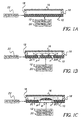
- Figure 1A shows a representation of the device of the invention which comprises a polymer element 10 impregnated with a fluid, a fluid receiving material 16, the fluid receiving material 16 being positioned in the device by means of positioning means 18, a controller 12, an additional controller 20 and means such as a reservoir 22 for feeding a fluid in the polymer element 10.
- Figure 1B when a localized zone A of the polymer element in an initial state is subjected to a suitable event by means of the controller 12, the zone A of the polymer element switches from the initial state to the final state.
- the fluid initially present in the zone A tends to be pushed out of the zone A to a zone of the polymer element 10 still in the initial state, as shown by the arrows in Figure 1B.
- the fluid is pushed into an internal zone B delimited by the zone A. It is thus obtained a localized zone A in the final state and a internal zone B in the initial state, impregnated with fluid.
- zone B switches from the initial state to the final state, thereby moving the fluid contained in zone B outside the zone B toward the polymer surface opposed to the surface subjected to the event to form a fluid drop 14 at the surface of the polymer element.
- a print is then obtained by contacting the fluid drop 14 at the surface of the zone B of the polymer element with the fluid receiving material 16.
- the fluid drop 14 can also be ejected from the surface to the fluid receiving material.
- the drop can be ejected for example by the application of an electric field, or by any known techniques.
- the zone A can be continuous or discontinuous.
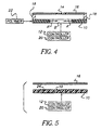
- Figure 2A shows an example of a polymer element after subjecting a localized continuous zone A to the event.
- Figure 2B shows the same polymer element after subjecting the internal zone B to the event.
- Figure 3A shows an example of a polymer element after subjecting a localized discontinuous zone A to the event.
- zone A is discontinuous
- the fluid contained in the internal zone B can spread outside this zone, as shown by the arrows in Figure 3A.
- the fluid present in the internal zone B is not completely isolated from the part of the polymer element in the initial state. Thus it can spread into the rest of the polymer still in the initial state.
- it can be desirable to delay the application of the event to zone B until a desired quantity of fluid is released from the zone B to zone A.
- Figure 3B shows the same polymer element after subjecting the internal zone B to the event, when the zone A is a discontinuous localized zone.
- the event is released from the localized zone A and the internal zone B now in the final state, for example by deactivating the controller 12.
- the localized zone A and the internal zone B of the polymer element are then able to switch from the final state to the initial state.
- the polymer is thus able to be impregnated again with the fluid through the reservoir 22 for feeding the fluid to the polymer element 10.
- the switch from the final state to the initial state of the localized zone A and the internal zone B can also be expedited by subjecting the localized zone A and the internal zone B of the polymer element to a suitable event generated by the additional controller 20.
- the device of the present invention can comprise a plurality of polymer elements as described above used successively.
- the device can comprise means to move the plurality of polymer elements.
- the device of the invention can also comprise a continuous polymer element sheet, drawn by rollers.
- the polymer elements can be associated to form a cylinder. Rotating the cylinder allows the position of the various polymer elements to be simply changed in relation to the controller 12. The speed of rotation of the cylinder will be selected according to the suitable print speed and the time the polymer element switches from the final state to the initial state, when subjected to the suitable event..
- the device of the invention can also comprise polymer elements 10 each separated from the others by a fluid insulating material 24. In that case, the entire unit is subjected to the event, the fluid insulating material 24 avoiding the spread of the fluid.
- the fluid useful in the device of the invention is a print fluid, for example a hydrophilic or hydrophobic printing ink, containing pigments or organic dyes.
- the fluid will be selected to be able to impregnate the polymer element.
- the fluid will be a hydrophilic printing fluid on order to be fed to the polymer element.
- the fluid still hydrophilic tends to spread out of the hydrophobic zone, thereby forming the fluid drop on the surface of the hydrophobic zone of the polymer element.
- the printing fluid will be an hydrophobic printing fluid.
Landscapes
- Ink Jet (AREA)
- Particle Formation And Scattering Control In Inkjet Printers (AREA)
- Micromachines (AREA)
Applications Claiming Priority (2)
| Application Number | Priority Date | Filing Date | Title |
|---|---|---|---|
| FR9809810 | 1998-07-28 | ||
| FR9809810A FR2781721B1 (fr) | 1998-07-28 | 1998-07-28 | Dispositif d'impression a partir de polymere hydrophile/hydrophobe |
Publications (2)
| Publication Number | Publication Date |
|---|---|
| EP0976557A1 true EP0976557A1 (fr) | 2000-02-02 |
| EP0976557B1 EP0976557B1 (fr) | 2005-11-09 |
Family
ID=9529235
Family Applications (1)
| Application Number | Title | Priority Date | Filing Date |
|---|---|---|---|
| EP99420160A Expired - Lifetime EP0976557B1 (fr) | 1998-07-28 | 1999-07-12 | Dispositif d'impression utilisant des polymères hydrophiles/hydrophobes |
Country Status (4)
| Country | Link |
|---|---|
| US (1) | US6394584B1 (fr) |
| EP (1) | EP0976557B1 (fr) |
| DE (1) | DE69928180D1 (fr) |
| FR (1) | FR2781721B1 (fr) |
Cited By (2)
| Publication number | Priority date | Publication date | Assignee | Title |
|---|---|---|---|---|
| WO2002022267A3 (fr) * | 2000-09-18 | 2002-08-01 | Micronics Inc | Enduits de surface, pouvant etre modifies par un moyen exterieur, pour dispositifs microfluidiques |
| EP1621344A1 (fr) * | 2004-07-27 | 2006-02-01 | Brother Kogyo Kabushiki Kaisha | Dispositif de transfert de liquides et tête de transfert de liquides |
Families Citing this family (1)
| Publication number | Priority date | Publication date | Assignee | Title |
|---|---|---|---|---|
| US20100251914A1 (en) * | 2009-04-01 | 2010-10-07 | Xerox Corporation | Imaging member |
Citations (9)
| Publication number | Priority date | Publication date | Assignee | Title |
|---|---|---|---|---|
| US4117497A (en) * | 1976-10-21 | 1978-09-26 | International Business Machines Corporation | Printing and displaying technology using selective laser beam pricking of liquid film for writing information |
| JPS60110709A (ja) * | 1983-11-21 | 1985-06-17 | Agency Of Ind Science & Technol | 側鎖にν−シクロプロピルアクリルアミド基をもつ親水性−疎水性熱可逆型材料及びその製造法 |
| JPS61219654A (ja) * | 1985-03-26 | 1986-09-30 | Toshiba Corp | インクジエツト記録装置 |
| JPS61219661A (ja) * | 1985-03-26 | 1986-09-30 | Toshiba Corp | リキツドジエツト記録装置 |
| JPS61219656A (ja) * | 1985-03-26 | 1986-09-30 | Toshiba Corp | リキツドジエツト記録装置 |
| WO1991015526A2 (fr) | 1990-04-02 | 1991-10-17 | Eastman Kodak Company | Polyacrylamides thermoreversibles thermoepaississants |
| JPH0421844A (ja) * | 1990-05-16 | 1992-01-24 | Matsushita Electric Ind Co Ltd | 画像形成装置 |
| US5278126A (en) * | 1989-03-31 | 1994-01-11 | Ricoh Company, Ltd. | Recording process and apparatus and recording medium in the same |
| JPH08230232A (ja) * | 1995-03-02 | 1996-09-10 | Matsushita Electric Ind Co Ltd | 画像形成方法 |
Family Cites Families (1)
| Publication number | Priority date | Publication date | Assignee | Title |
|---|---|---|---|---|
| US5992820A (en) * | 1997-11-19 | 1999-11-30 | Sarnoff Corporation | Flow control in microfluidics devices by controlled bubble formation |
-
1998
- 1998-07-28 FR FR9809810A patent/FR2781721B1/fr not_active Expired - Fee Related
-
1999
- 1999-07-12 DE DE69928180T patent/DE69928180D1/de not_active Expired - Lifetime
- 1999-07-12 EP EP99420160A patent/EP0976557B1/fr not_active Expired - Lifetime
- 1999-07-27 US US09/361,942 patent/US6394584B1/en not_active Expired - Fee Related
Patent Citations (9)
| Publication number | Priority date | Publication date | Assignee | Title |
|---|---|---|---|---|
| US4117497A (en) * | 1976-10-21 | 1978-09-26 | International Business Machines Corporation | Printing and displaying technology using selective laser beam pricking of liquid film for writing information |
| JPS60110709A (ja) * | 1983-11-21 | 1985-06-17 | Agency Of Ind Science & Technol | 側鎖にν−シクロプロピルアクリルアミド基をもつ親水性−疎水性熱可逆型材料及びその製造法 |
| JPS61219654A (ja) * | 1985-03-26 | 1986-09-30 | Toshiba Corp | インクジエツト記録装置 |
| JPS61219661A (ja) * | 1985-03-26 | 1986-09-30 | Toshiba Corp | リキツドジエツト記録装置 |
| JPS61219656A (ja) * | 1985-03-26 | 1986-09-30 | Toshiba Corp | リキツドジエツト記録装置 |
| US5278126A (en) * | 1989-03-31 | 1994-01-11 | Ricoh Company, Ltd. | Recording process and apparatus and recording medium in the same |
| WO1991015526A2 (fr) | 1990-04-02 | 1991-10-17 | Eastman Kodak Company | Polyacrylamides thermoreversibles thermoepaississants |
| JPH0421844A (ja) * | 1990-05-16 | 1992-01-24 | Matsushita Electric Ind Co Ltd | 画像形成装置 |
| JPH08230232A (ja) * | 1995-03-02 | 1996-09-10 | Matsushita Electric Ind Co Ltd | 画像形成方法 |
Non-Patent Citations (4)
| Title |
|---|
| PATENT ABSTRACTS OF JAPAN vol. 009, no. 260 (C - 309) 17 October 1985 (1985-10-17) * |
| PATENT ABSTRACTS OF JAPAN vol. 011, no. 064 (M - 565) 26 February 1987 (1987-02-26) * |
| PATENT ABSTRACTS OF JAPAN vol. 016, no. 182 (P - 1346) 30 April 1992 (1992-04-30) * |
| PATENT ABSTRACTS OF JAPAN vol. 097, no. 001 31 January 1997 (1997-01-31) * |
Cited By (3)
| Publication number | Priority date | Publication date | Assignee | Title |
|---|---|---|---|---|
| WO2002022267A3 (fr) * | 2000-09-18 | 2002-08-01 | Micronics Inc | Enduits de surface, pouvant etre modifies par un moyen exterieur, pour dispositifs microfluidiques |
| EP1621344A1 (fr) * | 2004-07-27 | 2006-02-01 | Brother Kogyo Kabushiki Kaisha | Dispositif de transfert de liquides et tête de transfert de liquides |
| US7527358B2 (en) | 2004-07-27 | 2009-05-05 | Brother Kogyo Kabushiki Kaisha | Liquid transfer device and liquid transfer head |
Also Published As
| Publication number | Publication date |
|---|---|
| FR2781721A1 (fr) | 2000-02-04 |
| DE69928180D1 (de) | 2005-12-15 |
| FR2781721B1 (fr) | 2000-09-29 |
| EP0976557B1 (fr) | 2005-11-09 |
| US6394584B1 (en) | 2002-05-28 |
Similar Documents
| Publication | Publication Date | Title |
|---|---|---|
| KR920010635B1 (ko) | 열용융 잉크젯트 인쇄시스템 | |
| JP3384597B2 (ja) | インク転移印刷装置及び方法 | |
| US5896155A (en) | Ink transfer printing apparatus with drop volume adjustment | |
| US5406314A (en) | Electrothermal printing ink with monodispersed synthetic pigment particles and method and apparatus for electronic printing therewith | |
| EP0600393B1 (fr) | Système de refroidissement d'une cassette d'impression dans une imprimante à jet d'encre | |
| JP4792028B2 (ja) | ナノスケール製造技術における流体の分配およびドロップ・オン・デマンド分配技術 | |
| EP2042317B1 (fr) | Procédé et appareil de formation d'image | |
| US4710780A (en) | Recorder with simultaneous application of thermal and electric energies | |
| KR100504973B1 (ko) | 방울크기변경을위한잉크젯프린트헤드 | |
| JP2001058413A (ja) | インキジェットプリントヘッド及びその製造方法 | |
| US6394584B1 (en) | Print device using hydrophilic/hydrophobic polymers | |
| EP0911161A2 (fr) | Imprimante à jet d'encre continu avec déflection des gouttes par un organe de commande micromécanique | |
| US5581290A (en) | Heating and cooling roller for electrostratic printing | |
| JP2021512809A (ja) | レーザー印刷プロセス | |
| JP2638390B2 (ja) | 感熱製版装置 | |
| KR20010100952A (ko) | 비-용융제거 습식 인쇄 멤버로의 평판인쇄 화상형성 방법 | |
| US5963230A (en) | Inkjet printer and inkjet printing method | |
| JPH0520273B2 (fr) | ||
| US5335001A (en) | Process and apparatus for forming dot image capable of controlling dot size | |
| GB2369087A (en) | Method of forming a circuit element on a surface using droplet deposition of an organically-modified polymeric-based or inorganic-based fluid | |
| EP0200488A2 (fr) | Matériel pour l'enregistrement pour appareil d'enregistrement tel que machines pour impression | |
| EP0940255B1 (fr) | Dispositif de déplacement d'un fluide | |
| JP2927266B2 (ja) | 液滴噴射装置 | |
| TW200813504A (en) | Electromagnetic waveguide | |
| JPS60115457A (ja) | インクジェット印写装置 |
Legal Events
| Date | Code | Title | Description |
|---|---|---|---|
| PUAI | Public reference made under article 153(3) epc to a published international application that has entered the european phase |
Free format text: ORIGINAL CODE: 0009012 |
|
| AK | Designated contracting states |
Kind code of ref document: A1 Designated state(s): DE FR GB |
|
| AX | Request for extension of the european patent |
Free format text: AL;LT;LV;MK;RO;SI |
|
| 17P | Request for examination filed |
Effective date: 20000708 |
|
| AKX | Designation fees paid |
Free format text: DE FR GB |
|
| 17Q | First examination report despatched |
Effective date: 20040428 |
|
| GRAP | Despatch of communication of intention to grant a patent |
Free format text: ORIGINAL CODE: EPIDOSNIGR1 |
|
| GRAS | Grant fee paid |
Free format text: ORIGINAL CODE: EPIDOSNIGR3 |
|
| GRAA | (expected) grant |
Free format text: ORIGINAL CODE: 0009210 |
|
| AK | Designated contracting states |
Kind code of ref document: B1 Designated state(s): DE FR GB |
|
| REG | Reference to a national code |
Ref country code: GB Ref legal event code: FG4D |
|
| REF | Corresponds to: |
Ref document number: 69928180 Country of ref document: DE Date of ref document: 20051215 Kind code of ref document: P |
|
| PG25 | Lapsed in a contracting state [announced via postgrant information from national office to epo] |
Ref country code: DE Free format text: LAPSE BECAUSE OF FAILURE TO SUBMIT A TRANSLATION OF THE DESCRIPTION OR TO PAY THE FEE WITHIN THE PRESCRIBED TIME-LIMIT Effective date: 20060210 |
|
| PG25 | Lapsed in a contracting state [announced via postgrant information from national office to epo] |
Ref country code: GB Free format text: LAPSE BECAUSE OF NON-PAYMENT OF DUE FEES Effective date: 20060712 |
|
| PLBE | No opposition filed within time limit |
Free format text: ORIGINAL CODE: 0009261 |
|
| STAA | Information on the status of an ep patent application or granted ep patent |
Free format text: STATUS: NO OPPOSITION FILED WITHIN TIME LIMIT |
|
| 26N | No opposition filed |
Effective date: 20060810 |
|
| PG25 | Lapsed in a contracting state [announced via postgrant information from national office to epo] |
Ref country code: FR Free format text: LAPSE BECAUSE OF FAILURE TO SUBMIT A TRANSLATION OF THE DESCRIPTION OR TO PAY THE FEE WITHIN THE PRESCRIBED TIME-LIMIT Effective date: 20061020 |
|
| EN | Fr: translation not filed | ||
| GBPC | Gb: european patent ceased through non-payment of renewal fee |
Effective date: 20060712 |
|
| PG25 | Lapsed in a contracting state [announced via postgrant information from national office to epo] |
Ref country code: FR Free format text: LAPSE BECAUSE OF FAILURE TO SUBMIT A TRANSLATION OF THE DESCRIPTION OR TO PAY THE FEE WITHIN THE PRESCRIBED TIME-LIMIT Effective date: 20051109 |